After I posted my Raspberry Pi server room rack temperature monitor project, I received many questions on how to integrate LCD displays with the Pi. This video is the first in a series of tutorials:
Here is the wiring that I used to connect the 16×2 display in 4 bit mode to the Pi. Please note that you can use any 6 GPIO pins.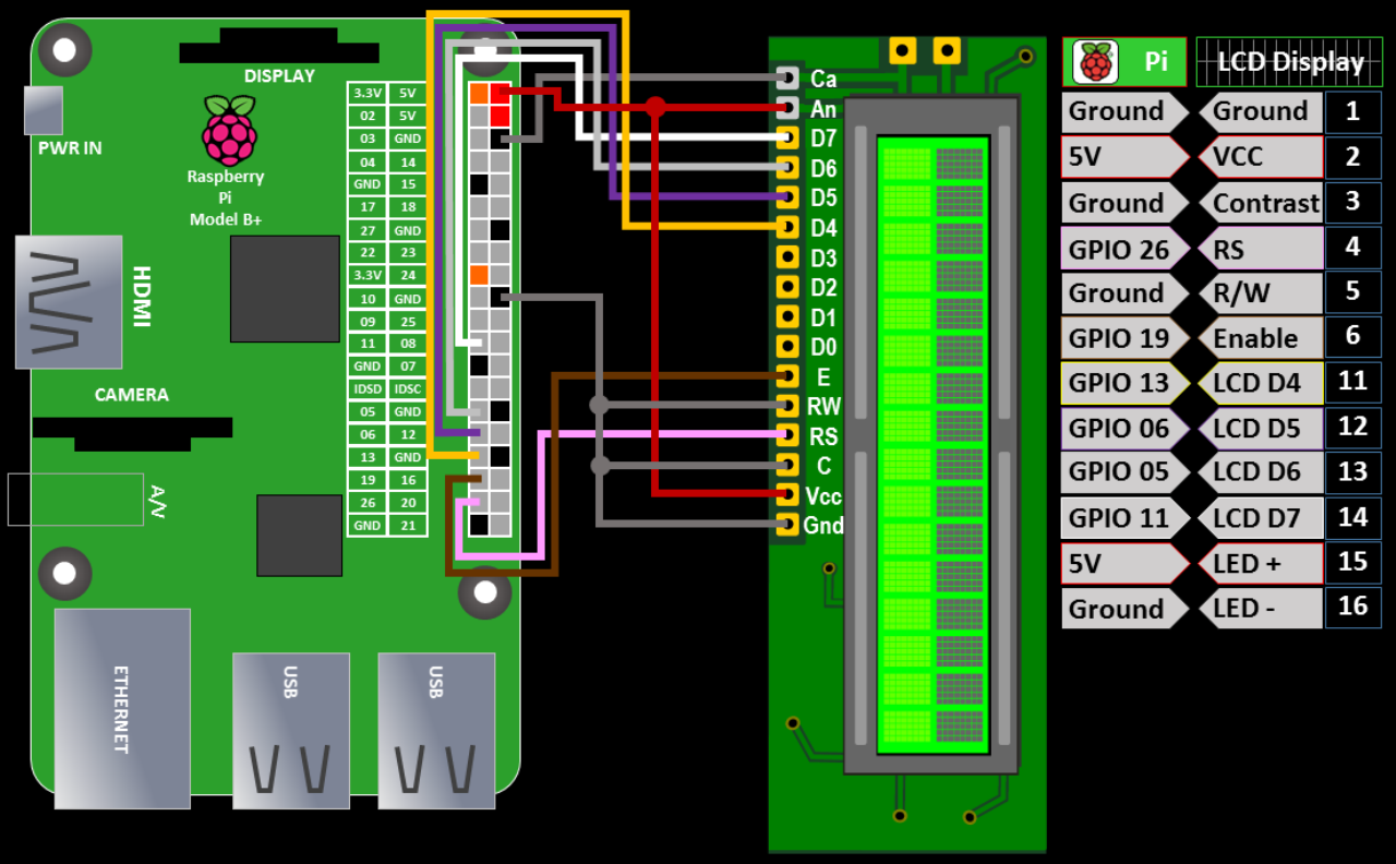
The pin outs of LCD displays can vary as well as the power requirements for the back light so please check your datasheets.
Some LED back lights can be damaged by running them at 5 V without a resistor.
Here is the formula to determine the proper resistor: R = (Vdd – VLED) / ILED
R is the resistor value in ohms and Vdd is the supply voltage. VLED and ILED are the typical LED voltage and current respectively as specified in the LCD display datasheet. Even if you display supports 5 V you might want to add a resistor or variable resistor to control the brightness. The same holds true for the contrast pin. I normally use variable resistors for both (see below).
I’ll demonstrate 2 different Python modules for controlling the LCD display. The first is a modified version of lcd.py by Raspberry Pi Spy which can be downloaded below.
 UPDATE: super-user privileges are no longer required for GPIO access with the latest version of Raspbian. Therefore, GKSU is unnecessary. Also Thonny is now the default Python editor instead of Idle.
Here is code to test the module:
import sys
# make sure module is in the path
sys.path.append('/home/pi/lcd')
import lcd
lcd.lcd_init()
# set cursor to line 1
lcd.lcd_byte(lcd.LCD_LINE_1, lcd.LCD_CMD)
# display text centered on line 1
lcd.lcd_string("Raspberry Pi", 2)
# set cursor to line 2
lcd.lcd_byte(lcd.LCD_LINE_2, lcd.LCD_CMD)
# display additional text on line 2
lcd.lcd_string("Model B+", 2)
lcd.GPIO.cleanup()
You can use any GPIO pins for the LCD RS, E, & D1 – D4. The GPIO to LCD pin mappings are specified in the LCD.py file. If you change from the default below then you have to update the file with your new selections.
# Define GPIO to LCD mapping
LCD_RS = 26
LCD_E  = 19
LCD_D4 = 13
LCD_D5 = 6
LCD_D6 = 5
LCD_D7 = 11
The 2nd Python LCD library is Char_LCD by Adafruit.
 UPDATE: the Adafruit Python CharLCD library is now deprecated. Adafruit now only supports CircuitPython for use with Python. Please see example below.
 UPDATE: the Adafruit library is now installed using pip. It is no longer necessary to use git and the paths are automatically set up.
sudo pip install adafruit-charlcd
The Adafruit library has several additional methods. Please note that their syntax has changed since the video.
# turn display on or off (Set enable to True for On, False for Off)
enable_display(enable)

# turn cursor underline on or off (Set show to True to display cursor)
show_cursor(show)

# turn blinking cursor on or off (Set blink to True to display blinking cursor)
blink(blink)

# scroll text left or right one position
move_left()	move_right()

# move cursor to top row and first column
home()

# move cursor (zero based, ex: 7,1 would be column 8, row 2)
set_cursor(col, row)
Here is some sample code (updated 4/23/16) to demonstrate the Adafruit library. As with the LCD.py module, you can use any GPIO pins. You specify the GPIO to LCD pin mappings when you instantiate the Adafruit_CharLCD class. Please note that super-user privileges are no longer required for GPIO access with the latest version of Raspbian
from time import sleep
from Adafruit_CharLCD import Adafruit_CharLCD

# instantiate lcd and specify pins
lcd = Adafruit_CharLCD(rs=26, en=19,
                       d4=13, d5=6, d6=5, d7=11,
                       cols=16, lines=2)
lcd.clear()
# display text on LCD display \n = new line
lcd.message('Adafruit CharLCD\n  Raspberry Pi')
sleep(3)
# scroll text off display
for x in range(0, 16):
    lcd.move_right()
    sleep(.1)
sleep(3)
# scroll text on display
for x in range(0, 16):
    lcd.move_left()
    sleep(.1)
Contast & Brightness:
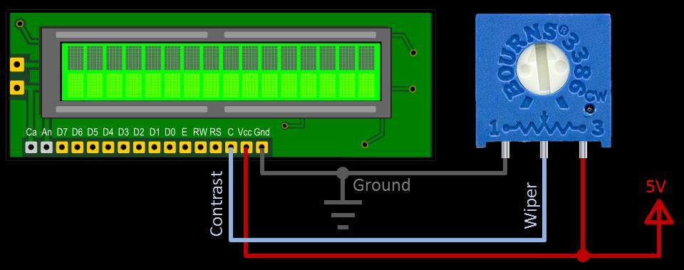
A potentiometer can be added to the LCD display C pin to control the contrast. The pin is connected to the wiper of the pot which is usually the middle pin. One of the outside pins is connected to ground and the other to Vcc. It doesn’t matter which outside pin goes to Vcc or ground because the pot is acting as a voltage divider either way. As the dial is turned the wiper’s pin voltage will vary from 0 to 5 V and this will cause the contrast to change. 10 KΩ is a good value for the pot. This same wiring will also work to control the LCD display brightness. Instead of of the contrast pin, the wiper would be connected to the LED back light anode. Most LCD display back lights will tolerate 5 V but please double check so you don’t damage the LED. You can alter the 0 – 5 V range by adding a resistor in series with one of the outside pins. This can help fine tune the amount of range provided by the pot. You can use a multimeter to measure the voltage on the wiper and determine how different resistors affect the range. Here is a simple schematic:
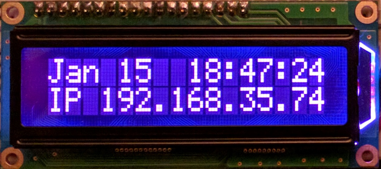
IP Clock Example:
The Adafruit IP clock example from the video is no longer compatible with the latest version of the Adafruit LCD_Char library. Here is an updated version of the IP clock program. Please note that sudo is no longer necessary to run the program with the latest version of Raspbian, but you still need the shebang line and chmod +x to give the file executable permissions, if you run it from the command line.
#!/usr/bin/python
from Adafruit_CharLCD import Adafruit_CharLCD
from time import sleep, strftime
from datetime import datetime
import socket

#  Initialize LCD (must specify pinout and dimensions)
lcd = Adafruit_CharLCD(rs=26, en=19,
                       d4=13, d5=6, d6=5, d7=11,
                       cols=16, lines=2)

def get_ip_address():
    return [
             (s.connect(('8.8.8.8', 53)),
              s.getsockname()[0],
              s.close()) for s in
                  [socket.socket(socket.AF_INET, socket.SOCK_DGRAM)]
           ][0][1]

try:
    while 1:
        lcd.clear()
        ip = get_ip_address()
        lcd.message(datetime.now().strftime('%b %d  %H:%M:%S\n'))
        lcd.message('IP {}'.format(ip))
        sleep(2)

except KeyboardInterrupt:
    print('CTRL-C pressed.  Program exiting...')

finally:
    lcd.clear()
CircuitPython Example:
The Adafruit_Python_CharLCD library has been deprecated since this tutorial was released in 2014. Therefore, I’m including an example using the newer Adafruit_CircuitPython_CharLCD library which can run on both the Raspberry Pi and other CircuitPython compatible boards. I have several CircuitPython tutorials. The library can easily be installed using pip:
sudo pip install adafruit-circuitpython-charlcd
Here’s a sample program using the newer library:
from time import sleep
import board
from digitalio import DigitalInOut
from adafruit_character_lcd.character_lcd import Character_LCD_Mono

# Modify this if you have a different sized character LCD
lcd_columns = 16
lcd_rows = 2

lcd_rs = DigitalInOut(board.D26)
lcd_en = DigitalInOut(board.D19)
lcd_d4 = DigitalInOut(board.D13)
lcd_d5 = DigitalInOut(board.D6)
lcd_d6 = DigitalInOut(board.D5)
lcd_d7 = DigitalInOut(board.D11)

# Initialise the LCD class
lcd = Character_LCD_Mono(
    lcd_rs, lcd_en, lcd_d4, lcd_d5, lcd_d6, lcd_d7, lcd_columns, lcd_rows
)
# display text on LCD display \n = new line
lcd.message = "Adafruit CharLCD\nCP Raspberry Pi"
sleep(3)

# scroll text off display
for x in range(0, 16):
    lcd.move_right()
    sleep(.2)
sleep(2)
# scroll text on display
for x in range(0, 16):
    lcd.move_left()
    sleep(.2)
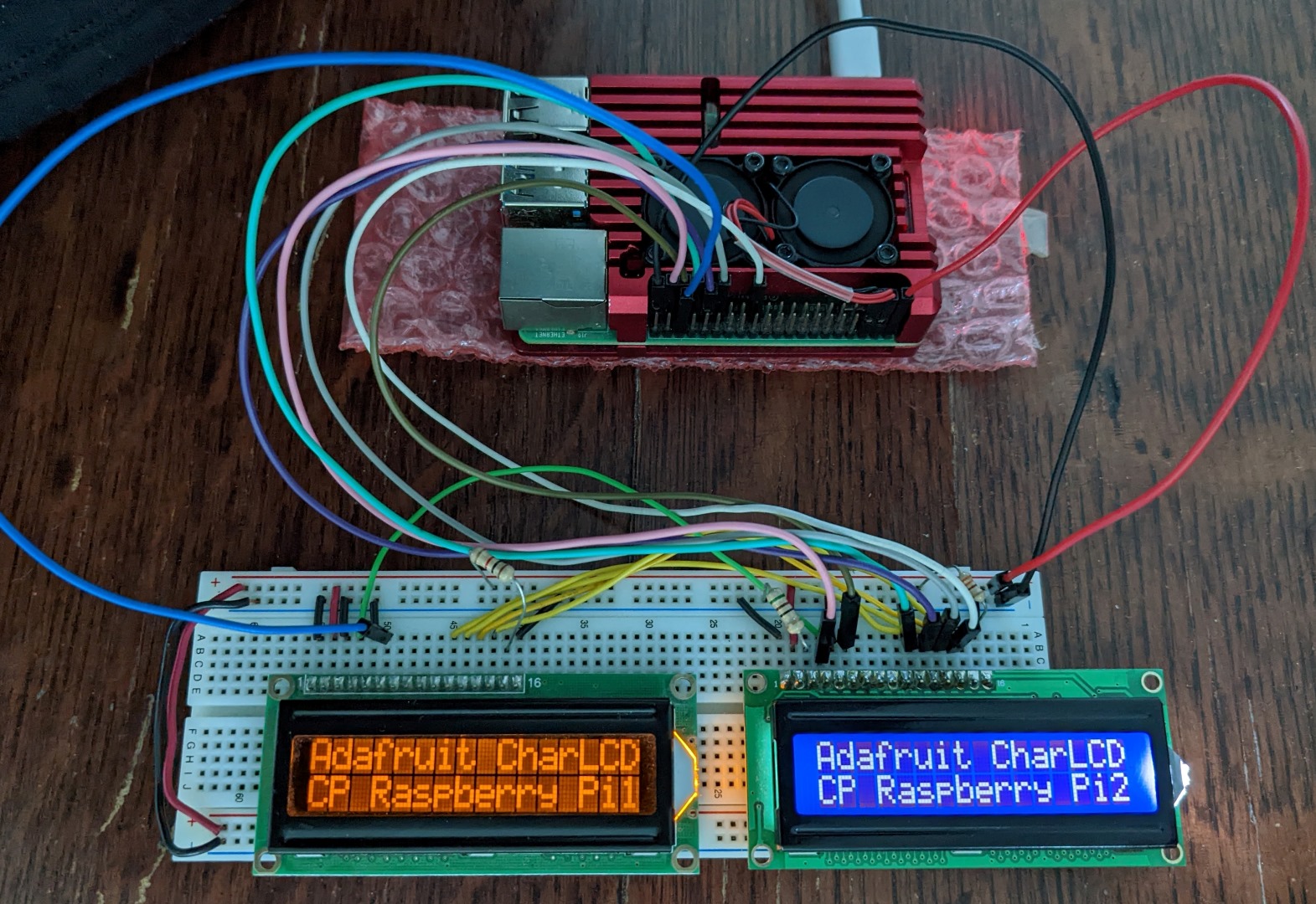
Daisy Chain LCD Displays:
It is possible to connect multiple LCD displays to a Raspberry Pi. Normally I’d recommend using an I²C display as discussed in my Using an I²C LCD Display with a Raspberry Pi tutorial because the wiring is less complicated. However, LCD displays can be daisy chained in 4 bit mode. The second display is connected to the existing GPIO pins for RS and D1 – D4, but each display must have a unique GPIO pin for Enable.
from time import sleep
import board
from digitalio import DigitalInOut
from adafruit_character_lcd.character_lcd import Character_LCD_Mono

# Modify this if you have a different sized character LCD
lcd_columns = 16
lcd_rows = 2

lcd_rs = DigitalInOut(board.D26)
lcd_en = DigitalInOut(board.D19)
lcd_en2 = DigitalInOut(board.D16)
lcd_d4 = DigitalInOut(board.D13)
lcd_d5 = DigitalInOut(board.D6)
lcd_d6 = DigitalInOut(board.D5)
lcd_d7 = DigitalInOut(board.D11)

# Initialise the LCD class
lcd = Character_LCD_Mono(
    lcd_rs, lcd_en, lcd_d4, lcd_d5, lcd_d6, lcd_d7, lcd_columns, lcd_rows
)
lcd2 = Character_LCD_Mono(
    lcd_rs, lcd_en2, lcd_d4, lcd_d5, lcd_d6, lcd_d7, lcd_columns, lcd_rows
)
lcd.clear()
lcd2.clear()

# display text on LCD display \n = new line
lcd.message = "Adafruit CharLCD\nCP Raspberry Pi1"
lcd2.message = "Adafruit CharLCD\nCP Raspberry Pi2"