
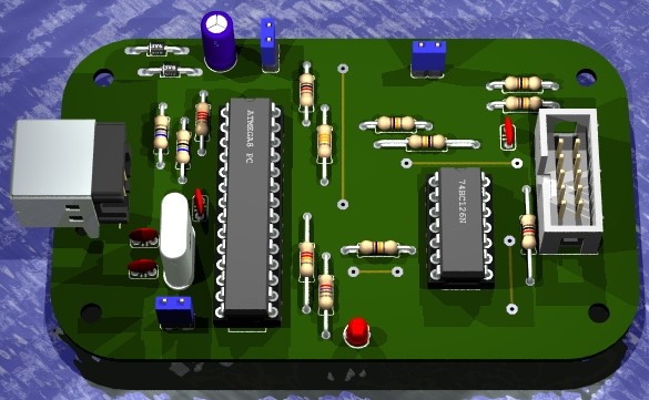
Below is a 3D model of the streamlined AVR Doper created in POV-Ray using Eagle3D. I only wanted to build an ISP so I was able to lose many of the components related to HVSP. I rounded the edges and scaled the board to fit in an Altoids tin.
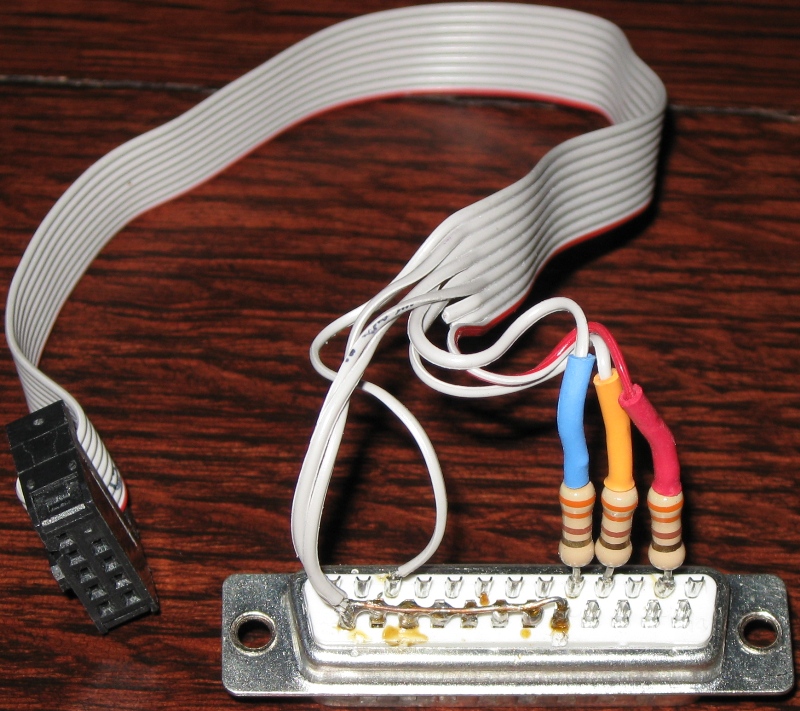
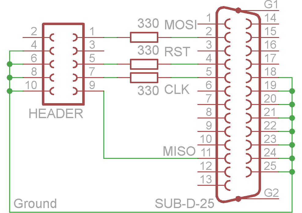
My simple inexpensive parallel ISP programmer below has done the job since I started working with AVR’s, but it definitely has its problems. It doesn’t work with some computers, it is slow, it is unreliable and it requires a parallel port which is getting less common.
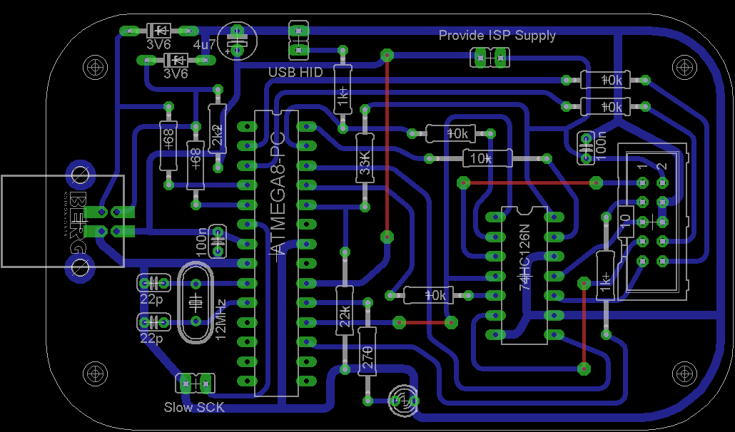
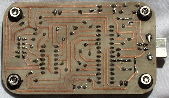
USB seemed the natural progression so I selected the AVR Doper project by Objective Development as the base for the new programmer. I modified the Objective Development schematics and circuit board using the free version of CadSoft Eagle. I designed the board to be single-sided but it does require 4 bridges.
I etched the circuit board using a laser printer, glossy photo paper, hydrogen peroxide and muriatic acid. Here are my etching notes.
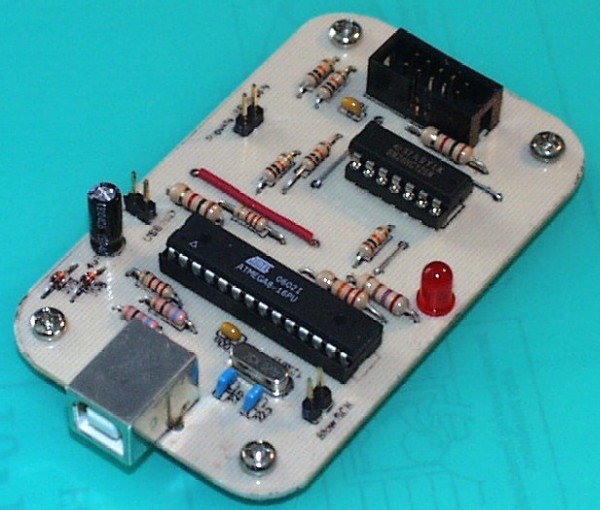
Here is the completed board.
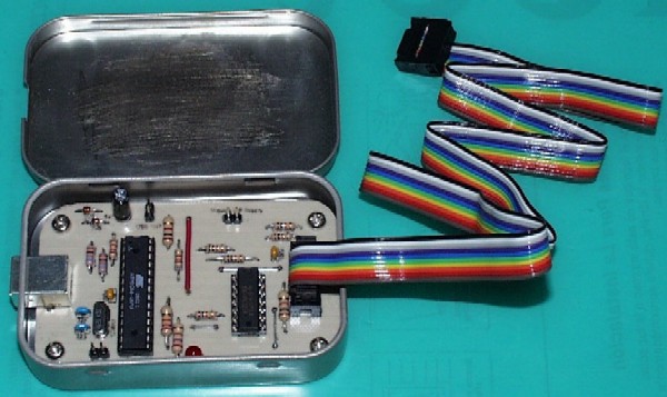
Here is a shot of the board mounted in the Altoids tin.
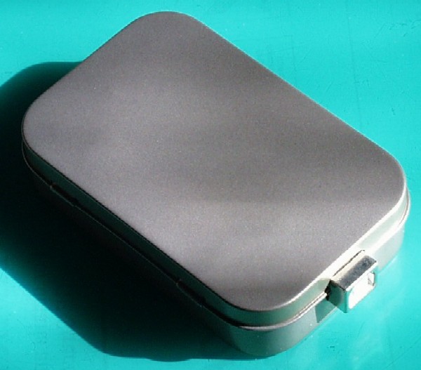
Next I powder coated the Altoids tin with a metallic silver finish.
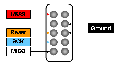
Here is the pinout for the 10 pin ISP header jack.
The AVR .hex code, USB .inf driver and other info is available from the AVR Doper Project site.
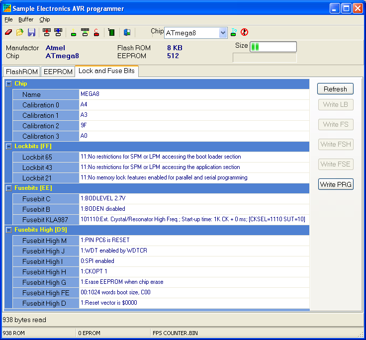
Fuse Settings: CKSEL=1110 SUT=10 (See Bascom Fuse Settings below)
I have successfully tested the programmer with the 2008-11-27 firmware. Here are my upgrading notes. The USB programmer can be used to upgrade itself if you have a spare ATMega8 chip.
Please read the  before asking questions.
AVRDude 5.3.1 and higher now supports the AVR Doper programmer.
 Also check out my tutorial on using a Raspberry Pi to program AVR chips.
Downloads:
SinaProg programming software (requires NI LabVIEW 2010 Run-Time Engine.)
Streamlined AVR Doper Eagle files.
Slightly modified version of the 2008_11_27 AVR Doper firmware to bypass the upgrade warning in AVR Studio.
The total cost of the project is about $12.
Parts List:
| Description | Qty |
|---|---|
| Atmel ATMEGA8-16PI | 1 |
| 74HC126N Quad Buffer | 1 |
| 12 MHz Crystal HC49/US | 1 |
| 28 pin IC socket | 1 |
| 14 pin IC socket (optional) | 1 |
| Resistor Carbon Film 68 Ohm 1/4 Watt 10% | 2 |
| Resistor Carbon Film 270 Ohm 1/4 Watt 10% | 1 |
| Resistor Carbon Film 1K Ohm 1/4 Watt 10% | 2 |
| Resistor Carbon Film 10K Ohm 1/4 Watt 10% | 5 |
| Resistor Carbon Film 2K2 Ohm 1/4 Watt 10% | 1 |
| Resistor Carbon Film 22K Ohm 1/4 Watt 10% | 1 |
| Resistor Carbon Film 33K Ohm 1/4 Watt 10% | 1 |
| Ceramic Radial Capacitor 22pF 50V 5% | 2 |
| Ceramic Radial Capacitor .1μF 50V 10% | 2 |
| Electrolytic Radial Capacitor 4.7μF 16V 20% | 1 |
| 3.6 Volt Low Power Zener Diode | 2 |
| 5×2 Pin Gold Straight Header .100" | 1 |
| 2 x 1 Pin Gold Straight Header .100" | 3 |
| Shunt .100" | 3 |
| Red LED | 1 |
| USB Connector | 1 |
| Single-sided Copper Clad Board 1 oz. 3.5" x 2.125" | 1 |
| Altoids 50g Tin | 1 |