
This tutorial will demonstrate how to drive and measure the speed of a brushless DC motor (BLDC) from the Raspberry Pi using a low cost electronic speed controller (ESC). An I2C numeric LED display will show the speed and a BCD push-wheel switch will allow user input as a throttle.
 WARNING: hard drive motors can spin at speeds in excess of 10,000 rpm which can be very dangerous. If a piece metal comes loose, it could be traveling over 100 mph (160 km/h) which can pierce skin or worse. Please use protective clothing and eye wear, fasten all spinning parts securely and ensure everything is safely contained.
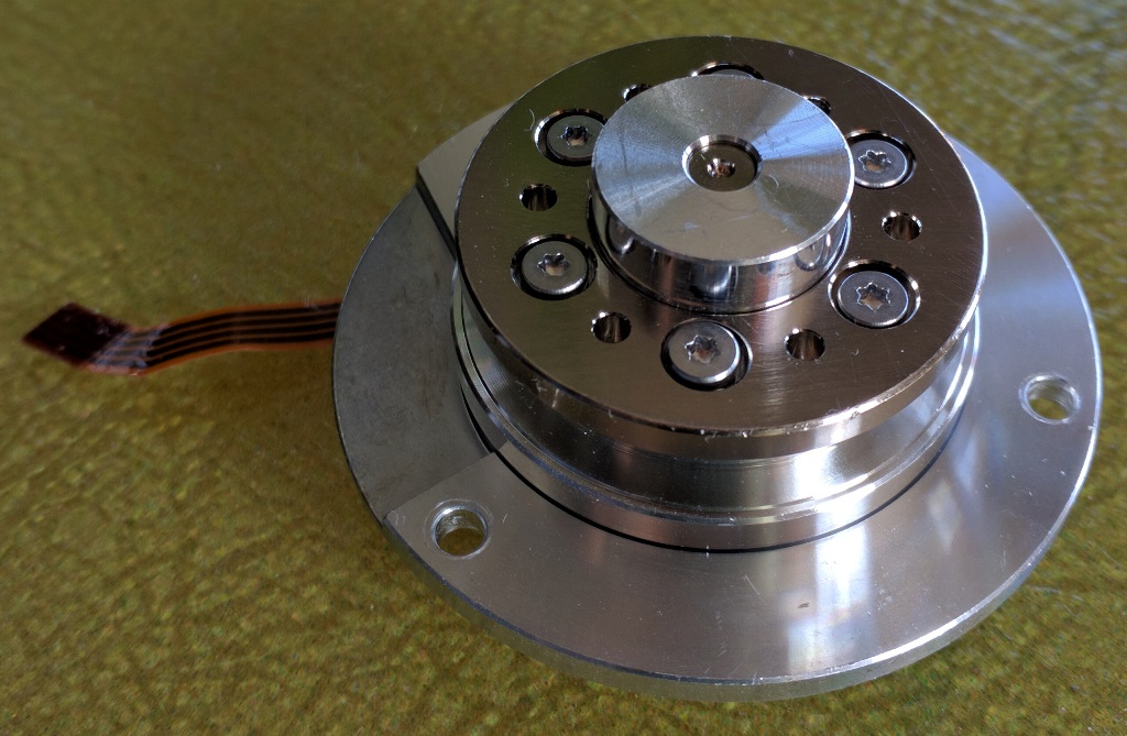
I always salvage parts from dead hard drives such as neodymium magnets, bearings, small screws, cast aluminum and 3 phase BLDC motors which have many advantages over brushed motors such as reduced noise, better efficiency, lighter weight, less EMI, more torque and longer lifespans because you don’t have brush and commutator erosion.
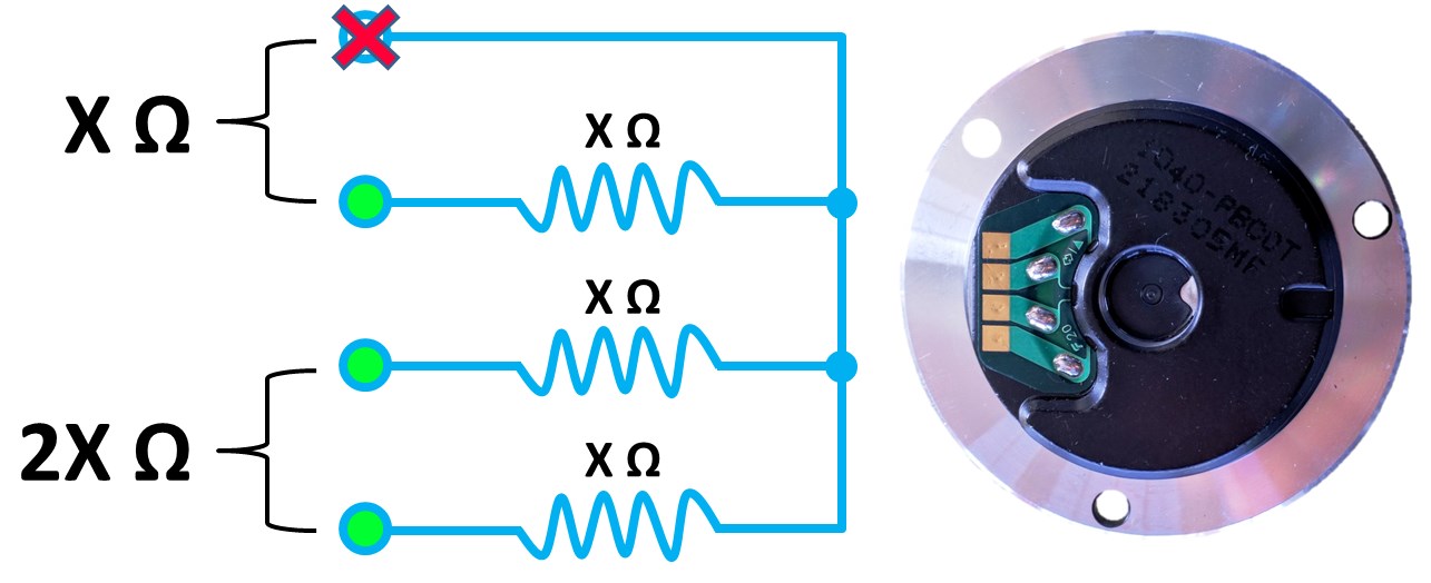
Many BLDC motors have 4 terminals but only 3 are used by an ESC. These 3 connect to the windings. The 4th is a common. A multimeter can be used to differentiate the terminals. The winding terminals have measurable resistance. Therefore the resistance between 2 winding terminals will be about twice the resistance compared to the common terminal and any of the other 3 terminals.
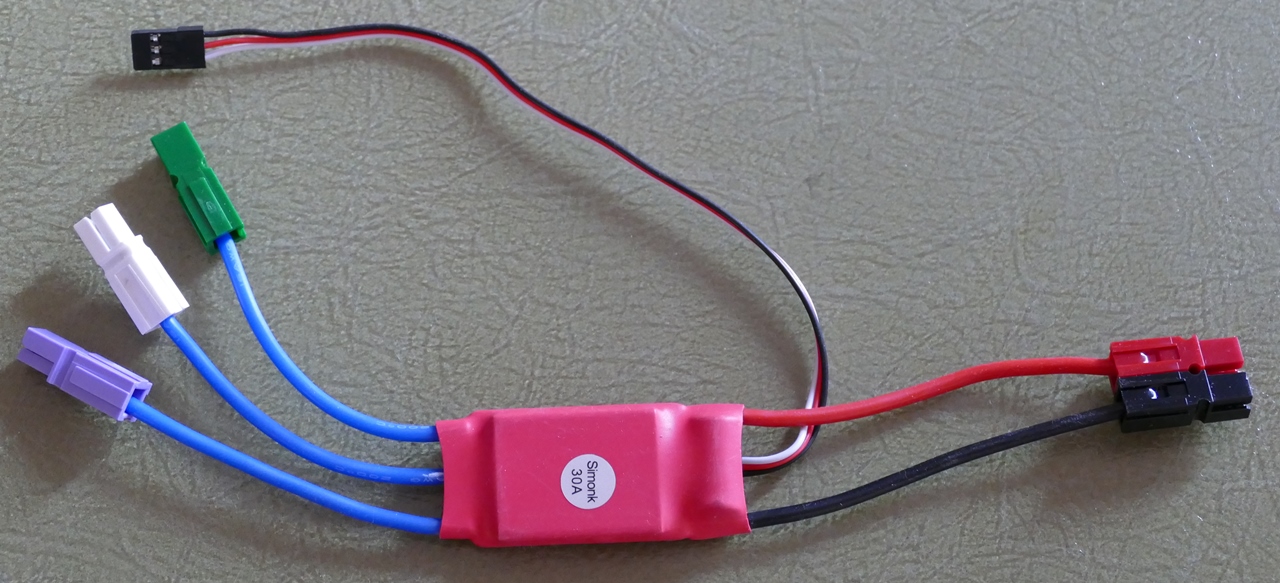
Here’s an ESC that I picked up on eBay for 3 dollars and change. I added the Anderson Powerpole connectors for easy hook ups. It’s rated for 30 amps which will easily accommodate the hard drive motor. The large red and black wires are for power. They connect to a 12 VDC power supply or battery. The 3 blue wires connect to the 3 phase brushless DC motor. The smaller 3 wires consist of a white input to control the ESC via PWM and red & black for the BEC output which provides 5 V. I was able to use the BEC to power the Pi but this cheap ESC didn’t come with any specs and it started to run very hot so I switched to a separate 5 V power supply for the Pi.
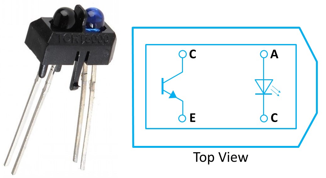
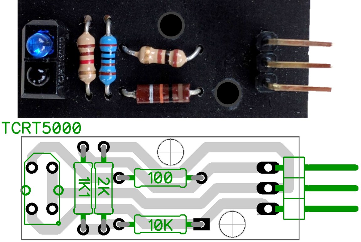
A TCRT5000 non-contact reflective optical sensor will be used to measure the motors speed. This inexpensive 4 pin package is comprised of an infrared LED and a phototransistor. The LED will shine invisible IR light on a black spinning disc with a strip of reflective tape. Each revolution of the tape will fire the phototransistor which acts like a switch allowing pulses of current to flow from the collector pin to the emitter pin. The Pi can then be used to measure these pulses to ascertain the rpm.
I milled a small breakout board for the TCRT5000. The DipTrace files can be downloaded below. The top pin is Vcc 5 V. The middle pin is ground. A 100 Ω resistor limits current to the IR LED. 1100 and 2000 Ω resistors create a voltage divider to reduce the voltage down to a Pi safe level around 3 V. The 10 KΩ resistor pulls the bottom pin up and it will get pulled low when enough light is reflected back to the sensor.
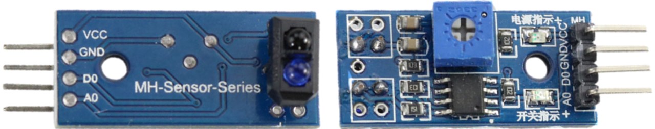
Compatible infrared reflection sensor breakout boards are available on Amazon and eBay (some under a dollar). Many have both digital and analog outputs.
The hard drive motors I salvaged can spin at just under 10,000 rpm so a 4 digit numeric LED display will work well as a tachometer. I designed and milled a simplified version of the Adafruit .56 inch 4 Digit 7 Segment LED backpack. The DipTrace files are available in the download section below.
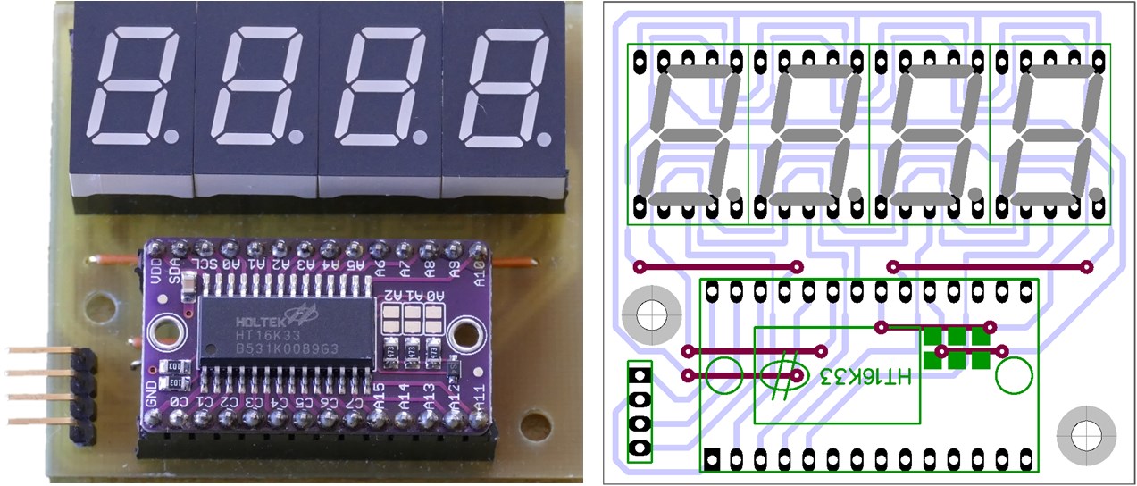
The 7 segment numeric LED’s are 0.50″ ArkLED single digit displays. They are controlled by an HT16K33 which is a great inexpensive I2C chip that can drive up to 128 LED’s. In my previous spectrum analyzer video I demonstrated the HT16K33 in more details. I have a large number of LED displays and several HT16K33 boards in my parts bin; otherwise, I probably would have just bought the Adafruit version.
A push wheel switch will be used to set the motor speed. They are also referred to as thumb wheel switches or BCD switches. The 2 buttons allows the user to select a value from zero to seven. It will provide 7 speed levels and an off position for the motor. A good salvage source is old SCSI devices such as external hard drives and tape backups. The switch has 4 wires. Three are BCD outputs and the forth is a common.
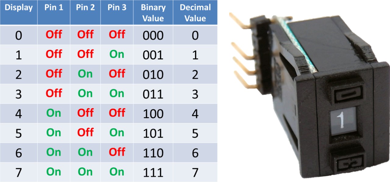
BCD stands for Binary Coded Decimal. It only uses 3 GPIO pins for 8 digits because the mechanical switch represents the selection in binary. In other words, when you select a number the switch’s output pins will change state to match the base 2 version of the displayed number. An open switch is a zero bit and a closed switch is a one bit. For example, the number 6 base 10 is equivalent to 110 in base 2. If you select 6 on the switch, the first 2 pins are on and the last pin is off with respect to the common.
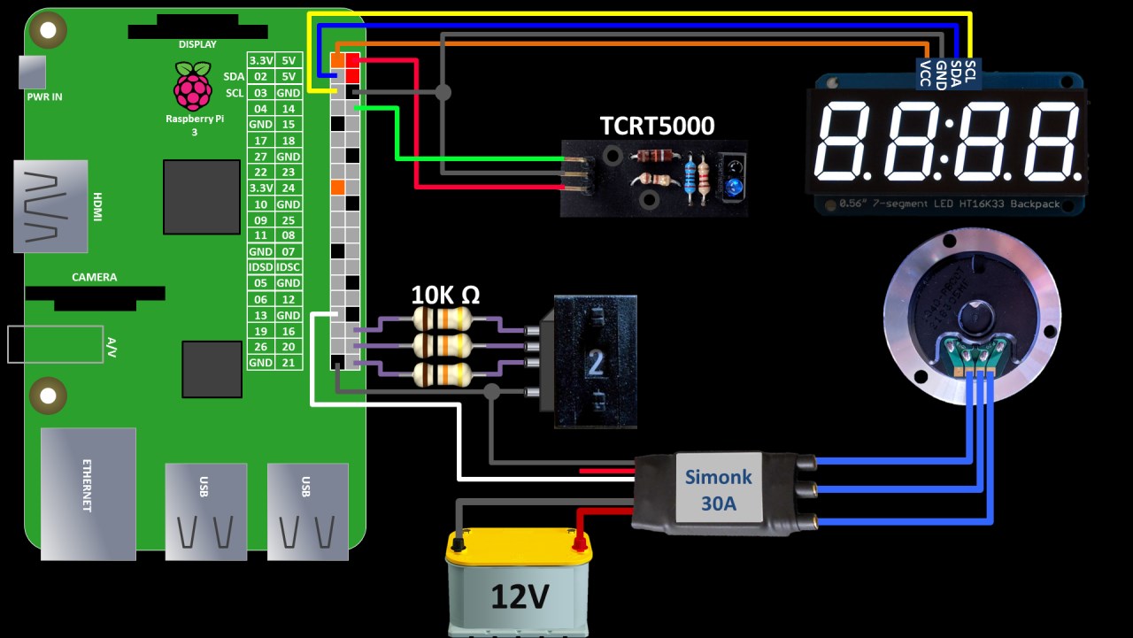
Here’s a wiring schematic. The ESC blue wires connect to the motor winding terminals. The order only affects the direction of rotation. The ESC large red & black wires are connected to a 12 VDC power source. The white input wire is connected to GPIO 13 which will control the speed via PWM. The small black BEC ground wire is connected to a Pi ground because the devices require a common ground. The small red BEC wire is left disconnected. The TCRT breakout board is connected to the Pi’s 5 V and ground pins. The sensor output is connected to GPIO 14. I2C makes wiring the LED display easy. Vcc goes to a 3.3 V pin on the Pi. The grounds are connected. SDA and SCL are connected which are GPIO 2 and 3 on the Pi respectively. The push wheel switch’s 3 outputs are connected to GPIO 16, 20 and 21. Optional 10 KΩ current limiting resistors can be used to protect the Pi against accidental shorts. The push wheel’s common terminal is often connected high to 3.3 V, but I’ll connect it to ground instead because it works well with my existing connector. It will negate the binary numbers, but this can be easily fixed in code.
Before installing the software, please make sure your Pi is up to date with sudo apt-get update and sudo apt-get upgrade.
sudo apt-get update && sudo apt-get upgrade
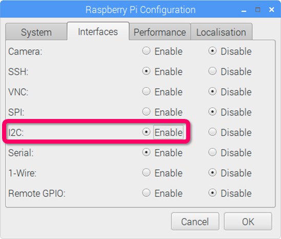
I also recommend that you use a freshly wiped Pi with the latest version of Raspbian. It comes pre-loaded with many of the libraries we’ll be using. In order to use I2C, it must be enabled. From the Raspberry Pi main menu click Preferences and then click Raspberry Pi configuration. Select the Interfaces tab and then click to enable I2C. Click OK to close.
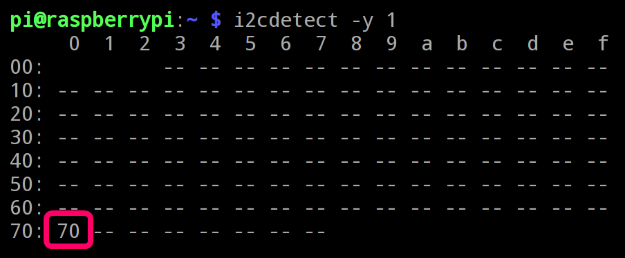
The I2C detect utility can be used to ensure that the led backpack display is properly wired. The following table shows a single I2C device at hex address 70 which is the default for the HT16K33. On older Pi’s the bus parameter might be 0 instead of 1.
Sudo pip install makes it easy to install the Adafruit LED backpack python library and its dependencies.
sudo pip install adafruit-led-backpack
The PiGPIO library will be used for pulse width modulation. It comes pre-installed with Raspbian. However, the RPM Monitor module will need to be downloaded. Unzip the single read_RPM.py file to the same folder as your code.
If you are using my backpack LED design then you will need to download QuadNumeric.py below and place it in the same folder as your code. If you’re using an Adafruit backpack then you can use the SevenSegment class that comes with the Adafruit python library that we just installed. The QuadNumeric libary is just a modified version of SevenSegment.py to accommodate a slight difference in wiring between the boards.
Here’s the code from the video:
from time import sleep
import pigpio
from read_RPM import reader
import RPi.GPIO as GPIO

# Import & initialize 4 digit 7 segment I2C display
import QuadNumeric
display = QuadNumeric.QuadNumeric(address=0x70, busnum=1)

# Optionally for Adafruit LED backpack hardware use:
# from Adafruit_LED_Backpack import SevenSegment
# display = SevenSegment.SevenSegment()

display.begin()
display.set_brightness(0)

# Set up BCM GPIO numbering
GPIO.setmode(GPIO.BCM)

# Connect to pigpio
pi = pigpio.pi()

# Calibrate ESC
ESC_GPIO = 13
pi.set_servo_pulsewidth(ESC_GPIO, 2000) # Maximum throttle.
sleep(2)
pi.set_servo_pulsewidth(ESC_GPIO, 1000) # Minimum throttle.
sleep(2)

# Set up input pins for thumbwheel switch
BCD = [16,20,21]
for pin in BCD:
    GPIO.setup(pin, GPIO.IN, pull_up_down=GPIO.PUD_UP)

# Set up RPM reader
RPM_GPIO = 14
SAMPLE_TIME = 2.0
tach = reader(pi, RPM_GPIO)

try:
    while 1:
        speed = 0
        # Loop through pins to return value of BCD counter
        for pin in BCD:
            # Left shift speed then OR by negated pin value
            speed = (speed << 1) | (1 ^ GPIO.input(pin))

        # Set ESC speed via PWM
        pi.set_servo_pulsewidth(ESC_GPIO, speed * 1000 / 7 + 1000)

        # Read RPM
        rpm = tach.RPM()

        # Show RPM on LED Display
        display.clear()
        display.print_float(rpm)
        display.write_display()

        sleep(SAMPLE_TIME)

finally:
    pi.set_servo_pulsewidth(ESC_GPIO, 0) # Stop servo pulses.
    pi.stop() # Disconnect pigpio.
    display.clear() # Clear 7 segment LED display
    display.write_display()
 WARNING: the ESC will retain calibration until it is disconnected from the power supply. If you run the above calibration code on an ESC that has already been calibrated, the motor will spin up to high speed for 2 seconds. Please note that calibration is required for the ESC to operate.
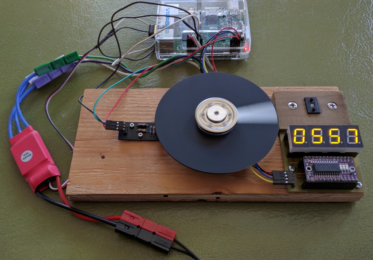
A shot of the motor spinning down.
Downloads:
Python code for ESC BLDC motor control and rpm measurement – (11-25-2016).
Dip Trace files for breakout boards – (11-25-2016).