
This tutorial demonstrates how to control bi-polar stepper motors on a Raspberry Pi in Python using a DRV-8825 stepper motor driver.
Stepper motors are brushless DC motors whose rotation is divided into a distinct number of steps which provides very accurate positional control and repeatability. This makes them very popular for 3D printers, CNC routers and robotics. Here’s a NEMA 23 570 oz-in bi-polar stepper motor from a CNC router: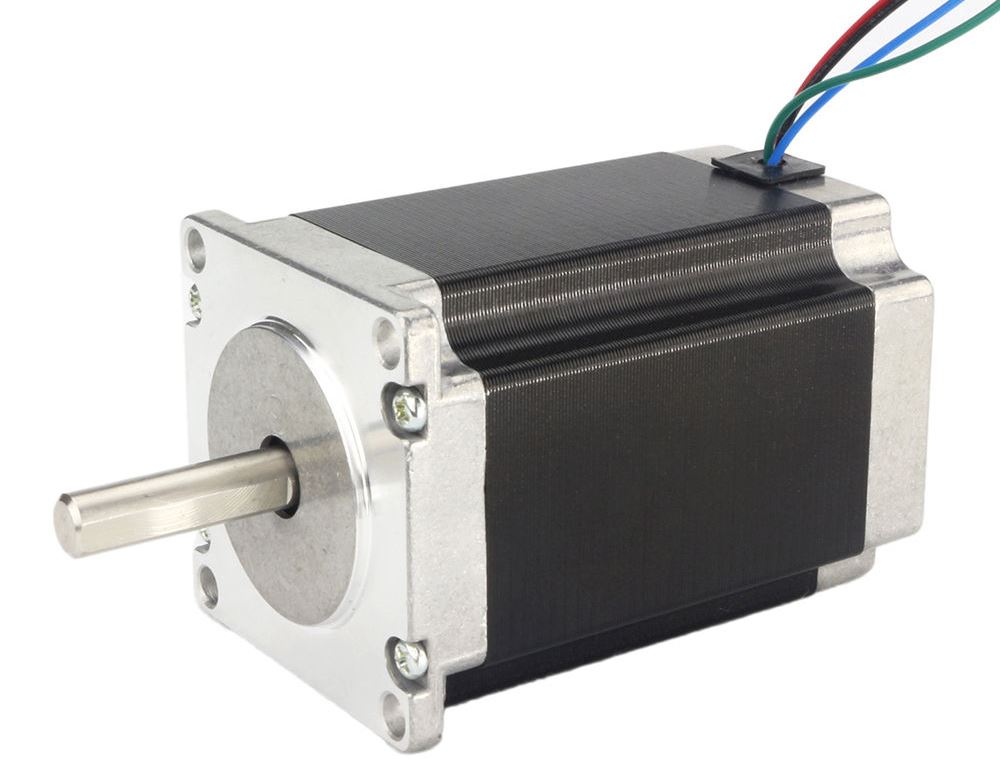
NEMA 23 just refers to the dimensions of the face plate (2.3″ x 2.3″). 570 oz-in indicates the holding torque. This measure of strength means the stationary motor can hold a weight of 570 ounces on a 1 inch radius pulley. Holding torque assumes the motor isn’t turning. When a motor turns, its torque is reduced. The faster the motor’s rotation the less torque. The stepper motor datasheet should provide a torque vs. speed curve which is helpful in selecting a motor (among many other factors). You can tell the motor is bi-polar because it has 4 wires (2 for each coil). Bi-polar stepper motors are called bi-polar because current needs to alternate directions across the coils to change the magnetic poles. This changing polarity requires a more complex driving circuit. However, there are now many low cost solutions such as the DRV-8825 bi-polar stepper driver:
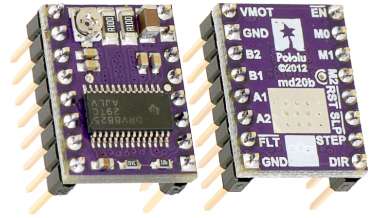
This low cost board from Pololu Robotics can control a single bi-polar stepper motor at up to 2.2 amps and 45 volts (1.5 amps without additional cooling). The maximum current output is adjustable which lets you use voltages above the stepper motor’s rated voltage to achieve higher step rates. This is often called a chopper driver. It has over-temperature, over-current, under voltage, short to ground and shorted load protection. There are 6 step resolutions from full step to 1/32 step and it has a built-in 3.3 V regulator which makes it easy to interface with the Raspberry Pi.
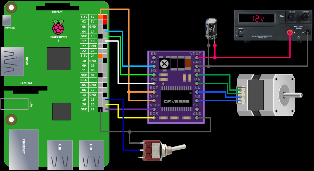
Connecting the DRV8825 is very simple. The minimal wiring requires only 2 GPIO pins. Actually 1 if you don’t care about direction. The step pin is connected to GPIO 21 and the DIR or direction pin is connected to GPIO 20. You can use any GPIO pins since they’ll be specified in the code. The ground pin is connected to a ground on the Pi. No logic voltage supply is required because the DRV8255 has a built-in 3.3 V voltage regulator. However, the RST (reset) and SLP (sleep) pins need to be pulled high by connecting them to a 3.3 V pin on the Pi because their default low states are to reset and sleep. The EN or enable pin defaults to enable so it can be left disconnected. The optional FLT or fault pin is left disconnected. It is used to detect over-current events or thermal shutdown. To control the step mode programmatically, M0, M1 and M2 are connected to GPIO 14, GPIO 15 and GPIO 18 respectively. These can also be hard wired if you don’t need to change the step mode or left disconnected if you only plan on using full step mode.
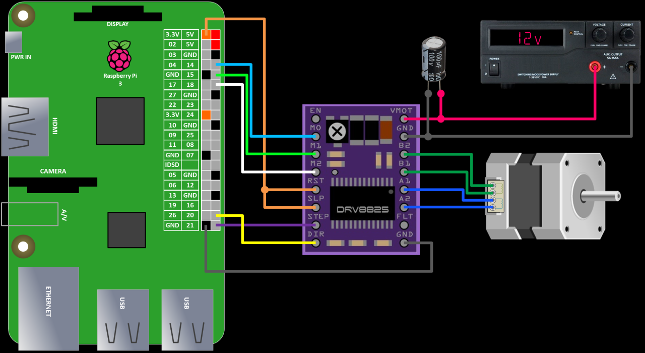
The DRV8825 requires a motor power supply between 8.2 and 45 volts. I’m using a bench power supply because the Pi cannot supply enough voltage or current. Make sure the power supply is off before connecting. The VMOT or motor voltage pin is connected to the power supply’s positive terminal. The motor ground pin is connected to the supply’s negative terminal. There’s no reverse voltage protection so double check your connections.
 Do not allow the motor power supply positive lead to touch anything other than the VMOT pin. It is at least 8.2 volts which would destroy your Pi.
The DRV8825 is susceptible to destructive voltage spikes. To protect the board, try to keep the motor power leads short and it’s important to put a minimum 47 μF electrolytic capacitor across the motor power supply as close to the DRV8255 as possible. I’m using a 100 μF cap. Put the caps negative terminal on the ground side. The negative side is identified with a vertical stripe. I usually pick a cap with double the voltage rating. For example, on a 12 volt power supply I’d use a cap rated for at least 24 volts. However, Pololu does recommend a minimum 50 volt capacitor to protect against LC spikes.
One coil of the motor is connected to A1 & A2 and the other coil is connected to B1 & B2. Please make sure the motor power supply is off when connecting or disconnecting the motor. Connecting or disconnecting a stepper motor while the driver is powered can damage or destroy the driver. Also make sure to set the maximum current before attaching the motor.
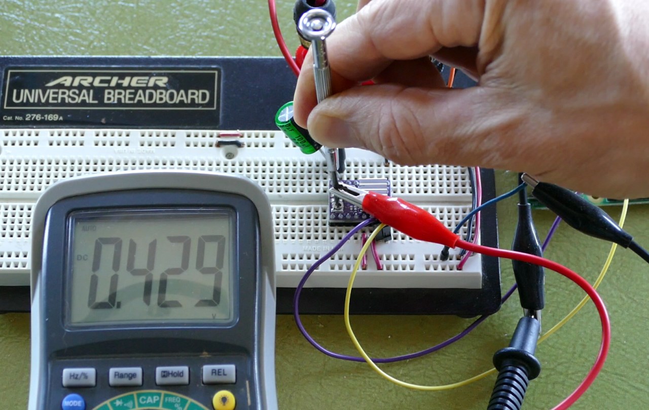
The DRV-8825 maximum current limit (I) is equal to twice the Vref or voltage reference.
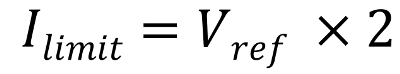
Vref can be measured using the Vref via or the Vref potentiometer. First, attach your multimeter negative probe to the DRV-8825 ground. Then use an alligator clip to attach the meter positive probe to a small metal screw driver. Now you can read the Vref while making adjustments. Setting the Vref to .429 V sets the maximum motor current to .858 A using the above formula. Please see your stepper motor datasheet to determine the peak current limit.
The DRV8825 datasheet indicates that in full step mode, the current is limited to 71% of the set maximum current. Therefore, you can set the maximum current higher than the peak for extra torque as long as you stick to full step mode.
| Mode2 | Mode1 | Mode0 | Step Mode |
|---|---|---|---|
| 0 | 0 | 0 | Full step (2-phase excitation) with 71% current |
| 0 | 0 | 1 | 1/2 step (1-2 phase excitation) |
| 0 | 1 | 0 | 1/4 step (W1-2 phase excitation) |
| 0 | 1 | 1 | 8 microsteps/step |
| 1 | 0 | 0 | 16 microsteps/step |
| 1 | 0 | 1 | 32 microsteps/step |
It’s always a good idea to monitor the stepper motor and driver board temperature. I like to use a 5 second rule. If I can touch the motor and driver board for at least 5 seconds without burning my fingers then the current is probably OK. Please note that the current can also be limited by the motor coil resistance because of Ohm’s law (V = I x R). For example, if your coil resistance is 30 Ω and your power supply is 12 V then the current will be limited to 0.4 A (12 V = 0.4 A x 30 Ω)
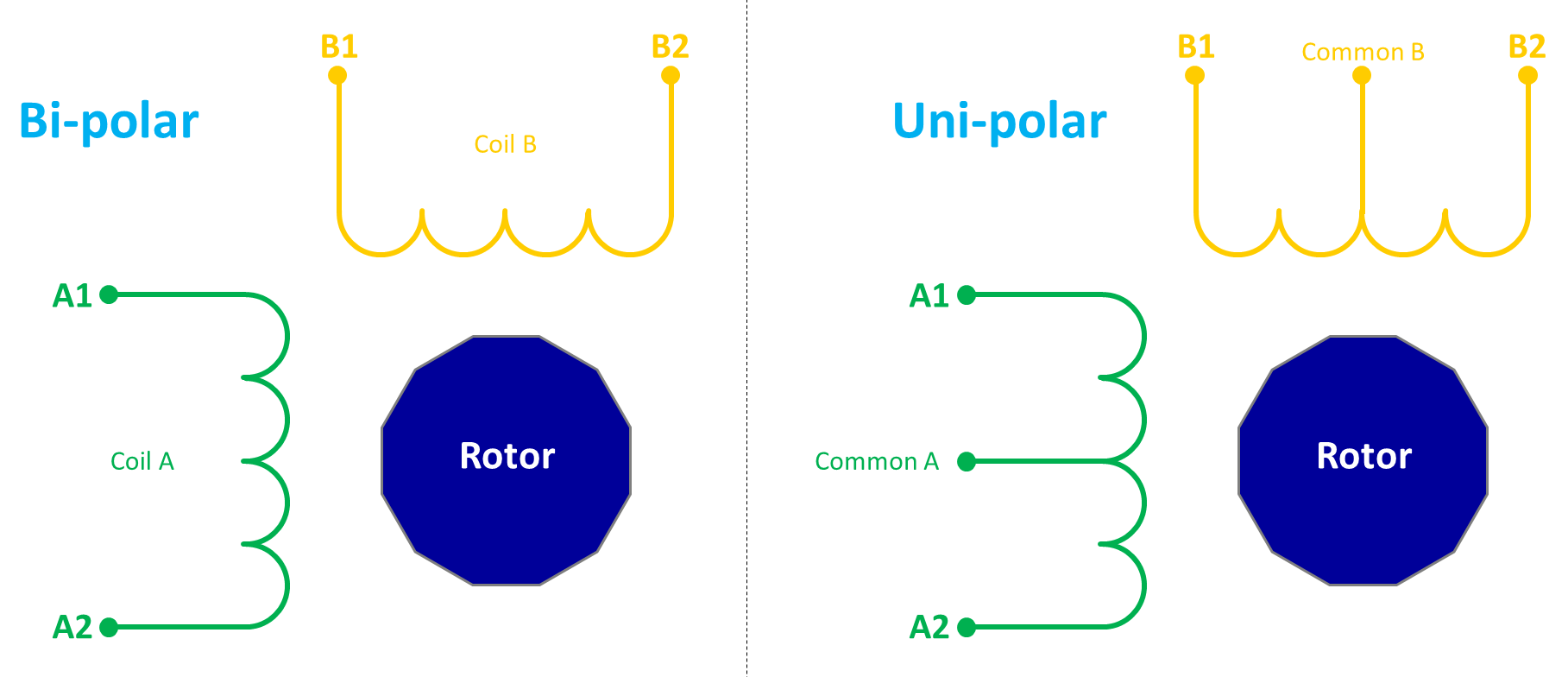
Once the maximum current is set the stepper motor can be attached. A stepper motor may have any number of coils. But these coils are connected in groups called “phases”. All the coils in a phase are energized together. 4 wire bi-polar stepper motors are 2 phase and have 2 groups of coils. The driver alternates polarity to the coils to turn the rotor. Another stepper motor type is uni-polar which have a center tap for each coil. The uni-polar driver can power either coil half to change polarity. This simplifies the circuitry as opposed to bi-polar, but it also reduces the torque because only half the coil is energized. 6 wire uni-polar motors can often be run as bi-polar by ignoring the center taps. 5 wire uni-polar have the 2 center taps connected. In order to run them as bi-polar, the connection between the center taps must be severed.
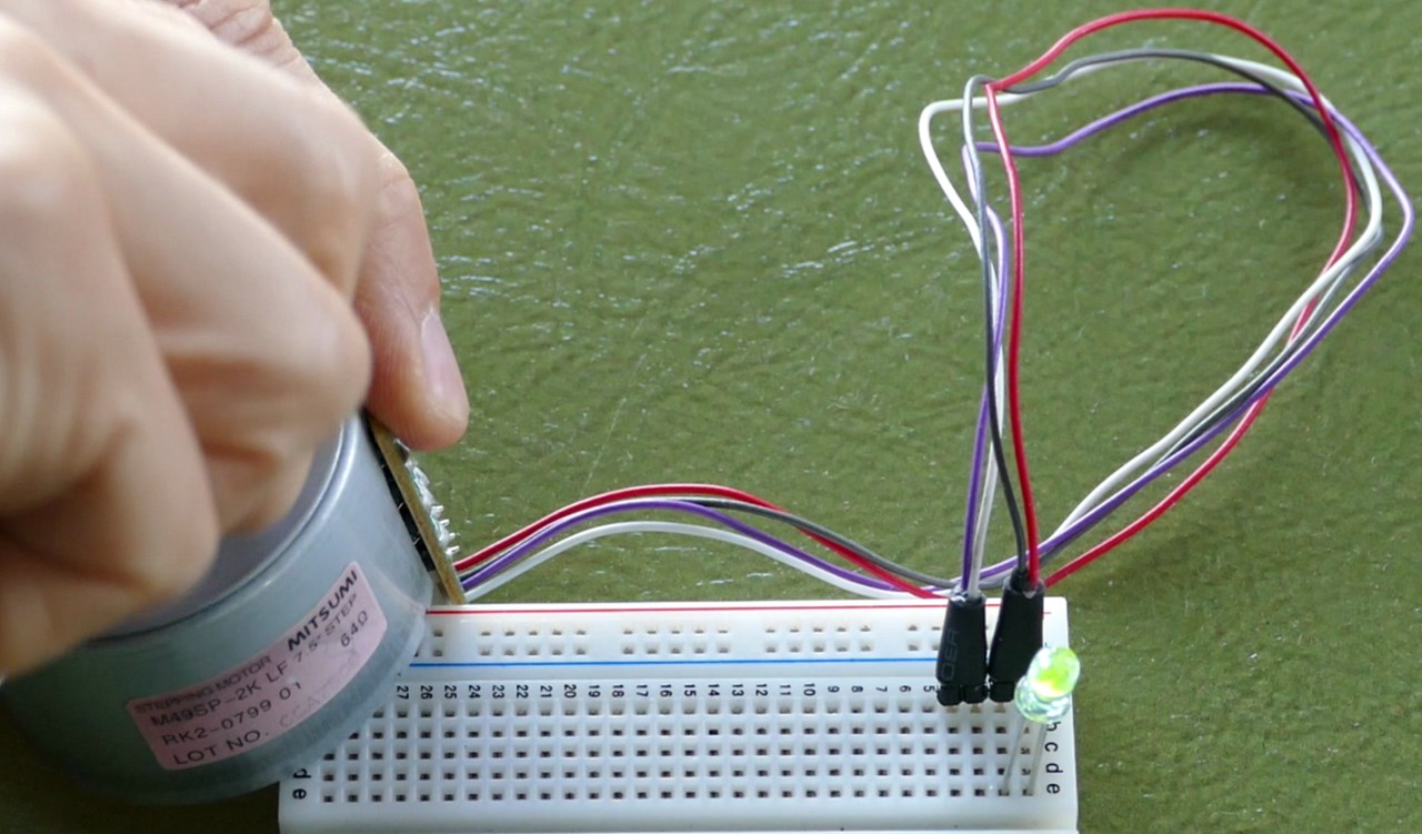
The stepper motor wires are often not labelled. One easy method to identify which wires go with which coil is to use an LED. Place an LED across any 2 motor wires. Direction doesn’t matter. Spin the motor by hand and if the LED blinks, the 2 wires are a coil. You can also use a multimeter to check for coil continuity if you don’t have an LED or if the stepper motor is too small to power the LED.
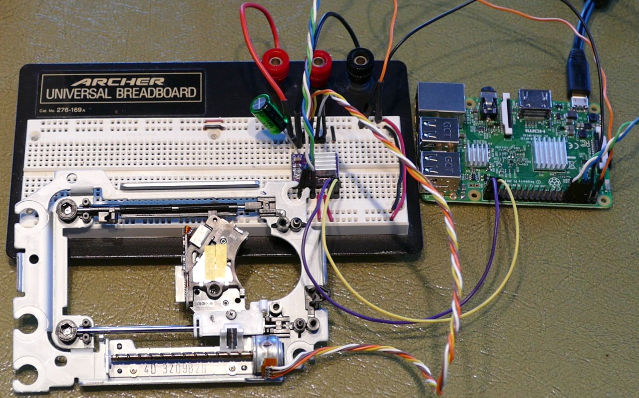
Here’s a pic of a CD drive stepper motor wired to the DRV-8825:
Before writing any software, please make sure your Pi is up to date with sudo apt-get update and sudo apt-get upgrade.
sudo apt-get update && sudo apt-get upgrade
As always I recommend you start with a freshly wiped Pi using the latest version of Raspbian to ensure you have all the necessary software.
The first Python example rotates a 48 SPR (steps per revolution) motor once clockwise and then back counter-clockwise using the RPi.GPIO library. The DIR and STEP pins are set as outputs. The DIR pin is set high for clockwise. Then a for loop counts up to 48. Each cycle toggles the STEP pin high for .0208 seconds and low for .0208 seconds. The DIR pin is set low for counter-clockwise and the for loop is repeated.
from time import sleep
import RPi.GPIO as GPIO

DIR = 20   # Direction GPIO Pin
STEP = 21  # Step GPIO Pin
CW = 1     # Clockwise Rotation
CCW = 0    # Counterclockwise Rotation
SPR = 48   # Steps per Revolution (360 / 7.5)

GPIO.setmode(GPIO.BCM)
GPIO.setup(DIR, GPIO.OUT)
GPIO.setup(STEP, GPIO.OUT)
GPIO.output(DIR, CW)

step_count = SPR
delay = .0208

for x in range(step_count):
    GPIO.output(STEP, GPIO.HIGH)
    sleep(delay)
    GPIO.output(STEP, GPIO.LOW)
    sleep(delay)

sleep(.5)
GPIO.output(DIR, CCW)
for x in range(step_count):
    GPIO.output(STEP, GPIO.HIGH)
    sleep(delay)
    GPIO.output(STEP, GPIO.LOW)
    sleep(delay)

GPIO.cleanup()
This code may result in motor vibration and jerky motion especially at low speeds. One way to counter these result is with microstepping. The following code snippet is added to the code above. The mode GPIO pins are set as outputs. A dict holds the appropriate values for each stepping format. GPIO.output sets the mode to 1/32. Note that step count is multiplied by 32 because each rotation now takes 32 times as many cycles which results in more fluid motion. The delay is divided by 32 to compensate for the extra steps.
MODE = (14, 15, 18)   # Microstep Resolution GPIO Pins
GPIO.setup(MODE, GPIO.OUT)
RESOLUTION = {'Full': (0, 0, 0),
              'Half': (1, 0, 0),
              '1/4': (0, 1, 0),
              '1/8': (1, 1, 0),
              '1/16': (0, 0, 1),
              '1/32': (1, 0, 1)}
GPIO.output(MODE, RESOLUTION['1/32'])

step_count = SPR * 32
delay = .0208 / 32
Please be aware that there are some significant downsides to microstepping. There is often a substantial loss of torque which can lead to a loss of accuracy. See the resources section below for more information.
For the next example, a switch will be added to change direction. One terminal of the switch goes to GPIO16. Another terminal goes to ground.
One issue with the last program is that it relies on the Python sleep method for timing which is not very reliable. For the next example, I’ll use the PiGPIO library which provides hardware based PWM timing.
Before use, the PiGPIO daemon must be started using sudo pigpiod from a terminal.
sudo pigpiod
The first part of the following code is similar to the first example. The syntax is modified for the PiGPIO library. The set_PWM_dutycycle method is used to set the PWM dutycycle. This is the percentage of the pulse that is high and low. The value 128 sets it to 50%. Therefore, the on and off portions of the cycle are equal. The set_PWM_frequency method sets the number of pulses per second. The value 500 sets the frequency to 500 Hz. An infinite while loop checks the switch and toggles the direction appropriately.
from time import sleep
import pigpio

DIR = 20     # Direction GPIO Pin
STEP = 21    # Step GPIO Pin
SWITCH = 16  # GPIO pin of switch

# Connect to pigpiod daemon
pi = pigpio.pi()

# Set up pins as an output
pi.set_mode(DIR, pigpio.OUTPUT)
pi.set_mode(STEP, pigpio.OUTPUT)

# Set up input switch
pi.set_mode(SWITCH, pigpio.INPUT)
pi.set_pull_up_down(SWITCH, pigpio.PUD_UP)

MODE = (14, 15, 18)   # Microstep Resolution GPIO Pins
RESOLUTION = {'Full': (0, 0, 0),
              'Half': (1, 0, 0),
              '1/4': (0, 1, 0),
              '1/8': (1, 1, 0),
              '1/16': (0, 0, 1),
              '1/32': (1, 0, 1)}
for i in range(3):
    pi.write(MODE[i], RESOLUTION['Full'][i])

# Set duty cycle and frequency
pi.set_PWM_dutycycle(STEP, 128)  # PWM 1/2 On 1/2 Off
pi.set_PWM_frequency(STEP, 500)  # 500 pulses per second

try:
    while True:
        pi.write(DIR, pi.read(SWITCH))  # Set direction
        sleep(.1)

except KeyboardInterrupt:
    print ("\nCtrl-C pressed.  Stopping PIGPIO and exiting...")
finally:
    pi.set_PWM_dutycycle(STEP, 0)  # PWM off
    pi.stop()
One caveat when using the PiGPIO set_PWM_frequency method is it is limited to specific frequency values per sample rate as specified in the following table.
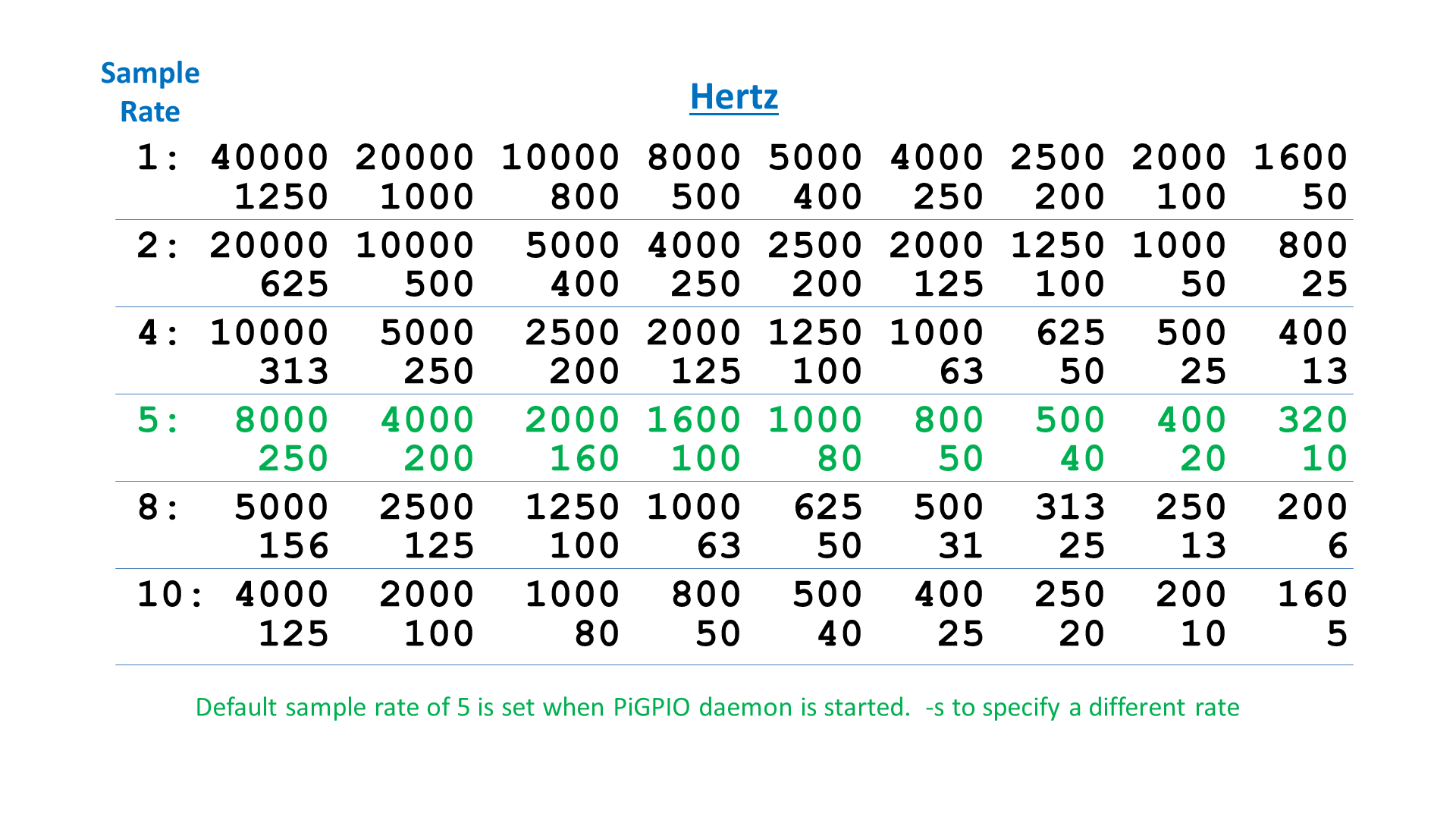
You can change the same rate using the -s configuration option when you start the PiGPIO daemon. The default sample rate is 5 which has values between 8000 and 10 hertz (see green row above). For the code example, I chose 500 Hz which is one of the values. If I had specified 600 it would have automatically dropped it down to 500. 700 would be bumped up to 800. If you need to use a frequency not found in the table, PiGPIO also allows you to use the Pi’s built in hardware PWM which is only available on GPIO pin 18. Instead of the set_pwm methods, you would to use the hardware_PWM method. It takes parameters for GPIO, frequency and duty cycle.
pi.hardware_PWM(18, frequency, duty_cycle)
One drawback to the 2nd Python example, is we only have control over speed and direction. It does not afford the ability to specify the number of steps to travel. Also switching a motor direction abruptly or accelerating too fast can lead to missed steps. A better practice is to smoothly accelerate and decelerate. This is often referred to as ramping. Both of these issues can be addressed with PiGPIO waveforms.
Currently there is a bug in the PiGPIO library related to waveform timing. A workaround is to start the PigPIO daemon with the -t option (clock peripheral) set to zero for PWM as opposed to the default PCM.
sudo pigpiod -t 0
This fixes the waveform timing. Hopefully, this bug will be fixed pretty soon. Please note that although it fixes the waveform timing it interferes with the PWM timing in the previous example and prevents the use of the hardware_PWM().
The following method generate_ramp was posted to the Raspberry Pi forum by Joan the author of PiGPIO. The method takes a variable ramp which is a list of frequency and step pairs. It then generates a chain of waveforms corresponding to the passed values. I made a few small modifications to the method such as hard coding the GPIO and clearing existing waves at the onset of the method as opposed to blocking the thread at the end to clean up.
def generate_ramp(ramp):
    """Generate ramp wave forms.
    ramp:  List of [Frequency, Steps]
    """
    pi.wave_clear()     # clear existing waves
    length = len(ramp)  # number of ramp levels
    wid = [-1] * length

    # Generate a wave per ramp level
    for i in range(length):
        frequency = ramp[i][0]
        micros = int(500000 / frequency)
        wf = []
        wf.append(pigpio.pulse(1 << STEP, 0, micros))  # pulse on
        wf.append(pigpio.pulse(0, 1 << STEP, micros))  # pulse off
        pi.wave_add_generic(wf)
        wid[i] = pi.wave_create()

    # Generate a chain of waves
    chain = []
    for i in range(length):
        steps = ramp[i][1]
        x = steps & 255
        y = steps >> 8
        chain += [255, 0, wid[i], 255, 1, x, y]

    pi.wave_chain(chain)  # Transmit chain.
Don’t worry if the method itself seems complicated because it is very easy to use. The following snippet calls generate_ramp with 6 ramp levels to slowly accelerate from 320 Hz to 2000 Hz. The steps per ramp level are exaggerated for demonstration purposes. Often a specific frequency will cause resonance and it is necessary to increase the acceleration to go through the resonance frequency quickly.
# Ramp up
generate_ramp([[320, 200],
	       [500, 400],
	       [800, 500],
	       [1000, 700],
	       [1600, 900],
	       [2000, 10000]])
 I received several questions asking if you can control multiple stepper motors. The short answer is yes but it depends on the type of precision and timing you need. For example CNC or 3D printing would probably require a dedicated controller. Please take a look at PyCNC. Otherwise, you are only limited by the number of available GPIO pins.
Resources:
DRV-8825 Missing Microsteps with Solution (link hijacked)
How to prevent step losses with Stepper Motors
Microstepping Myths and Realities
Pololu DRV-8825 FAQ
Stepper and BLDC Motor Interactive Animations
All Python Code from Video – Released 6/4/2017