
Here is a short video tutorial on how to interface an HC-SR501 PIR motion detector with the Raspberry Pi and display notifications on an LCD display. It builds on my first LCD display tutorial and my inputs & interrupts video. So I suggest you also check them out.
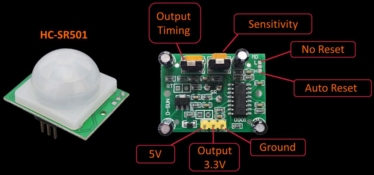
The HC-SR501 is a passive infrared (PIR) motion sensor. In addition to the 3 pin header, there are 2 pots to adjust timing and sensitivity.
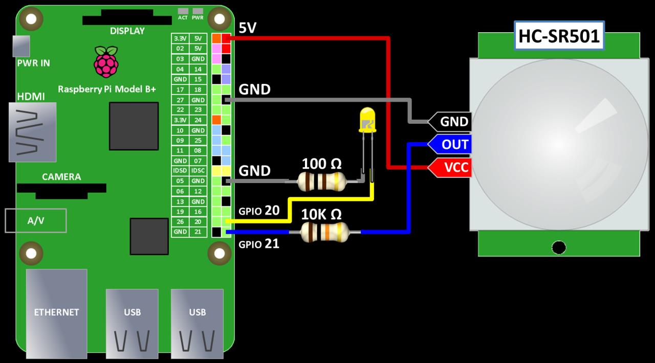
The sensor is powered from one of the Pi’s 5 V pins, but it outputs 3.3 V so it is safe to hook up directly to any of the Pi’s GPIO pins. I’m using GPIO 21. The 10 KΩ resistor is not necessary. It is only a precaution. I like to use resistors to protect the Pi GPIO inputs which can be damaged if accidently connected to 5 V or higher. The optional LED is connected in series with a resistor to GPIO 20. With a 100 Ω resistor, GPIO 20 is sourcing about 11.8 mA to power the LED. You don’t want to exceed 16 mA on any GPIO pin. LED’s have very different current requirements so please check your datasheets. I always test the current on a breadboard with a multimeter prior to connecting to the Pi.
The sample code imports the Adafruit CharLCD library to drive the LCD display. It also uses the RPI library to handle the interrupts and requires version 0.5.2a or higher. The GPIO.setup() method is used to set GPIO 21 as an input. The internal pull down resistor is activated because the motion sensor output goes high upon detection. The pull down insures the default state of the pin is low. The pull down is not necessary if your sensor already pulls the output pin low in the no motion state. GPIO.setup is used again to configure GPIO 20 as an output to drive the LED indicator. The motionSensor() callback method is fired when the motion sensor output changes state (high to low or low to high). In either state the LCD display is cleared and the LED indicator is turned off. In addition, if there is a rising state which indicates motion, then the LCD display shows a message and the LED is turned on. The GPIO.add_event_detect() method initializes the interrupt which fires the above callback method. The GPIO.both parameter is passed because the method should be called when motion is detected and when the HC-SR501 times out. I increased the bounce time to 300 ms from 150 ms in the video to optimize the performance. It is important to execute the GPIO.cleanup() method when the program exits to free up resources and prevent errors.
from Adafruit_CharLCD import Adafruit_CharLCD

lcd = Adafruit_CharLCD(rs=26, en=19, d4=13, d5=6, d6=5, d7=11, cols=16, lines=2)
lcd.clear()

from time import sleep
import RPi.GPIO as GPIO
GPIO.setmode(GPIO.BCM)     # set up BCM GPIO numbering

# Set up input pin
GPIO.setup(21, GPIO.IN, pull_up_down=GPIO.PUD_DOWN)

# Set up LED output
GPIO.setup(20, GPIO.OUT)

# Callback function to run when motion detected
def motionSensor(channel):
    lcd.clear()
    GPIO.output(20, GPIO.LOW)
    if GPIO.input(21):     # True = Rising
        global counter
        counter += 1
        lcd.message('Motion Detected\n{0}'.format(counter))
        GPIO.output(20, GPIO.HIGH)

# add event listener on pin 21
GPIO.add_event_detect(21, GPIO.BOTH, callback=motionSensor, bouncetime=300)
counter = 0

try:
    while True:
        sleep(1)         # wait 1 second

finally:                   # run on exit
    GPIO.cleanup()         # clean up
    print "All cleaned up."