
This tutorial builds my first LCD display tutorial so I recommend you watch it first. I received a request to combine inputs with an LCD display so I made the following video for the Raspberry Pi that demonstrates polling switches connected to GPIO pins and interrupt callback functions:
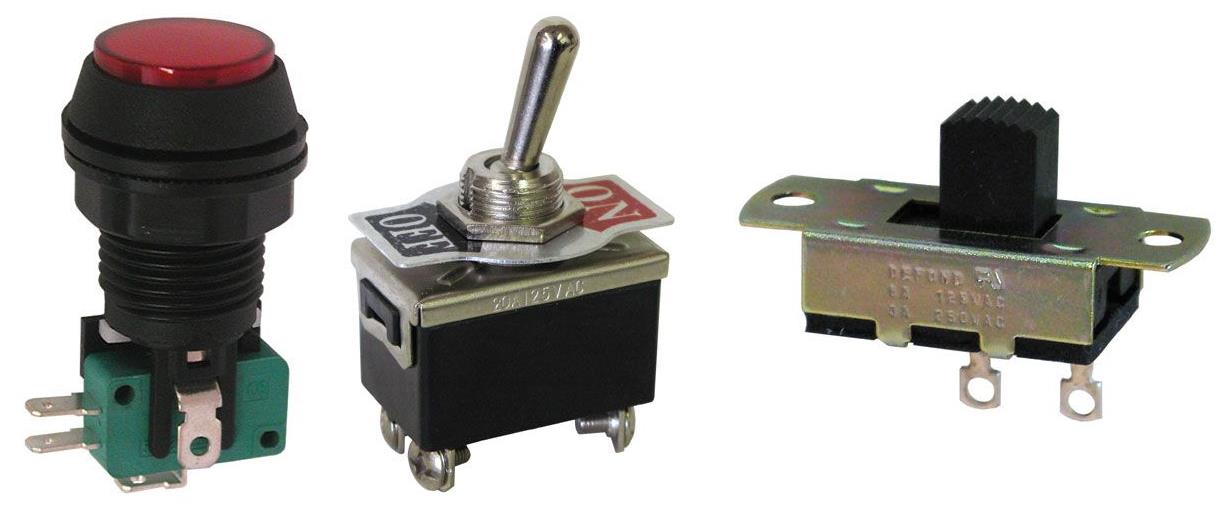
An on/off switch is one of the most basic types of inputs and they come in many varieties such as pushbutton, toggle, sliding, etc.
Switches are easy to connect to the Raspberry Pi. One terminal of the switch is connected to ground and the other terminal is connected to any GPIO pin. A pull-up resistor is used on the GPIO side to insure the pin defaults to a high state when the switch is off. Activating the switch grounds the GPIO pin to a low state. The Python GPIO.input() method can read the state of the pin and will return true if the pin is high and false if the pin is low.
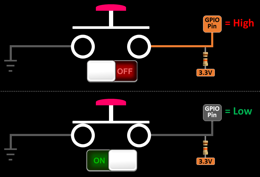
The Pi GPIO pins have internal pull-up resistors which can be activated when the pin is set up. Therefore, you don’t have to add any external resistors as in the circuit above. The pins can also be configured with internal pull-down resistors which insures a default low state.
The RPi library is used to control and monitor the GPIO pins. You can install both Python versions using sudo apt-get install:
sudo apt-get install python-rpi.gpio python3-rpi.gpio
The code in the video requires a minimum of version 0.5.2a. You can determine which version you have with the following python code:
import RPi.GPIO as GPIO
print GPIO.VERSION
Make sure you launch Idle with super user privileges which is required to access the GPIO. (Update: super-user privileges are no longer required for GPIO access with the latest version of Raspbian.) The Idle IDE no longer comes with the latest version of Raspbian. It has been replaced by the Thonny Python IDE.
/usr/bin/gksu -u root idle
The LCD display wiring differs from my first video as show below. You can use any 6 GPIO pins for RS, Enable and D4-D7. I usually select pins that will facilitate filming and programming. Also the pinouts of LCD displays can vary as well as the power requirements for the backlight so please chec V without a resistor. Even if your display supports 5 V you might want to add a resistor or variable resistor to control the brightness. The same holds true for the contrast pin. I normally use variable resistors for both.
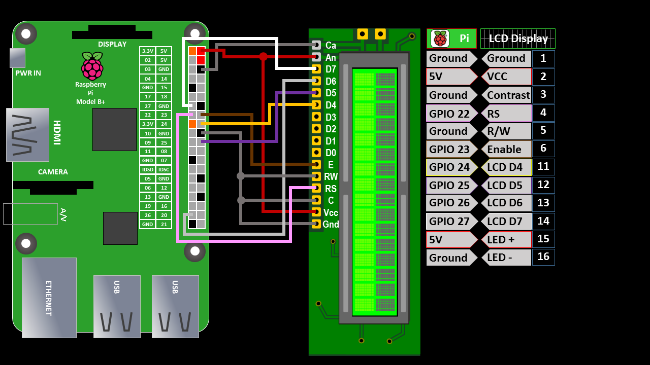
The wiring is different from my video and Adafruit has made breaking changes to the CharLCD library since the video. Here is the updated code to declare an lcd:
lcd = Adafruit_CharLCD(rs=22, en=23, d4=24, d5=25, d6=26, d7=27, cols=16, lines=2)
My first example uses polling to check the state of a switch. The GPIO.setup() method sets GPIO pin 16 to an input and turns on the internal pull-up resistor. The GPIO.input() method in the main program loop reads the state of the pin connected to the switch every second and displays the results on an LCD display. A result of 1 indicates the pin is high and the button is not pressed. A zero indicates the pin is low and the button is pressed.
from Adafruit_CharLCD import Adafruit_CharLCD

lcd = Adafruit_CharLCD(rs=22, en=23, d4=24, d5=25, d6=26, d7=27, cols=16, lines=2)
lcd.clear()

from time import sleep
import RPi.GPIO as GPIO
GPIO.setmode(GPIO.BCM)     # set up BCM GPIO numbering

# Set up input pin
GPIO.setup(16, GPIO.IN, pull_up_down=GPIO.PUD_UP)

try:
    while True:
        if(GPIO.input(16) == 1):
            lcd.message('Pin 16 = 1 HIGH\nButton Released')
        else:
            lcd.message('Pin 16 = 0 LOW\nButton Pressed')
        sleep(1)         # wait 1 second
        lcd.clear()

finally:                   # run on exit
    GPIO.cleanup()         # clean up
    print "All cleaned up."
This is a very easy way to monitor a switch. The disadvantage is that there can be button lag or missed presses depending on the speed of the loop and the other code running. Faster loops produce better results but also use up more CPU resources. A better way to check a switch is with interrupts. This method interrupts the program when the state of GPIO pin changes and fires a callback function. The following code uses the GPIO.add_event_detect() method to add an interrupt on GPIO 16 that fires a method called buttonPressed as soon as the switch is released. This is a rising state because the switch is rising from 0 to 3.3 V. Notice that the main program loop is empty, because everything is handle by the interrupt and the callback.from Adafruit_CharLCD import Adafruit_CharLCD
from Adafruit_CharLCD import Adafruit_CharLCD

lcd = Adafruit_CharLCD(rs=22, en=23, d4=24, d5=25, d6=26, d7=27, cols=16, lines=2)
lcd.clear()

from time import sleep
import RPi.GPIO as GPIO
GPIO.setmode(GPIO.BCM)     # set up BCM GPIO numbering

# Set up input pin
GPIO.setup(16, GPIO.IN, pull_up_down=GPIO.PUD_UP)

# Callback function to run in another thread when button pressed
def buttonPressed(channel):
    lcd.clear()
    global counter
    counter += 1
    lcd.message('Button Pressed\n{0}'.format(counter))

# add event listener on pin 16
# event will interrupt the program and call the buttonPressed function
GPIO.add_event_detect(16, GPIO.RISING, callback=buttonPressed, bouncetime=150)
counter = 0
try:
    while True:
        sleep(1)         # wait 1 second

finally:                   # run on exit
    GPIO.cleanup()         # clean up
    print "All cleaned up."
For the hexadecimal calculator, I’m using a Grayhill 84BC1-005 keypad which has 16 pushbuttons. Here is the pinout:
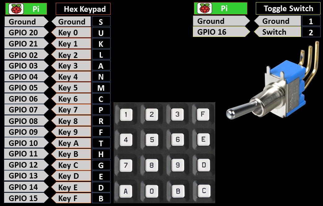
I use a channel list to set up 17 inputs at once. There is a callback function toggleChanged() for the toggle switch. It needs to fire when the switch changes in both directions so the GPIO.BOTH parameter is passed during setup to catch falling and rising events. The function either displays the results or clears the display. There is another callback function keypadPressed() to handle the keypad button presses. A loop is used to generate the 16 keypad button interrupts.
from Adafruit_CharLCD import Adafruit_CharLCD

lcd = Adafruit_CharLCD(rs=22, en=23, d4=24, d5=25, d6=26, d7=27, cols=16, lines=2)
lcd.clear()
lcd.blink(True)            # turn on blinking cursor

row = 0                    # variable to hold row position
col = 0                    # variable to hold column position
line = ''                  # variable to hold line display

from time import sleep
import RPi.GPIO as GPIO
GPIO.setmode(GPIO.BCM)     # set up BCM GPIO numbering

# Set up all input pins (pass tuple of GPIO pins)
channel_list =[20,21,2,3,4,5,6,7,8,9,10,11,12,13,14,15,16]
GPIO.setup(channel_list, GPIO.IN, pull_up_down=GPIO.PUD_UP)

# Set initial display line
if GPIO.input(16):
    row = 0    # First Line
else:
    row = 1    # Second Line
lcd.setCursor(col, row)

# Callback function to run in another thread when toggle switch state changes
def toggleChanged(channel):
    global col, row, line
    col = 0
    if GPIO.input(16):     # True = Rising = First Line (decimal)
        print "Toggle to Decimal row"
        row = 0
        if not line:
            lcd.clear()
        else:
            lcd.setCursor(col, row)
            lcd.message('{0:d}'.format(int(line, 16)))
    else:                  # False = Falling = Second Line (hex)
        print "Toggle to Hex row"
        row = 1
        if not line:
            lcd.clear()
            lcd.setCursor(col, row)
        else:
            lcd.setCursor(col, row)
            lcd.message('{0:x}'.format(int(line)))
    line = ''

# Callback function to run in another thread when keypad pressed
def keypadPressed(channel):
    if channel == 20 or channel == 21:
        channel -= 20      # Adjust for keys 0 & 1 on GPIO 20 & 21

    global col, row, line
    if row == 0 and channel > 9:
        pass               # First line is for decimal (no hex)
    elif col < 16:
        key = '{0:x}'.format(channel)  # Format key to hex string
        line += key
        print 'Keypad pressed: ' + key
        lcd.setCursor(col, row)
        lcd.message(key)
        col += 1
    else:
        print 'Line full: ' + line
        dec = int(line, 16)

# listen for changing edge on toggle switch (both directions)
# event will interrupt the program and call the toggleLine function
GPIO.add_event_detect(16, GPIO.BOTH, callback=toggleChanged, bouncetime=300)

# exclude toggle pin
channel_list.pop();
# loop through channels and add event for each button on keypad
for pin in channel_list:
    GPIO.add_event_detect(pin, GPIO.RISING, callback=keypadPressed, bouncetime=150)

try:
    while True:
        sleep(1)         # wait 1 second

finally:                   # run on exit
    GPIO.cleanup()         # clean up
    print "All cleaned up."