
This project builds a custom MicroPython Wi-Fi caller ID OLED display that sniffs network broadcast packets from a hardware call monitoring and blocking device.
I started this project to help protect an elderly family member with dementia from predatory robocallers and telephone spammers. Before starting this project I tried Nomorobo and a popular hardware call blocker but neither helped. Many unwanted calls are from cons who constantly spoof the caller ID. Finding a solution has been challenging because the octogenarian is a true Luddite. She refuses to own a smart phone or a computer and has never been on the Internet. Her technology is capped at these 20th century telephones and anything newer is confusing and intimidating.
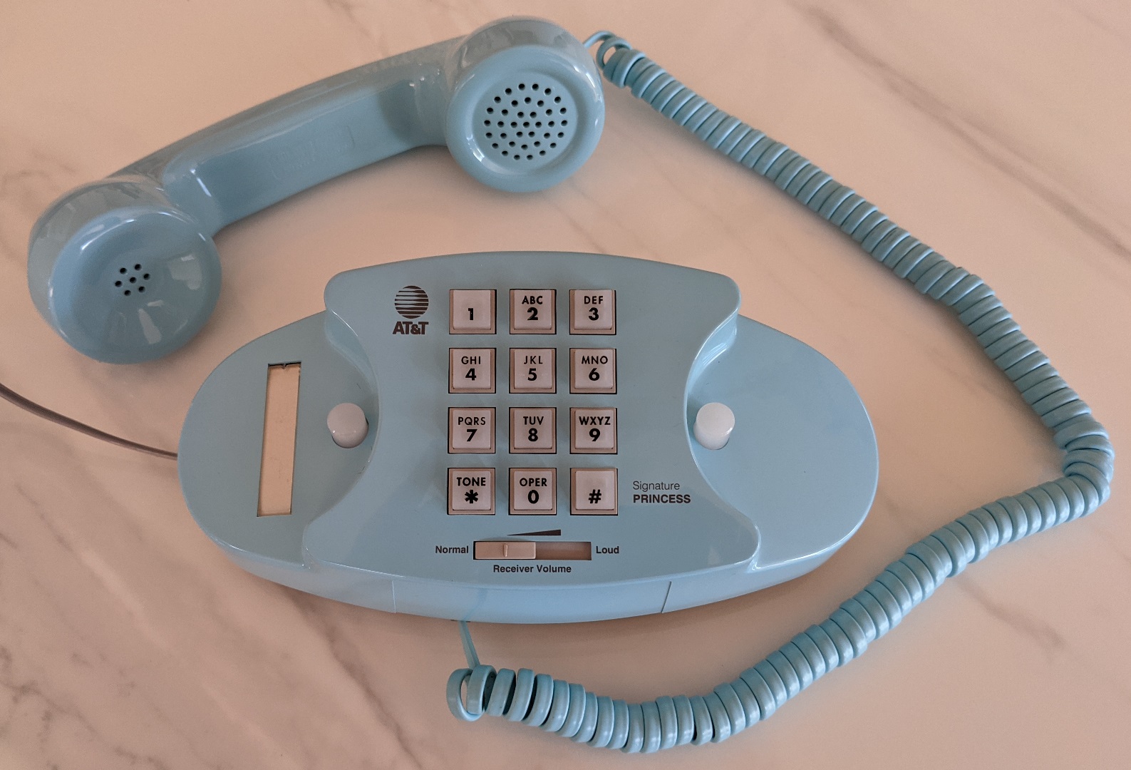
My initial plan was just to build a customer caller ID module with a very easy to read large OLED display that would only show the caller’s name and no other text that might distract her. My first prototype also had an RGB NeoPixel which illuminates green or red signaling if it’s safe to answer the phone.
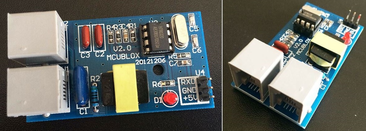
I was going to use an HT9032D module which is a common chip for parsing caller ID. However, I was a bit reluctant because it is probably against the law to connect any uncertified Terminal Equipment to the Public Switched Telephone Network.
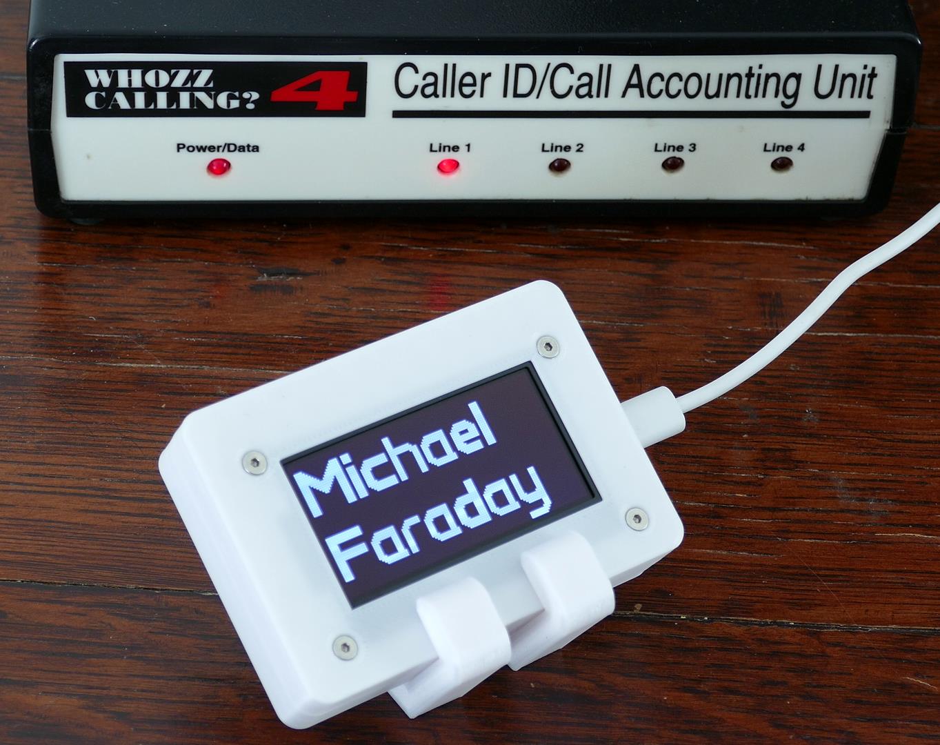
Fortunately, I found a used Whozz Calling? 4 commercial caller ID unit on eBay for $15 US.
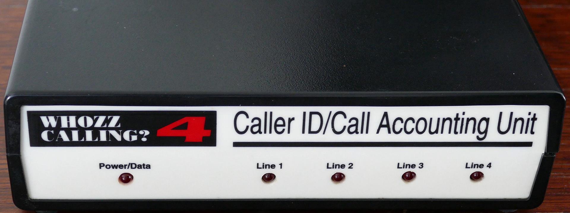
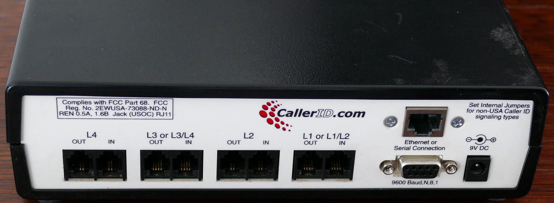
The device has all the necessary government certifications. It supports 4 lines but I only need one. There’s a serial port which can be connected to a computer or microcontroller for monitoring or configuring the device, but what’s even better is there is an Ethernet port which broadcasts caller ID data along with a lot of other information over a local area network. This greatly simplifies the implementation and isolates anything I build from the phone company. The box requires 9 volts DC but the power adapter wasn’t included. One pitfall is the barrel jack needs to be negative tipped which is less common. I cut a positive tipped power adapter and swapped the positive and negative leads.
Since the device is network enabled, any Wi-Fi capable microcontroller should be able to sniff the transmitted caller ID information. I selected an older Wemos ESP32 because I had several in my junk drawer.
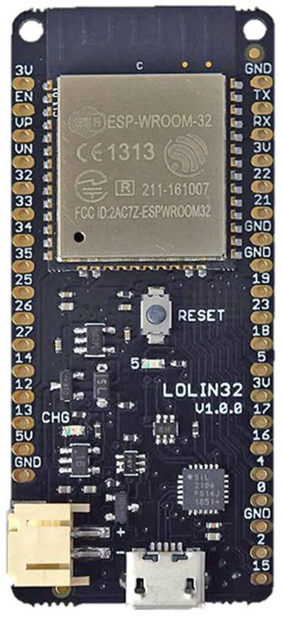
I’ve used these boards in several of my previous tutorials on how to set up and write MicroPython code for the ESP32. These older boards have the Wroom-32 chips that don’t have the additional PSRAM found in the Wrover versions. Nonetheless, they should be adequate for this simple project. The only other required component is a good quality screen.
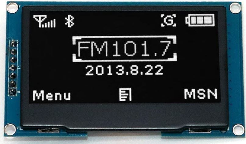
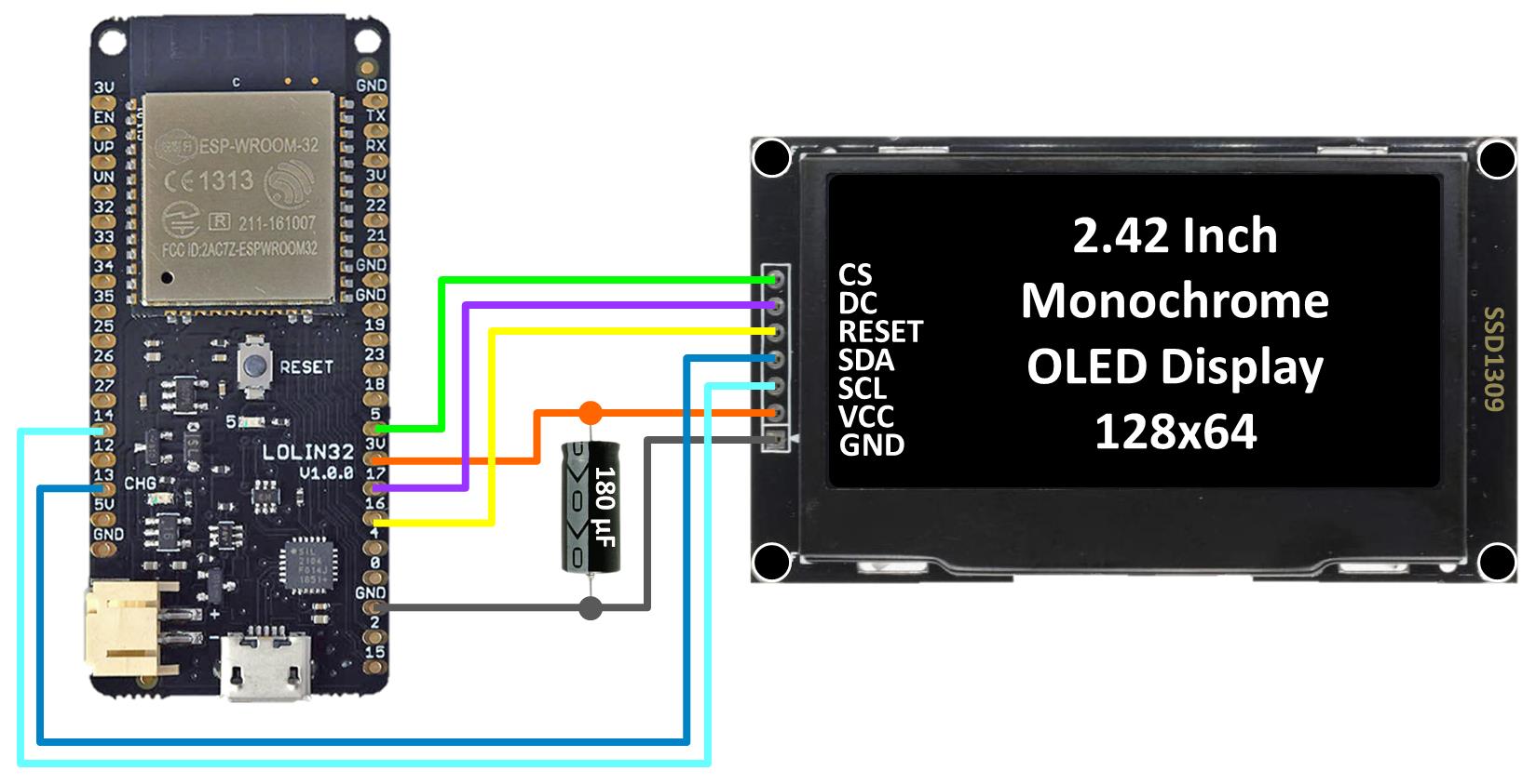
I selected a 2.42 inch monochrome OLED display with white text on a black background. OLED’s have excellent contrast even in a sunlit room. They also have extremely wide viewing angles. The resolution is a bit low at 128×64 pixels but more than adequate for large text. This 3.3 V display has an SSD1309 driver with a fast SPI interface. Therefore, it’s easy to connect to an ESP32.
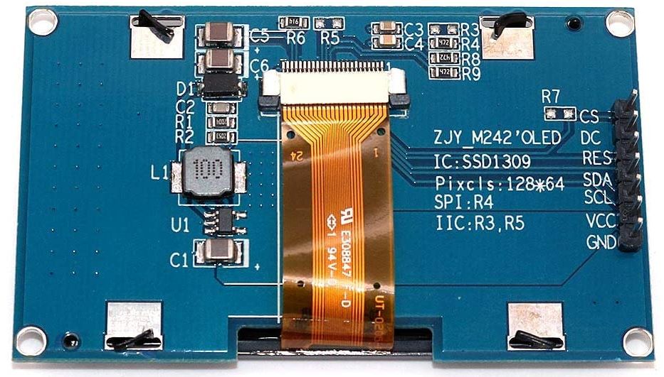
The ground from the display is connected to a ground on the ESP32. The display VCC pin is connected to a 3.3 V pin on the ESP32. SCL (serial clock) is connected to GPIO14 which is the ESP32’s HSPI serial clock. SDA (serial data) is connected to GPIO13 which is the HSPI MOSI. RST (reset) is connected to GPIO16. DC (data/command) is connected to GPIO17. CS (chip select) is connected to GPIO5. I found it necessary to add a 180 μF capacitor between VCC and ground because the big display can stress the 3.3 V supply enough to brown out the ESP32.
I created a case in SketchUp to hold the OLED display and the ESP32. The micro-USB jack will be accessible from a slot on the side. A hole in the bottom of the case will allow the reset button to be pressed with a paper clip.
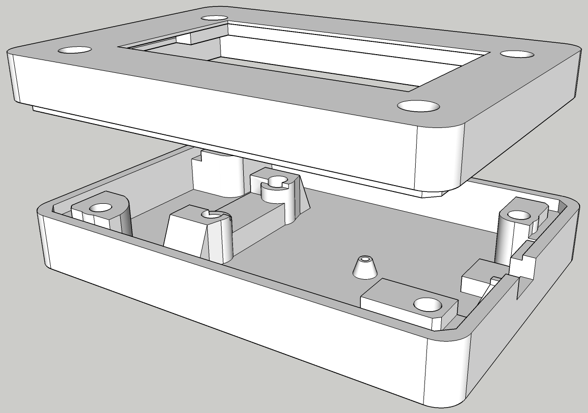
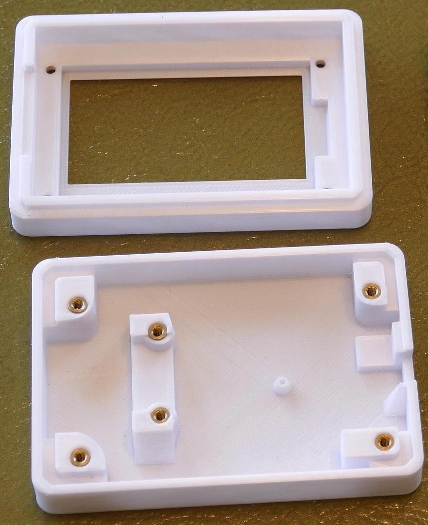
The top cover and bottom of the case are printed in white PLA. Four threaded brass inserts retain the display and the cover. The other 2 inserts secure the ESP32.
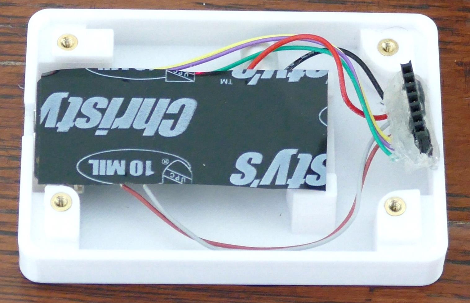
I soldered a right angle female header to the ESP32 along with a 180 μF capacitor.
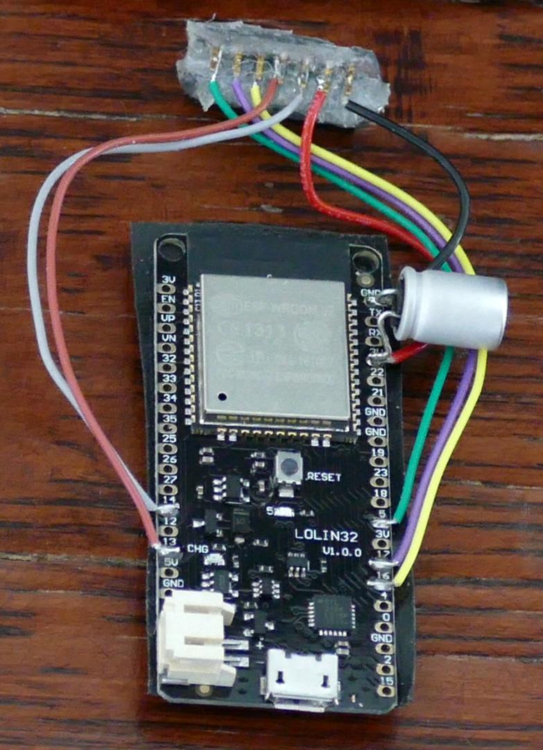
10 mil tape is applied to the back to insulate the ESP32 board from the display PCB. The ESP32 fits in to the bottom of the 3D printed case. Its micro-USB port is accessible via the slot on the left to provide 5 V power.
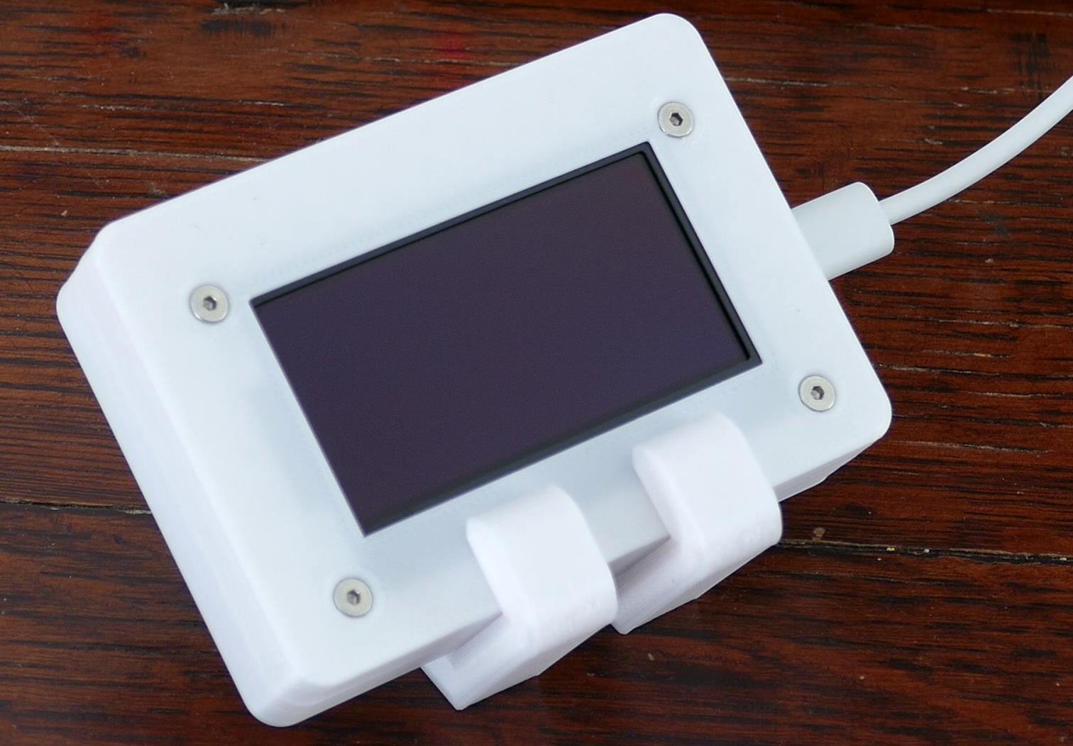
The display plugs into the female header and fits into the top cover which snaps tightly into the bottom. Four M2.5 flat head socket screws secure the top cover and the OLED in place. I also printed 2 legs for the case. Since the displays are wireless, they can be placed anywhere in the house. They don’t necessarily need to be by a telephone. Also the Wemos ESP32’s have Lipo battery charging circuits so battery power is an option too.
I wrote a MicroPython library for the SSD1309 and posted it to GitHub. The library supports drawing lines, shapes, images and text. The repo is very similar to my other MicroPython display libraries such as the SSD1351 and ILI9341 which I covered in detail in previous tutorials. Also the repo contains many examples and the code is well documented.
The MicroPython caller ID program starts with several import statements. From Select import Select. This library supports monitoring platform-specific input/output operations such as networking. From socket import socket which affords access to low level networking operations such as broadcast packets. From sys import modules which lets you reference loaded python modules. From time import sleep. From machine import Pin, SPI and Timer to control ESP32 GPIO pins, SPI interfaces and hardware timers respectively. From network import WLAN and station interface to monitor the status of the WIFI connection. From ssd1309 import Display. This is my OLED display library and from XGLCD Font import XGLCD Font for loading and drawing fonts.
"""Caller ID program."""
from select import select
from socket import socket, AF_INET, SOCK_DGRAM
from sys import modules
from time import sleep
from machine import Pin, SPI, Timer
from network import WLAN, STA_IF
from ssd1309 import Display
from xglcd_font import XglcdFont
Next a few constants are defined. Port is set to 3520. This is the UDP port number that the Caller ID device uses for broadcasting. Buffer size is set to 128. This is the maximum length of the broadcast packets in bytes. Display width is 128 pixels. Display Delay is 60,000 milliseconds which will display messages for a 1 minute duration on the OLED.
PORT = const(3520)  # Caller ID broadcasts on UDP port 3520
BUFFER_SIZE = const(128)  # Maximum broadcast packet < 128 bytes
DISPLAY_WIDTH = const(128)  # Width of LCD display
DISPLAY_DELAY = const(60000)  # Display caller ID for 1 minute
Several constants define the caller ID data position in the broadcast message. There’s data for line number, call type incoming or outgoing, indicator for start or end of call, duration, checksum, ring count, time of the call and of course the phone number and caller name.
PHONE_LINE = const(0)
CALL_TYPE = const(1)  # I=Incoming, O=Outgoing
INDICATOR = const(2)  # S or B=Call Start, E=Call End
CALL_DURATION = const(3)
CHECKSUM = const(4)  # G=Good, B=Bad
RING_COUNT = const(5)
CALL_DATE = const(6)
CALL_TIME = const(7)
CALL_AMPM = const(8)
PHONE_NUMBER = const(9)
CALLER_NAME = const(10)
SPI is instantiated and set to 10 MHz on the HSPI bus. An OLED display is initialized by passing the SPI bus and the pins for DC, CS and Reset. The display is cleared.
spi = SPI(1, baudrate=10000000, sck=Pin(14), mosi=Pin(13))
display = Display(spi, dc=Pin(17), cs=Pin(5), rst=Pin(16))
display.clear()
A variable WLAN is used to monitor the Wi-Fi. The actual Wi-Fi connection is established in the Main.py file that runs automatically when the ESP32 boots. If the Wi-Fi connection is active then the IP address is displayed to the screen. Otherwise an invalid IP warning is displayed. The built-in MicroPython 8×8 font is used for the message.
wlan = WLAN(STA_IF)  # Display IP address while loading
if wlan.active():
    display.draw_text8x8(0, 55, wlan.ifconfig()[0])
else:
    display.draw_text8x8(0, 55, "Invalid IP")
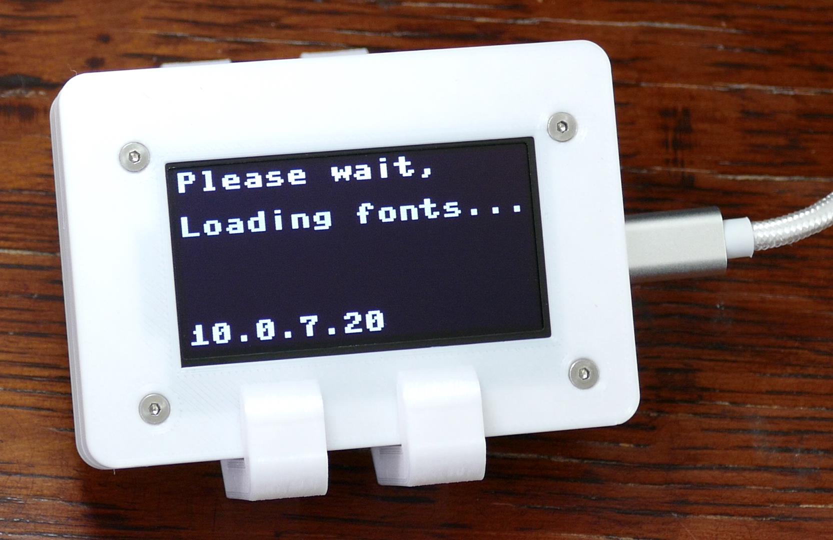
A font loading notice is also displayed. Two versions of the Pixel Perfect font are loaded which takes a couple seconds. There’s a large and a smaller version. Afterwards the display is cleared and put to sleep to save power.
display.draw_text8x8(0, 0, "Please wait,")
display.draw_text8x8(0, 16, "Loading fonts...")
display.present()

# Load fonts (takes a few seconds)
perfect_big = XglcdFont('fonts/PerfectPixel_23x32.c', 23, 32)
perfect_small = XglcdFont('fonts/PerfectPixel_18x25.c', 18, 25)
display.clear()
display.sleep()
A contacts dict is defined. It will store key pairs to associate phone numbers with contact names. A hardware timer is defined. It will control how long messages are displayed on the OLED.
contacts = {}  # Contacts dict
timer = Timer(1)  # Instantiate hardware timer
A function called load_contacts is used to load the contacts data into the dict. The comma delimited file located on the ESP32 file system is opened. A loop reads the contacts until it reaches the end of the file. Any new line or return characters are stripped. The CSV data is split on the comma into phone number and contact name and then added to the contacts dict. The phone number is the key and the name is the value.
def load_contacts():
    """Load contacts from CSV file."""
    with open('contacts.csv', 'r') as file:
        for contact in file:
            if not contact:
                return  # Break at end of text file
            contact = contact.rstrip('\n')
            contact = contact.rstrip('\r')
            contact = contact.split(',')  # Split number & name
            # Add to dict
            contacts[contact[0].strip()] = contact[1].strip()
A function called display_name_max is used to display text on the OLED and maximize the font size. The passed name parameter is measured using the larger font which will be used to draw the name if the text length is less than the display width. Otherwise, the smaller font is used.
def display_name_max(name, x, y):
    """Display name on LCD and maximize font size."

    Args:
        name (string):  name to display on LCD
        x, y (int): coordinates to draw text
    """
    if perfect_big.measure_text(name) < DISPLAY_WIDTH:
        display.draw_text(x, y, name, perfect_big)
    else:
        display.draw_text(x, y, name, perfect_small)
A function called handle_ftp allows the user to remotely enable an FTP server on the ESP32. There will be multiple displays in the house and this will allow updating the code or contacts wirelessly. The hardware timer is cleared. The display is awakened from sleep and cleared. An FTP running message is shown along with the IP address. If the FTP library is not found in the system modules then it is dynamically imported. Otherwise if the library is already loaded then the FTP server method is called. Either condition starts the FTP server which will block program operation until the FTP client disconnects. When the program resumes, the display is cleared and put to sleep.
def handle_ftp():
    timer.deinit()
    display.wake()
    display.clear()
    display.draw_text8x8(0, 16, "FTP Running")
    display.draw_text8x8(0, 32, wlan.ifconfig()[0])
    display.present()
    if 'ftp' not in modules:
        import ftp
    else:
        modules['ftp'].ftpserver()
    display.clear()
    display.sleep()
A function called timer_callback will fire when the hardware timer times out. The OLED display is cleared, put to sleep and the timer is de-initialized.
def timer_callback(t):
    """Clear display on hardware timer time out."""
    display.clear()
    display.sleep()
    t.deinit()
A function called parse_callerid decodes and processes the broadcast messages from the caller ID hardware device. Messages less than 20 bytes are skipped because they are not valid or relevant. The 21 byte message header is removed and then the bytes are decoded to a string. The space delimited data is split into a list named call data. Filter is used to remove any blank entries. If call data does not contain an entry for the phone number then the function exits.
def parse_callerid(msg):
    """Parse caller ID broadcast data."

    Args:
        msg (bytes):  caller ID message bytes.
    """

    if len(msg) < 20:
        print("invalid message")
        return  # invalid message

    msg = msg[21:].strip()  # Remove header bytes
    msg = msg.decode("utf-8")  # Decode bytes to string

    # Extract call data and remove any blank spaces
    call_data = list(filter(None, msg.split(" ")))

    if len(call_data) < PHONE_NUMBER:
        print("Non-callerid broadcast")
        return
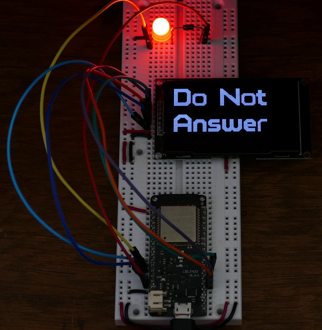
A try statement wraps the parsing to gracefully catch any errors. The caller ID hardware monitors both incoming and outgoing calls, but only the incoming information is germane. The outgoing is ignored. The indicator field indicates S for start of call or E for end of call. However, the caller ID device has a blocking feature that if enabled returns a B at the start of calls that are on an internal list that can be configured as block or bypass. Originally I was just going to create a caller ID system, but this is a great feature that can prevent all unapproved phone calls from even ringing any of the phones in the house. Therefore, the message can be skipped if the indicator does not equal B because those will be handled by a hardware blocking. The timer is cleared. The display is awakened and cleared. If the caller ID phone number is found in the contacts dict then the associated contact name is stored in a list called names which is split on the space to differentiate first and last name. Display name max is called and passed the first name. The name will be displayed on the OLED in a font that maximizes it size. If the contact has a last name then it is also displayed on the OLED again using display name max. If the caller id phone number is not in the contacts dict then something went wrong with the hardware blocking or the network broadcast. Theoretically this should never happen, but just in case, a do not answer warning message is displayed on the OLED. The hardware timer is initialized in one shot mode and passed the delay duration and the call back function. This will interrupt the program once in 1 minute and run the function that clears any displayed text and puts the OLED to sleep. So even if the program is blocked by a network socket operation, the hardware timer will still fire and ensure the display is cleaned up.
try:
    if call_data[CALL_TYPE] != "I":
        print("invalid call type: {0}".format(
                call_data[CALL_TYPE]))
        return  # Only care about incoming calls

    # B is not documented, but indicates
    # good caller when when blocking enabled
    # Otherwise S=Start of call and E=End of call
    if call_data[INDICATOR] != "B":
        return
    timer.deinit()
    display.wake()
    display.clear()
    if call_data[PHONE_NUMBER] in contacts.keys():
        # If contact exists return caller name from number
        # Split first & last names
        names = contacts[call_data[PHONE_NUMBER]].split(" ")
        display_name_max(names[0], 0, 0)  # Display first name
        if len(names) > 1:  # Last name exists
            display_name_max(names[1], 0, 32)  # Display last
    else:
        # Unknown number erroneously got past caller id block
        display.draw_text(0, 0, "Do Not", perfect_big)
        display.draw_text(0, 32, "Answer", perfect_big)
    display.present()
    timer.init(mode=Timer.ONE_SHOT, period=DISPLAY_DELAY,
                callback=timer_callback)
If an exception occurs then any error message is displayed to the OLED for debugging.
except Exception as e:
    timer.deinit()
    display.wake()
    display.clear()
    if hasattr(e, 'message'):
        print(e.message)
        display.draw_text8x8(0, 0, e.message)
    else:
        print(str(e))
        display.draw_text8x8(0, 0, str(e))
    display.present()
Here’s the main Python function that will run when the program starts. The load_contacts function is called to load the contacts from flash storage. A network socket is instantiated. The socket is bound to UDP port 3520 which is used for broadcasting by the caller ID hardware. Blocking is disabled because the Python select library will be used to monitor the socket. An infinite while loop wraps the socket monitor. A variable result is set to the results of the select method which is passed the network socket. This will block the program operation until network packets are detected on the specified port. Afterwards any received message is stored to a variable called msg. If the message equals a byte string that I designated as the FTP command then the handle_ftp function is called which will enable the ESP32 FTP server. Otherwise, the parse_callerid function is called to decode the caller ID data and update the OLED.
def main():
    """Monitor Caller ID."""
    load_contacts()  # Load contacts from flash

    s = socket(AF_INET, SOCK_DGRAM)
    s.bind(('', PORT))
    s.setblocking(0)  # Disable blocking

    print("Waiting for calls...")

    while True:
        # Monitor socket until communication
        result = select([s], [], [])
        msg = result[0][0].recv(BUFFER_SIZE)
        print(msg)
        if msg == b'^^Id-f' or msg == b'^^Id-F':  # FTP command
            handle_ftp()
        else:
            parse_callerid(msg)
When the program starts the OLED shows the loading fonts message along with the IP address. After a couple of seconds the display clears which indicates the software is waiting for calls.
Unfortunately, the caller ID hardware did not work as expected. The device is supposed to suppress the first phone ring because the caller ID data is transmitted from the phone company between the 1st and 2nd ring. There is also a feature that lets you store up to 50 phone numbers in non-volatile memory which can be used as a white list or a black list. Neither of these 2 features worked. The first ring goes through along with all blocked numbers. The device is manufactured by a company called Caller ID.com in the U.S. state of Georgia. I gave them call and I wasn’t expecting much help because it’s a 7 year old out-of-warranty unit that I bought on eBay but I was amazed at their enthusiastic customer support. I told them what I was trying to do and the owner of the company got on the phone with me. He was very hospitable and sounded like an electrical engineer. He explained that the ring suppression and blocking features were options that were not very popular and not often selected. However, he was very confident that I could make the necessary upgrades myself and proceeded to offer a trove of helpful information. It’s such a pleasure to speak with a knowledgeable business owner who takes pride in his work.
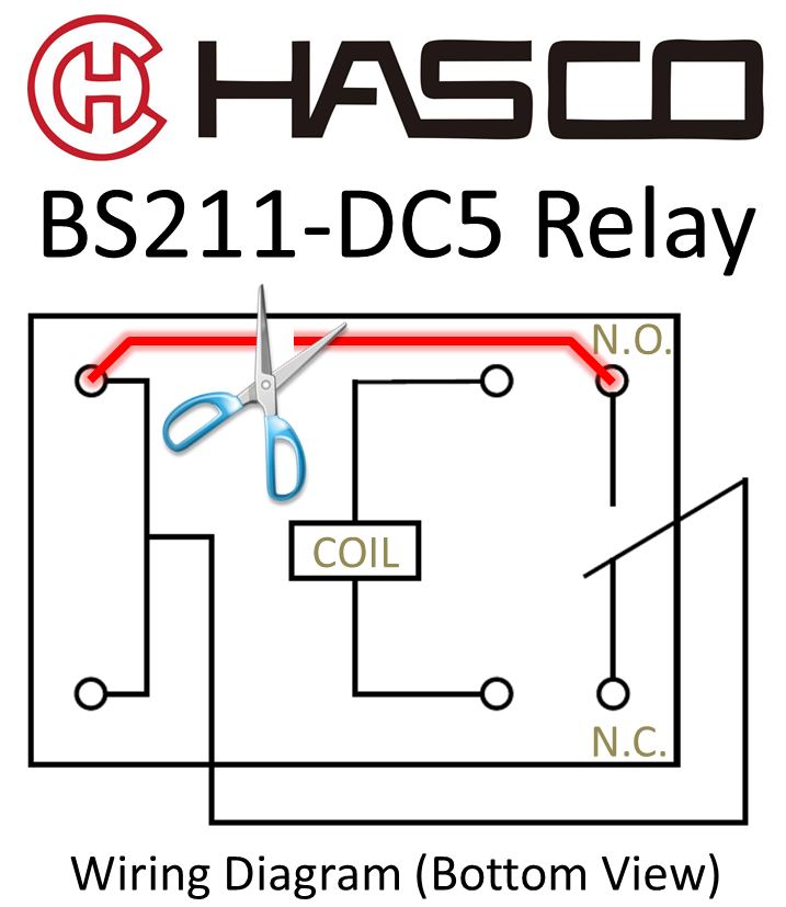
On the caller ID PCB, there are empty locations for relays marked K1 to K4 with Form C contact configurations next to each of the 4 dual phone jacks. It needs to be populated with a 5V relay (Hasco BS211-DC5). There are also empty spots for 4 NPN transistors marked Q1 to Q4 (PN2222A). Finally there are 4 empty resistor locations marked R1, R26, R43 and R60 (all with of 10K ohm values). The resistor limits the current to the base of the transistor which is used fire the coil on the relay which is used to disconnect the phone line to suppress the first ring and also block unwanted calls.
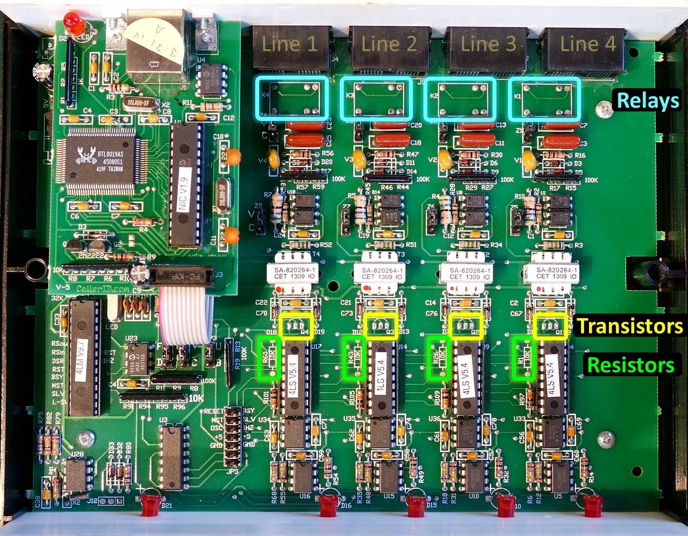
The relay is an electromagnetic switch that either connects or disconnects the phone line depending if the coil is charged. A close inspection of the caller ID PCB reveals a trace bypassing the normally open side of the relay. So regardless of the state of the relay’s armature the phone line will always be connected. It’s necessary to cut this trace for the relay to function properly. A tungsten carbide scribing pen or a box cutter works well for cutting. Afterwards, a multimeter should be used to verify that there is no continuity.
The caller ID unit can now be programmed using the provide EL Config Plus utility to suppress the first telephone ring until the caller ID data is received and also block any further rings if the caller is not on an approved list.
Downloads:
- Caller ID code (2021-01-09)
- SketchUp & STL files for case (2021-01-09)