
I received a request to make a tutorial on how to use 7 segment LED displays with a Raspberry Pi. The following video demonstrates how to use pulse width modulation (PWM) via the Pi’s DMA hardware to drive 7 segment displays.
For this video, I’m using a Kingbright DC04-11 blue dual digit display. Please note that the pinouts of LED displays vary greatly (always check your datasheets). To simplify the programming, segments A through G are wired to GPIO pins 10 to 16 in series with appropriate resistors. I start with 750 Ω resistors, then lower the resistance to get the correct brightness being careful not to exceed the Pi’s 50 mA limit. 220 Ω resistors provide good brightness and only use 12.8 mA. The common cathodes are controlled by 2 NTE2361 high speed NPN transistors connected to GPIO pins 20 and 21. You could omit the transistors and connect the common cathodes directly GPIO pins 20 and 21 as long as the total current does not exceed 16 mA. You would also have to swap the start times of the pulses because the pulses would be driving the cathodes high instead of low.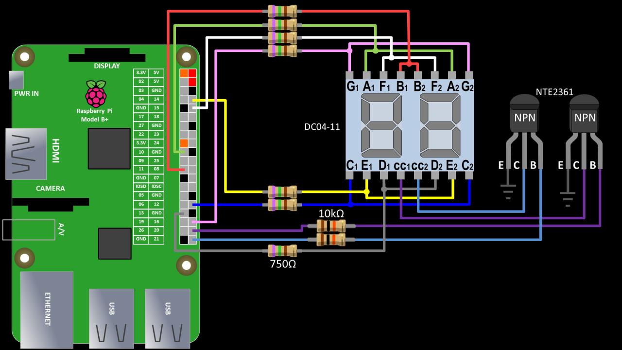
The DMA multiplexing requires the RPIO library. First make sure that the python-dev is installed:
sudo apt-get install python-dev
 The RPIO python library was recently updated to support newer model Pis. You will need to manually install the v.2 beta if you are using a Raspberry Pi 2 or newer.
I recommend that you manually install RPIO to get the latest version which as of 6/4/2016 is 2.0.0-beta1:
cd ~
git clone https://github.com/metachris/RPIO.git --branch v2 --single-branch
cd RPIO
sudo python setup.py install
Here is the Python code from the video:
from time import sleep
from RPIO import PWM

PWM.setup()
PWM.set_loglevel(PWM.LOG_LEVEL_ERRORS)
PWM.init_channel(0)

# Dictionary translating numbers to segments byte
num = {
    0:(1,1,1,1,1,1,0),
    1:(0,1,1,0,0,0,0),
    2:(1,1,0,1,1,0,1),
    3:(1,1,1,1,0,0,1),
    4:(0,1,1,0,0,1,1),
    5:(1,0,1,1,0,1,1),
    6:(1,0,1,1,1,1,1),
    7:(1,1,1,0,0,0,0),
    8:(1,1,1,1,1,1,1),
    9:(1,1,1,1,0,1,1)}

# Pulse off and on (minimum of 4 for off state = 40 μs)
pulse = {
    0:4,
    1:999}

# Start alternating 10k μs pulses for the cathodes
PWM.add_channel_pulse(0, 20, 0, 999)
PWM.add_channel_pulse(0, 21, 1000, 999)

def SetDual7Seg( value ):
    # Split passed value into separate digit integer list
    digits = map(int, "%02d" % value)

    # Set pulses for segments A-G (both digits)
    for i in range(7):
        PWM.add_channel_pulse(0, 10 + i, 0, pulse[num[digits[0]][i]])
        PWM.add_channel_pulse(0, 10 + i, 1000, pulse[num[digits[1]][i]])

for i in range(100):
    SetDual7Seg(i)
    sleep(1)

# Stop PWM for channel 0
PWM.clear_channel(0)

# Shutdown all PWM and DMA activity
PWM.cleanup()
 I was asked how to add additional digits. Here is an example with 6 digits. The pulse width is reduced from 999 to 332 to fit the 4 additional sets of pulses into the same 20K μs sub-cycle.
# Pulse off and on (minimum of 4 for off state = 40 μs)
pulse = {
    0:4,
    1:332}

# Start cathode pulses for each digit (GPIO 20 - 25)
PWM.add_channel_pulse(0, 20, 0, 332)
PWM.add_channel_pulse(0, 21, 333, 332)
PWM.add_channel_pulse(0, 22, 666, 332)
PWM.add_channel_pulse(0, 23, 1000, 332)
PWM.add_channel_pulse(0, 24, 1333, 332)
PWM.add_channel_pulse(0, 25, 1666, 332)

def SetDual7Seg( value ):
    # Split passed value into separate digit integer list
    digits = map(int, "%06d" % value)
    print(digits)
    # Set pulses for segments A-G (all digits)
    for i in range(7):
        PWM.add_channel_pulse(0, 10 + i, 0, pulse[num[digits[0]][i]])
        PWM.add_channel_pulse(0, 10 + i, 333, pulse[num[digits[1]][i]])
        PWM.add_channel_pulse(0, 10 + i, 666, pulse[num[digits[2]][i]])
        PWM.add_channel_pulse(0, 10 + i, 1000, pulse[num[digits[3]][i]])
        PWM.add_channel_pulse(0, 10 + i, 1333, pulse[num[digits[4]][i]])
        PWM.add_channel_pulse(0, 10 + i, 1666, pulse[num[digits[5]][i]])
 UPDATE: It looks like the RPIO library has been abandoned. Therefore, I created a Python example using PiGPIO. It requires the Wave PWM 2 library.
from time import sleep
import pigpio
from wavePWM import PWM

pi = pigpio.pi() # Start PiGPIO
pwm = PWM(pi)    # Use default frequency

# Dictionary translating numbers to segments byte
num = {
    0:(1,1,1,1,1,1,0),
    1:(0,1,1,0,0,0,0),
    2:(1,1,0,1,1,0,1),
    3:(1,1,1,1,0,0,1),
    4:(0,1,1,0,0,1,1),
    5:(1,0,1,1,0,1,1),
    6:(1,0,1,1,1,1,1),
    7:(1,1,1,0,0,0,0),
    8:(1,1,1,1,1,1,1),
    9:(1,1,1,1,0,1,1)}

# Start alternating 10k μs pulses for the cathodes
pwm.set_pulse_start_and_length_in_fraction(20, 0.0, 0.5)
pwm.set_pulse_start_and_length_in_fraction(21, 0.5, 0.5)

pulses = {
    0: (0.0, 0.0),
    1: (0.0, 0.5),
    2: (0.5, 0.5),
    3: (0.0, 0.999)
    }

def SetDual7Seg( value ):
    # Split passed value into separate digit integer list
    digits = list(map(int, "%02d" % value))

    # Set pulses for segments A-G (both digits)
    for i in range(7):
        pulse = pulses[num[digits[0]][i] << 1 | num[digits[1]][i]]
        pwm.set_pulse_start_and_length_in_fraction(10 + i, *pulse)
    pwm.update()

for i in range(100):
    SetDual7Seg(i)
    sleep(1)

# Clean up
for i in range(7):
    pwm.set_pulse_start_and_length_in_fraction(10 + i, 0.0, 0.0)
pwm.update()
pwm.cancel()
pi.stop()