
This tutorial demonstrates how to use serial communication on a Raspberry Pi to connect to an MPPT solar charge controller and transmit the photo-voltaic data via a python web server Rest API to web enabled devices.
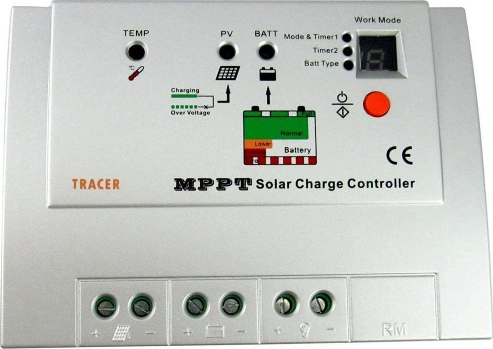
Here’s a 10 amp Tracer 1210RN Maximum Power Point Tracking (MPPT) solar charge controller. It converts the higher voltage DC output from solar panels down to the lower voltage needed to charge batteries and it does so in a very efficient manner.
Hooking it up is very intuitive. The positive and negative outputs from the solar panel connect to the corresponding terminals on the controller via 12 gauge wire with MC4 connectors. A 12 volt battery, used to power the Pi at night, is connected to the controller’s battery terminals. An inline fuse should be placed within 15 centimeters of the battery’s positive terminal.
The controller has 12 VDC load terminals which can provide power to the Raspberry Pi, as long as a step down regulator is placed in line to lower the 12 V down to 5 V.
The 12 V load outputs from the controller are connected to the inputs on the regulator. An inline fuse should be used on one of the wires. Then the 5 V output goes to the Pi’s power input. The step down regulator in the video came with a micro USB connector which fits the Pi.

I chose an old Raspberry Pi model A, because it doesn’t consume very much electricity, and although it’s under-powered, it can easily handle the 2 tasks of serial communication and web serving.
The charge controller is sold by multiple vendors such as EP Solar, SainSonic, Renogy, etc. There are several different models with different amp ratings. All models that support an optional MT5 meter LCD display use the same 3.3 V TTL communication protocol which is ideal for the Pi.
 UPDATE: Looks like the TTL versions have been discontinued, but you can still find them for sale online. Searching for 1210RN, 3215RN and 4210RN still returns a few results.
Many similar charge controllers use RS-485 protocol which is not compatible with this tutorial. If your MPPT controller does not support the MT5 display then it is likely RS-485 and would require different wiring and a different software library such as this Python repo for the RS-485 EP Solar Tracer.
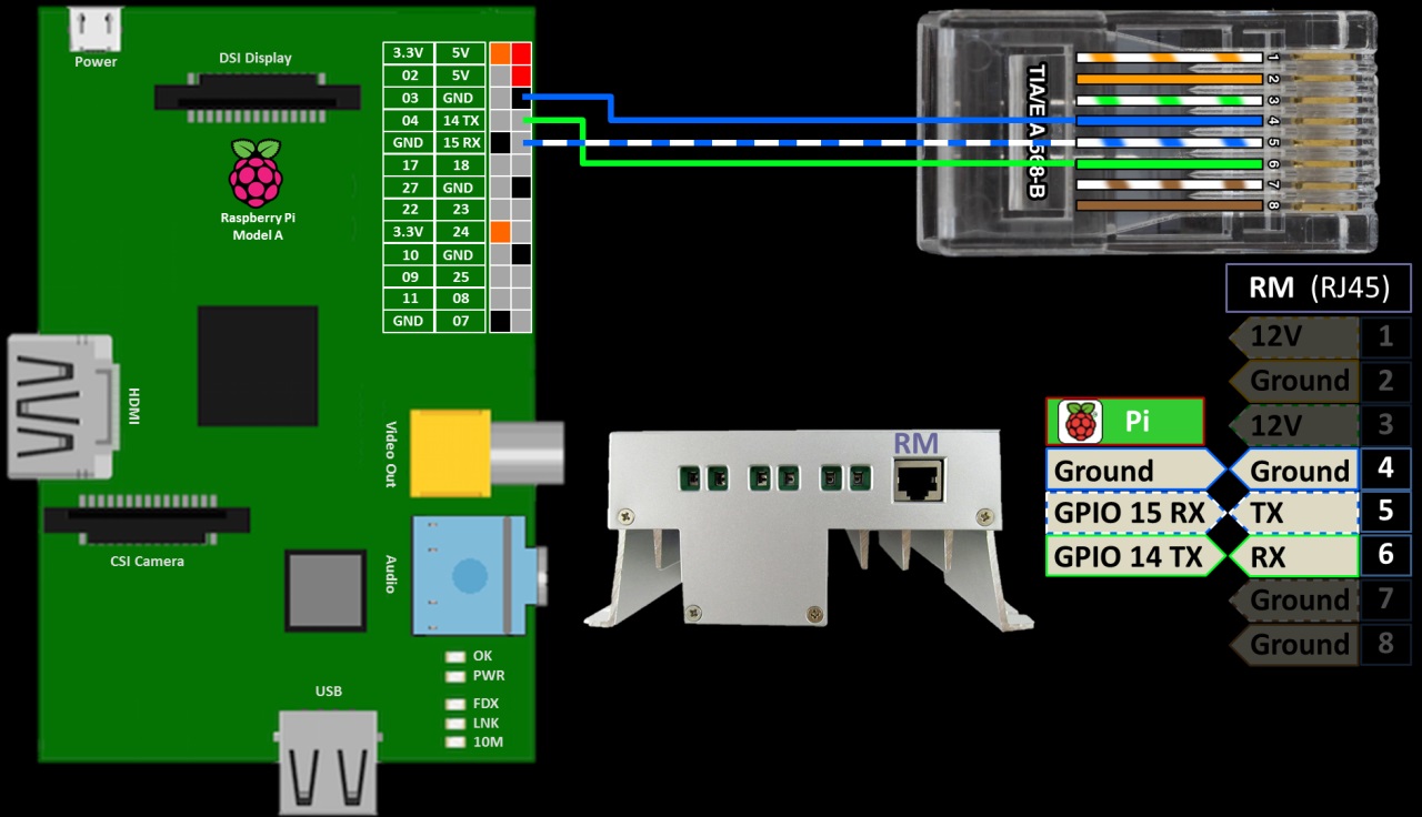
The charge controller’s remote meter (RM) port uses an RJ45 jack which takes a common computer network cable plug. The pins are 12 V on pins 1 and 3. Ground on pins 2, 4, 7 and 8. Serial transmit TX is pin 5 and serial receive RX is pin 6. To talk to the Pi we only need to connect ground, TX and RX. The RJ45 pin4 is connected to a ground on the Pi. The TX pin 5 is connected to GPIO 15 which is RX on the Pi. The RX pin 6 is connected to GPIO 14 on the PI which is TX. So transmit goes to receive and receive goes to transmit.
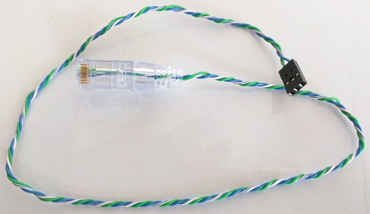
In the video I make a custom serial cable using an EZ-RJPRO HD Crimp Tool and the corresponding Cat 6+ connectors. It’s much easier and more reliable than other crimpers and it comes in very handy for networking, surveillance and home automation. However, a simple solution is just to cut one end off a network patch cable. Please double check the wiring because accidentally connecting the 12 V pins could damage the Pi. You can always use a meter to verify there is approximately 3 V from TX to ground and RX to ground. For the other side of the cable I use a 3 position female header that fits the 2.54 mm GPIO pins on the Pi.
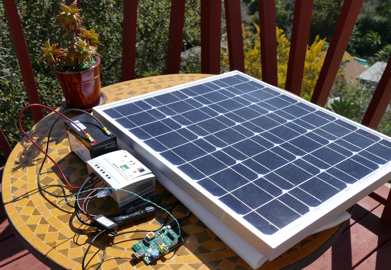
Here’s the charge control outside hooked up to 50 watt Renogy solar panel, a 12 volt lead acid battery and the Pi via a regulator.
Before installing the software, please make sure your Pi is up to date with sudo apt-get update and sudo apt-get upgrade.
sudo apt-get update && sudo apt-get upgrade
I also recommend that you use a freshly wiped Pi with the latest version of Raspbian. It comes pre-loaded with many of the libraries used in the tutorial.
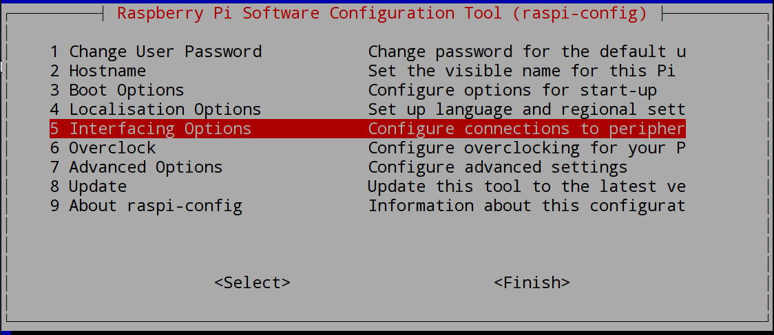
Next sudo raspi-config is used from a terminal to open the Raspberry Pi software configuration tool.
sudo raspi-config
Select Interfacing options.
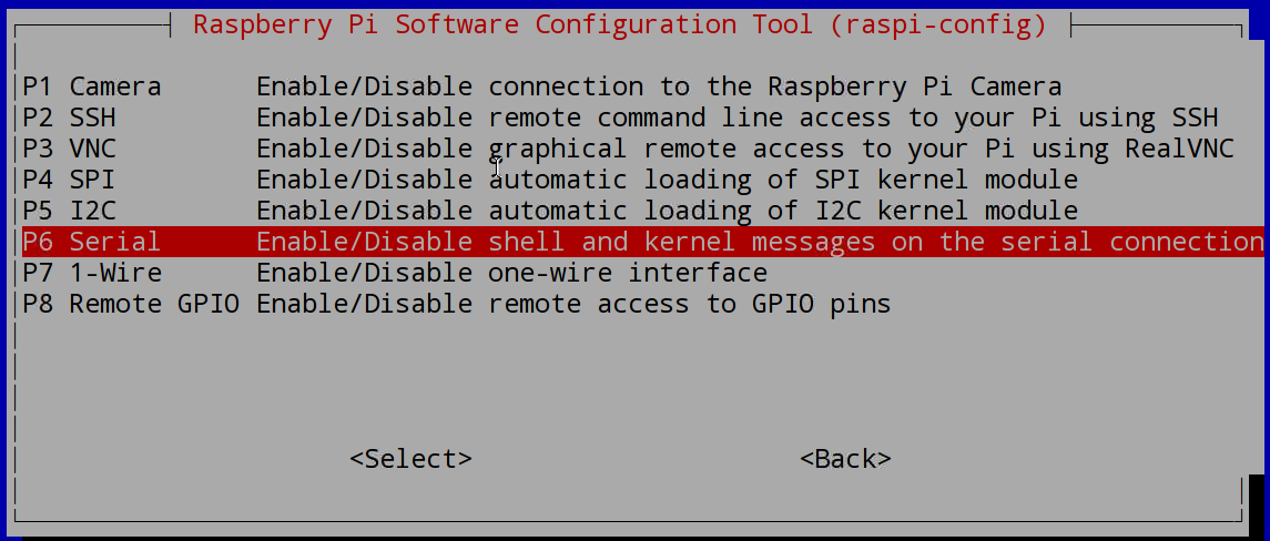
Select Serial.
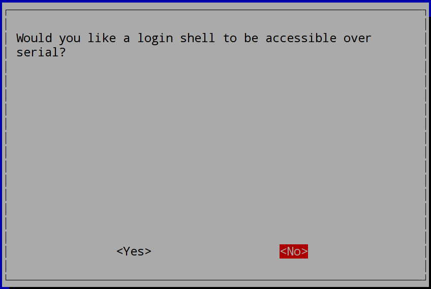
Click NO for would you like the login shell to be accessible over serial. This feature allows you to SSH into the Pi with a console cable from a computer using GPIO pins 14 and 15. It needs to be disabled so it doesn’t interfere.
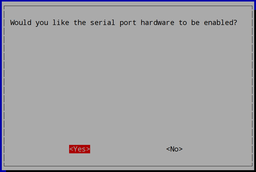
Then click YES for would you like the serial port hardware to be enabled. Click OK, Finish to exit and Yes to reboot.
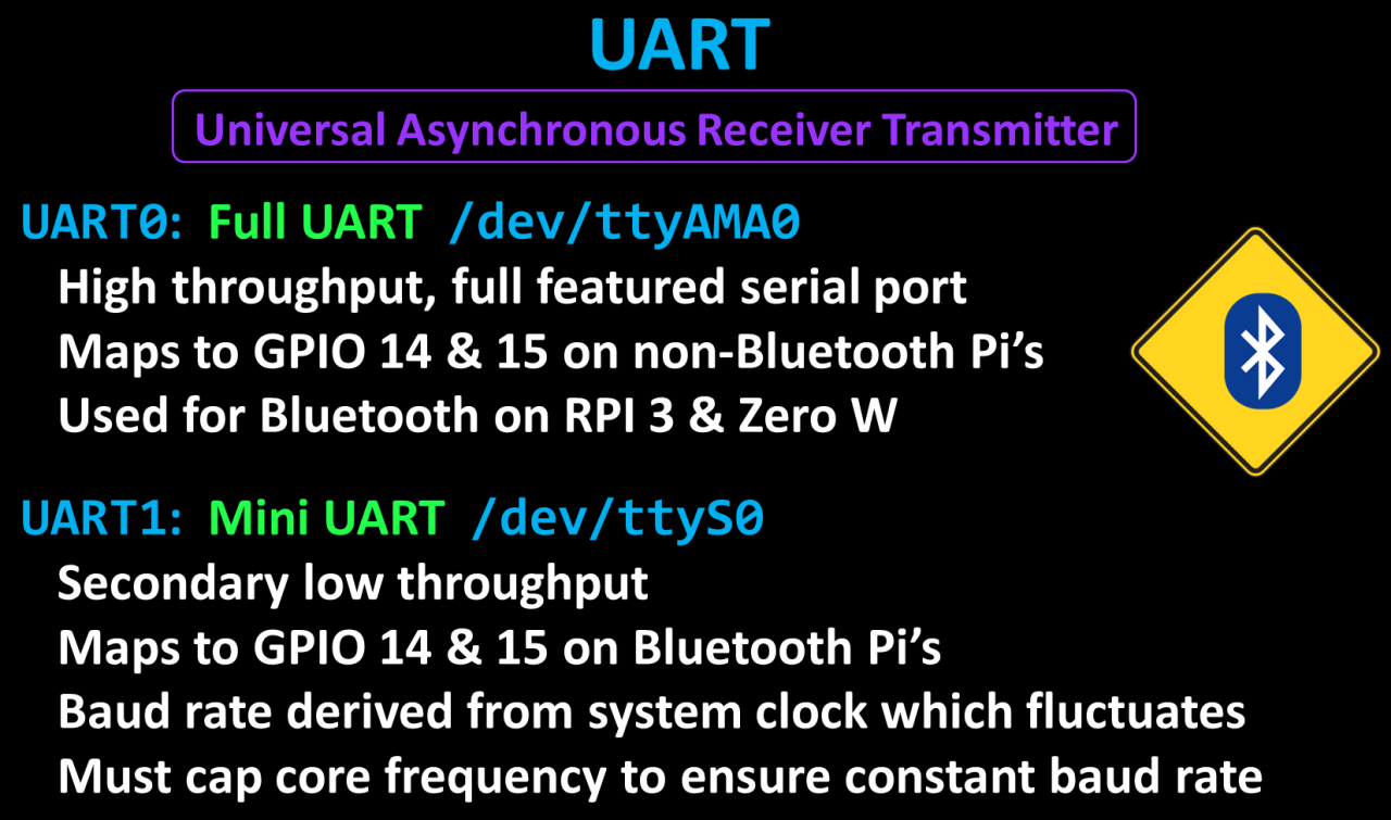
Please note that enabling the serial port could have performance issues on a Raspberry Pi with Bluetooth such as the Pi 3. The Pi has 2 UART ports which stands for universal asynchronous receiver transmitter. The first is UART0 on port TTYAMA0. It’s a high throughput, full featured serial port. It’s mapped to GPIO pins 14 and 15 on non-Bluetooth Pi’s. However, on the Raspberry PI 3 and Zero W it is appropriated for Bluetooth. The 2nd, UART1 on port TTYS0 is called the Mini UART. It’s only for low throughput applications, and on Pi’s with Bluetooth, it’s mapped to GPIO 14 & 15. One downside of the Mini UART, is that the baud rate is derived from the system clock. In order to ensure a constant baud rate it’s necessary to cap the core frequency to the lowest constant minimum frequency. Therefore, on the Pi3 the core frequency is capped at 250 MHz. This can lower the Pi’s performance and you’re still stuck with a low throughput port. Again this only applies to Pi’s with built in Bluetooth. So for serial applications you might be better off using an older Raspberry Pi.
The only other option that I’m aware of on Bluetooth Pi’s is to disable the Bluetooth and remap the header pins to use the full UART. This feature is called a pin-crossbar. To disable on-board Pi3 Bluetooth and restore UART0/ttyAMA0 over GPIOs 14 & 15 add the following line at the end of /boot/config.txt:
dtoverlay=pi3-disable-bt
On a Pi4 you would use:
dtoverlay=disable-bt
Also use the following command to stop the BT modem from trying to use the UART:
sudo systemctl disable hciuart
The python XXV Tracer library will handle all communication with the charge controller. It is designed for the SainSonic 1215RN but it works fine with my EP Solar 1210RN. On the Pi, in a terminal type CD tilde to ensure you’re in the home directory. Then use git clone to download the library:
git clone https://github.com/xxv/tracer.git
There’s no need to install anything. The python library can be imported directly from this folder using sys.path.append.
A light weight python web framework called Flask will be used to create a REST API, which is a very simple web server that can be used to receive or send data to a program, a mobile app, a web page or any device with web access. Flask comes pre-installed with the latest version of Raspbian.
The python code follows. A port is created for serial port TTYAMA0. Baud rate is 9600 and a 1 second read time out. A tracer is instantiated with hex ID 16. This appears to be the default ID. A tracer serial is instantiated and passed the tracer and the serial port. A query command is instantiated to poll the controller.
A flask app is instantiated. @app.route is a decorator that is placed before a function. It tells the program that when someone browses to that web path, it should trigger the function. Solar is specified for the route. Get is set for the method which indicates this route only answers to GET requests and not to Posts Puts, Deletes, etc . Get data when fired will query the charge controller and receive the data. The data is returned using jsonify to convert it to json format. Battery voltage, panel voltage, charging current and load current are returned in response to web requests to the solar route.
A 503 error code is also returned if an error occurs to let the web browser or app know that something went wrong. App.run() is called which will start the Rest API.
from flask import Flask, jsonify
from time import sleep
from serial import Serial

import sys
sys.path.append('/home/pi/tracer/python')
from tracer import Tracer, TracerSerial, QueryCommand

port = Serial('/dev/ttyAMA0', 9600, timeout=1)
port.flushInput()
port.flushOutput()
tracer = Tracer(0x16)
t_ser = TracerSerial(tracer, port)
query = QueryCommand()


# Rest API
app = Flask(__name__)

@app.route('/solar', methods=['GET'])
def get_data():
    try:
        t_ser.send_command(query)
        data = t_ser.receive_result()

        return jsonify(batt_voltage=data.batt_voltage,
                       pv_voltage=data.pv_voltage,
                       charge_current=data.charge_current,
                       load_amps=data.load_amps)

    except (IndexError, IOError) as e:
        port.flushInput()
        port.flushOutput()
        return jsonify({'error': e.message}), 503

try:
    app.run()

except KeyboardInterrupt:
    print ("\nCtrl-C pressed.  Closing serial port and exiting...")
finally:
    port.close()
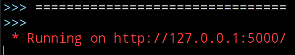
Run the python program and the shell should display the IP and port of the REST API.
Once running, the REST API can be testing using curl. The option -i is used to include the HTTP header. The local IP address is specified with port 5000 and the route is solar.
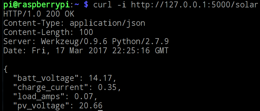
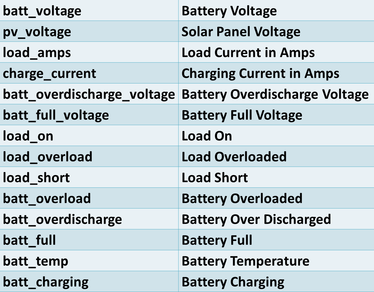
200 indicates that everything is OK. The content type is JSON. The response includes the photo-voltaic data. In addition to the 4 displayed values there are an additional 10 data variables available:
Currently, the web server is only running locally on the Pi on port 5000. If you just want to provide access on your home network you can pass the host parameter to Flask app.run. For example, the following will allow computers on your home network to make requests against the web server.
app.run(host='0.0.0.0')
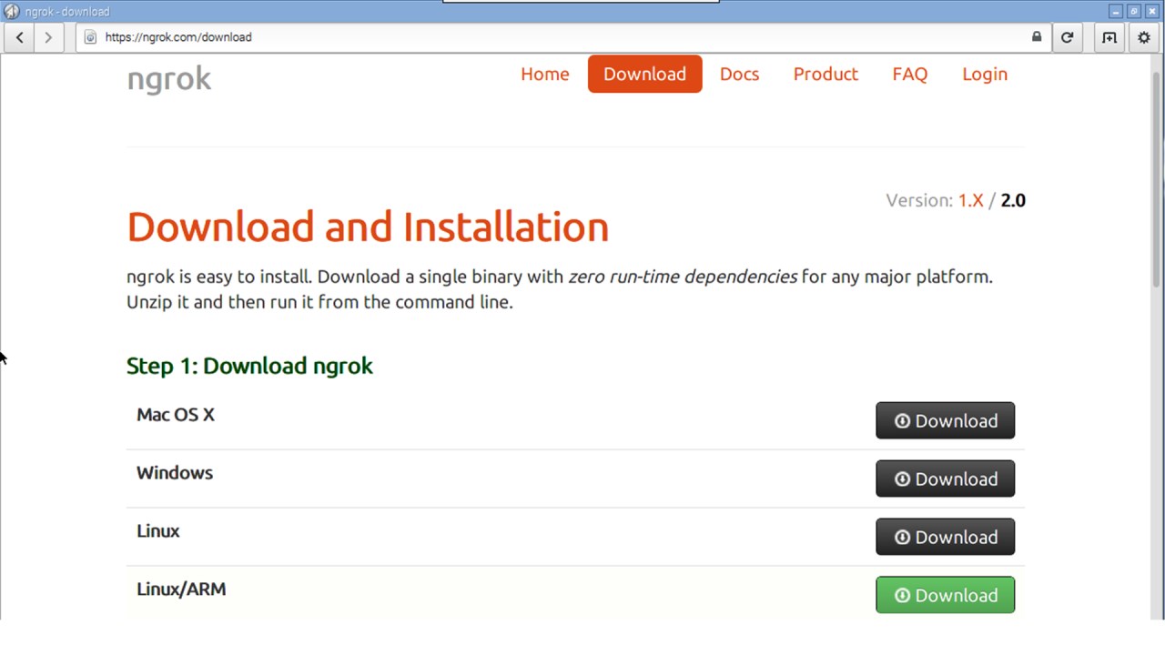
A free service called Ngrok can be used to host the web server on the public Internet. Browse to ngrok.com and sign up for an account. Afterwards, go to the download page and download the Linux/Arm version.
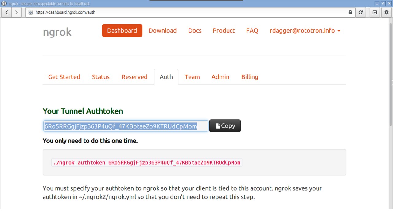
Go to the dashboard auth page and copy the Tunnel AuthToken to the clipboard. This will provide HTTPS secure communication.
Open a terminal and create a directory called ngrok. CD into the new folder and unzip the Ngrok download. Run Ngrok with the authtoken switch using the token you just copied to the clipboard. This only has to be done once. Use the http switch to start the Ngrok service on port 5000.
cd ~
mkdir ngrok
cd ngrok
unzip ~/Downloads/ngrok-stable-linux-arm.zip
./ngrok authtoken <Ngrok AuthToken>
./ngrok http 5000
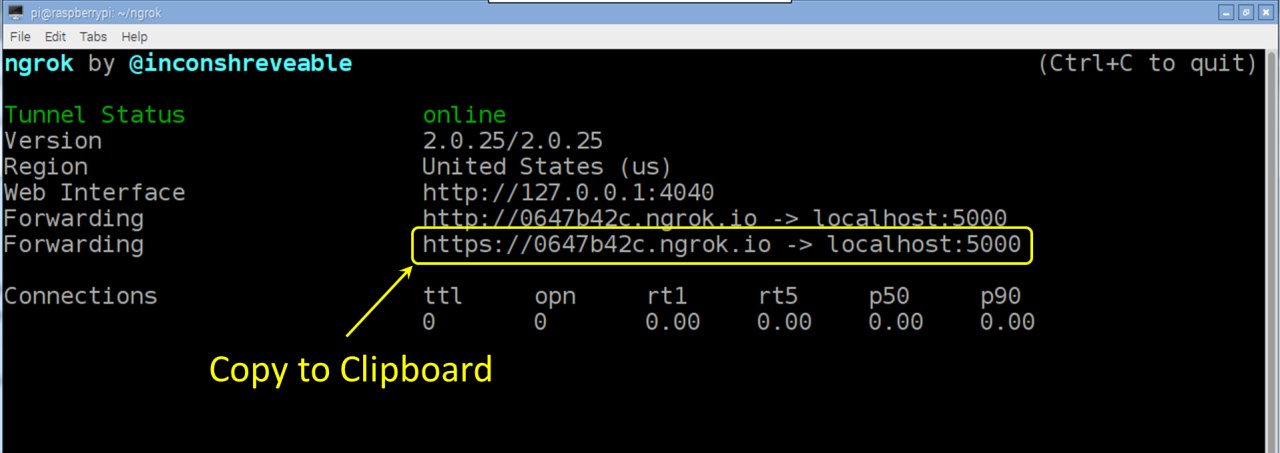
The status screen indicates your Pi is now on the Internet. Copy the https forwarding address to the clipboard. This is your Pi’s public web address. You can now access the solar data from any web enabled device at https://0647b42c.ngrok.io/solar
 Before putting your Pi on the public Internet, it is a good idea to make sure it is secure which is beyond the scope of this tutorial, but at the very least make sure you change the default password to a tough password, disable any unused services, throttle login attempts, use public-key or two-factor authentication and regularly update and back up your Pi.
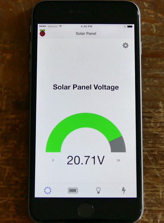
Here’s a simple React Native app for both Android and IOS that I created using Expo. Here it’s running on an iPhone. The tabs on the bottom switch between panel, battery, load and charge.
React is an open source JavaScript library created by Facebook to build interactive user interfaces. Facebook also provides React Native which lets you build mobile apps that run on both Android and IOS using JavaScript. Another brilliant tool that I used to create the app is Expo. It takes most of the complexity out of building mobile apps. With a few clicks you can start coding immediately and see the results on your phone too. Teaching React Native and Expo is beyond the scope of this tutorial. Instead I’m just going to demonstrate the JavaScript code that retrieves the charge controller data from the REST API.
The _fetchData method has a MobX action decorator to indicate that this method can change the state of the application. That just means that it can change variables that may require the UI to update. The JavaScript fetch command is passed the URL address of the REST API. The method is set to Get to indicate this is a GET Request. The returned response is a promise. If the response is OK; the json method is used to parse the data. Afterwards, the converted data is stored in the class’s observable data variable which automatically updates the screens if necessary. There is some error checking and then a timer is used call fetch again at a specified interval.
  @action _fetchData() {
    if (!this.address) {
      this.error = "No REST API address specified.\nPlease click settings.";
      return;
    } else {
      this.error = null;
    }
    // Fetch data from Rest API
    fetch(this.address, {
      method: 'GET',
    }).then((response) => {
      if (response.ok) {
        response.json().then((data) => {
          this.data = data;
          this.error = null;
        });
      } else {
        // Error
        response.json().then((r) => {
          this.error = r.error;
        });
      }
      // Repeat fetch at specified interval
      this.fetchTimer();
    }).catch((error) => {
      // Error no response
      this.error = error.message;
      // Repeat fetch at specified interval
      this.fetchTimer();
    });
  }
The full code for the app is available on my GitHub site.