
This is my 3rd tutorial on using LCD displays with the Raspberry Pi. I recommend you check out the first tutorial because this one builds on the former. The video demonstrates how to use I²C (pronounced I squared C) to control LCD Displays with PCF8574 and MCP23008 chips in Python:
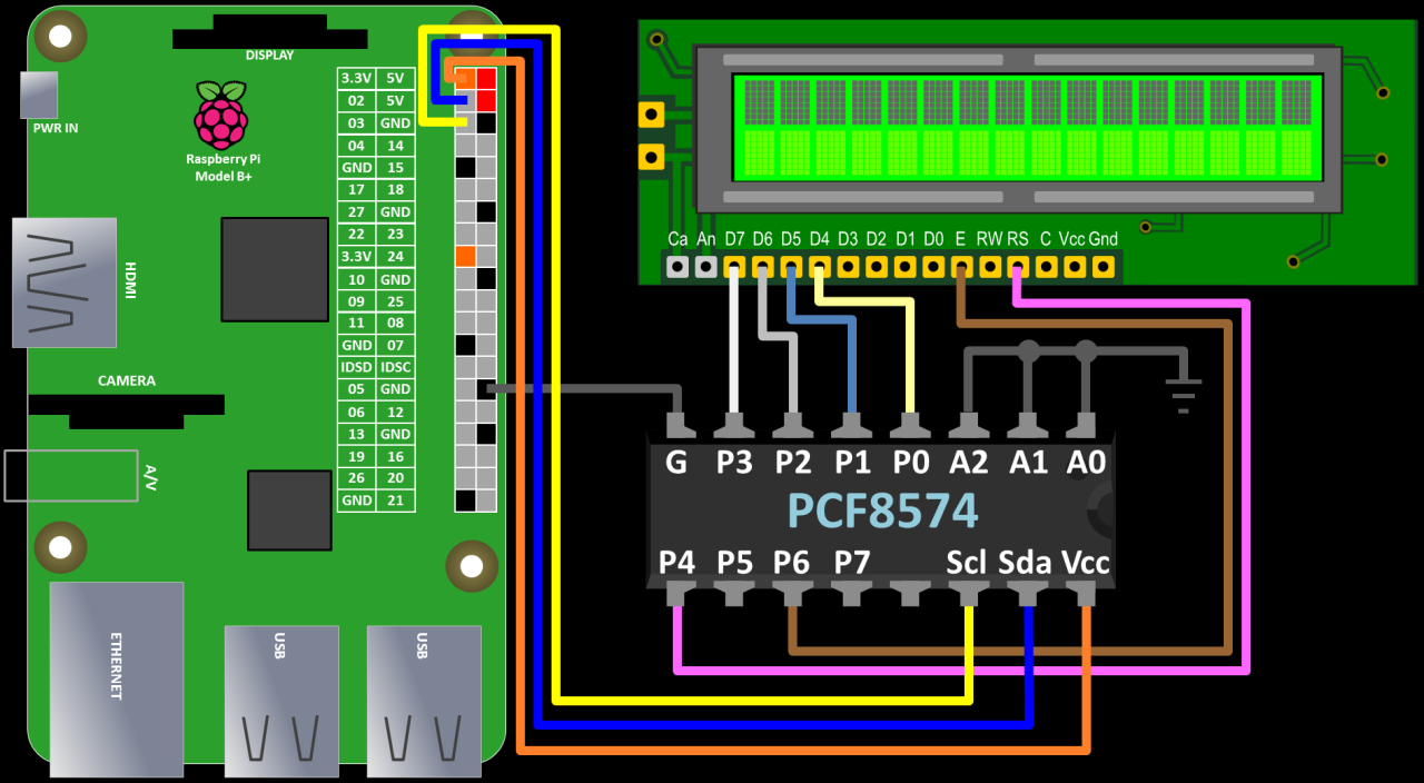
The PCF8574 wiring is very straight forward. A0 – A2 are used to specify an I²C address. Each I²C device requires a unique address. Grounding all 3 pins equates to hex address 20. P0 – P7 are basically 8 additional GPIO pins that you can control from the Pi. In this demo, 6 of these pins are used to control the LCD display in 4 bit mode. You can use any 6 pins in any order to control RS, Enable and the 4 data lines. SDA and SCL are the serial data and serial clock lines. The wiring in the video may be a bit confusing so just to be clear: SCL and SDA on the PCF8574 are connected to GPIO2 and GPIO3 on the Pi respectively. VCC on the PCF8574 is connected to one of the Pi’s 3.3 V pins and the chip’s ground is connected to one of the Pi’s grounds. I redrew the wiring to make the pinout easier to read:
 The diagram above only shows the PCF8574 specific connections. You still need to hook up the LCD power, contrast and back light. See first tutorial for details.
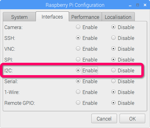
The latest version of Raspbian now makes it much easier to set up I²C. The only software requirements is to enable the I²C interface. From the Pi’s menu click Preferences – Raspberry Pi Configuration . Click the Interfaces tab and enable the I²C interface:
You can use the i2cdetect utility to check if everything is hooked up correctly. The last parameter 1 may need to be changed to 0 on earlier revision Pi’s. The chart below shows one I²C device connected at hex address 20:
pi@raspberrypi ~ $ sudo i2cdetect -y 1
     0  1  2  3  4  5  6  7  8  9  a  b  c  d  e  f
00:          -- -- -- -- -- -- -- -- -- -- -- -- --
10: -- -- -- -- -- -- -- -- -- -- -- -- -- -- -- --
20: 20 -- -- -- -- -- -- -- -- -- -- -- -- -- -- --
30: -- -- -- -- -- -- -- -- -- -- -- -- -- -- -- --
40: -- -- -- -- -- -- -- -- -- -- -- -- -- -- -- --
50: -- -- -- -- -- -- -- -- -- -- -- -- -- -- -- --
60: -- -- -- -- -- -- -- -- -- -- -- -- -- -- -- --
70: -- -- -- -- -- -- -- --
 Please note that Adafruit has made breaking changes to their libraries since the video. The following codes has been updated to reflect those changes.
The sample code from the video uses the Adafruit CharLCD library. It is now easier to install with pip:
sudo pip install adafruit-charlcd
It’s no longer necessary to create a PCF8574 class, because Adafruit has added a PCF8574 class to their python GPIO library which is automatically installed when you install the above CharLCD library.
Unlike the video, the code imports the Adafruit GPIO PCF8574 class which is passed the hex address 20 when instantiated. All you have to do is pass this GPIO as the optional GPIO parameter when you declare the Adafruit_CharLCD object. Then you can use the LCD display as if it were directly connected to the Pi’s GPIO.
from Adafruit_CharLCD import Adafruit_CharLCD
import Adafruit_GPIO.PCF8574 as PCF

GPIO = PCF.PCF8574(address=0x20)

# Define PCF pins connected to the LCD.
lcd_rs        = 4
lcd_en        = 6
d4,d5,d6,d7   = 0,1,2,3
cols,lines    = 16,2

# Instantiate LCD Display
lcd = Adafruit_CharLCD(lcd_rs, lcd_en, d4, d5, d6, d7,
                       cols, lines, gpio=GPIO)
lcd.clear()

lcd.message('  Raspberry Pi\n  I2C LCD 0x20')
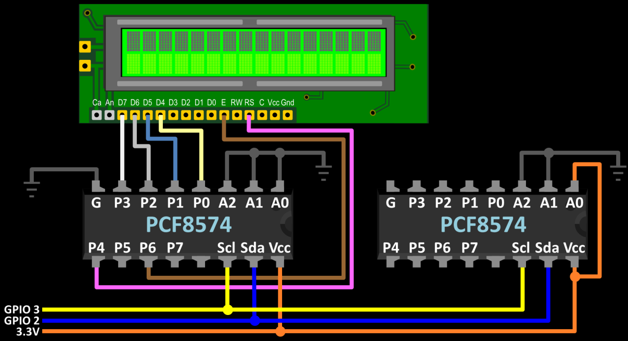
The great thing about I²C is that you can daisy chain multiple devices while only using 2 Pi GPIO pins. Just extend SDA and SCL to the additional devices and provide power and ground. Each device must have a unique I²C address. In the wiring diagram below, I add a 2nd PCF8574 and change A0 to high which changes the hex address from 20 to 21.
Here is sample code to control 2 LCD displays. A 2nd GPIO2 is declared for the device at hex address 21. A 2nd LCD is declared with GPIO2 passed for the GPIO parameter. Now 2 displays can controlled from Python:
from Adafruit_CharLCD import Adafruit_CharLCD
import Adafruit_GPIO.PCF8574 as PCF

GPIO = PCF.PCF8574(address=0x20)
GPIO2 = PCF.PCF8574(address=0x21)

# Define PCF pins connected to the LCD.
lcd_rs        = 4
lcd_en        = 6
d4,d5,d6,d7   = 0,1,2,3
cols,lines    = 16,2

# Instantiate LCD Display
lcd = Adafruit_CharLCD(lcd_rs, lcd_en, d4, d5, d6, d7,
                       cols, lines, gpio=GPIO)
lcd.clear()

lcd2 = Adafruit_CharLCD(lcd_rs, lcd_en, d4, d5, d6, d7,
                        cols, lines, gpio=GPIO2)
lcd2.clear()

lcd.message('  Raspberry Pi\n  I2C LCD 0x20')
lcd2.message('  LCD Display #2\n  I2C LCD 0x21')
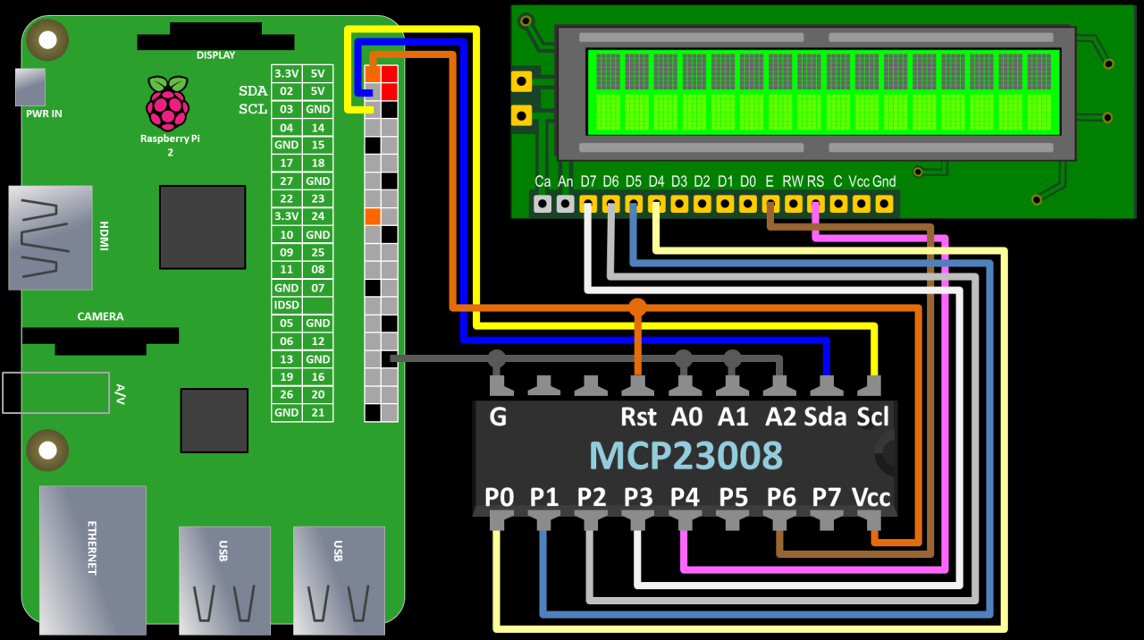
The MCP23008 is another I²C expander chip that is commonly used to control LCD displays. The wiring is similar to the PCF8574. You just need to make sure that the Reset pin is pulled high by connecting it to 3.3 V. Please note that the schematic in the video had an error. Here is the corrected version:
The Adafruit Char_LCD library has built-in support for the MCP23008 so the Python code is even easier. Import the Adafruit_MCP230xx class and use it to declare a GPIO. The rest of the code remains the same as for the PCF8574.
from Adafruit_CharLCD import Adafruit_CharLCD
import Adafruit_GPIO.MCP230xx as MCP

GPIO = MCP.MCP23008(address=0x20, busnum=1)

# Define PCF pins connected to the LCD.
lcd_rs        = 4
lcd_en        = 6
d4,d5,d6,d7   = 0,1,2,3
cols,lines    = 16,2

# Instantiate LCD Display
lcd = Adafruit_CharLCD(lcd_rs, lcd_en, d4, d5, d6, d7,
                       cols, lines, gpio=GPIO)
lcd.clear()
lcd.message('  Raspberry Pi\nI2C LCD MCP23008')
1 Trackback