
This is a perfect example of why it takes me so long to get projects done. I was working on my computer controlled vacuum chamber to create better lens for my RGB Volcano Buttons which behooved me to create a 24V step up circuit which required an inductor. Looking though my parts bin I found many inductors but had no way to determine their values. Hence my Inductance Meter. I selected a Wintergreen Altoids tin as my project enclosure.
Below is the 3D model of the circuit board created in POV-Ray using Eagle3D. The meter is controlled by an Atmel AVR microcontroller.
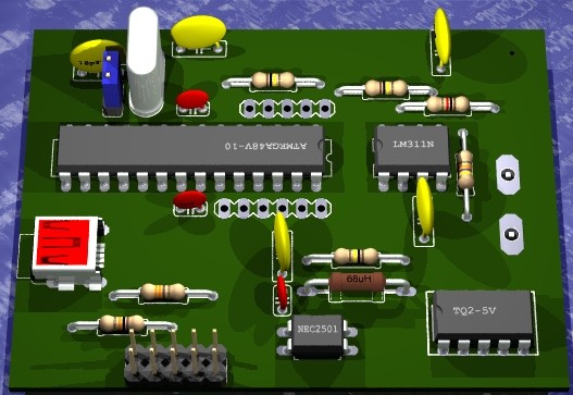
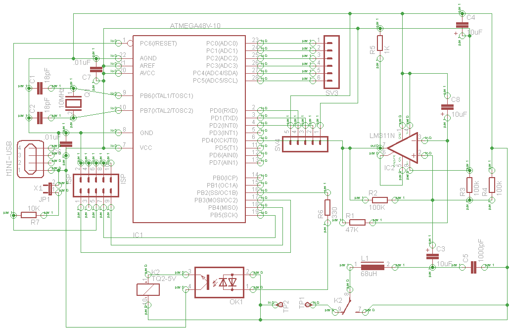
I designed the schematics and circuit board using the free version of CadSoft Eagle.
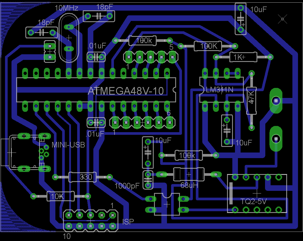
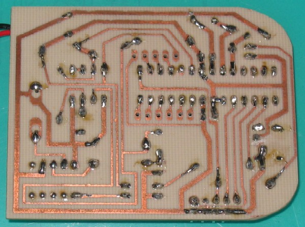
I designed the board to be single-sided and no bridges are required.
I etched the circuit board using a laser printer, glossy photo paper, hydrogen peroxide and muriatic acid. Here are my etching notes.
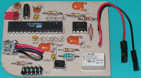
Here is the completed board. The 11 unconnected pads are for the LCD display and 3 pushbuttons which are mounted to the lid of the case. The red and black plugs connect to banana jacks on the side of the case.
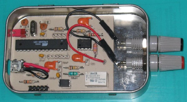
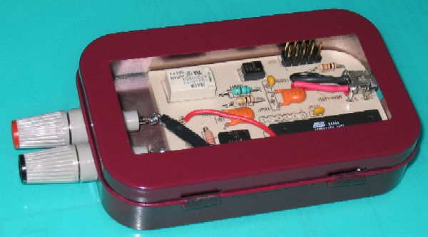
Here is a shot of the board mounted in the case. The Altoids tin is not very deep so I had to make the board as low profile as possible. Therefore, none of the IC’s are in sockets. I used an extra small crystal and I found a very flat DPDT 5V relay on an old modem card which also provided the opto-coupler that allows the AVR to drive the relay. I bent the larger capacitors down and I selected a mini-USB connector to supply the 5V power. I have a box in my office of broken PDA’s and cell phones that people have given me over the years. A smashed Blackberry provided the USB connector. The SMD mini-USB proved very difficult. I soldered 3 posts to the connector to mount it securely to the board. However, when I tried bending the surface mount pins, they immediately broke off. Much to my amazement, I was able to solder leads to the tiny +5V and ground stubs. With minor modifications the meter could also be used to measure capacitance, but the extra parts would have made it harder to fit in the Altoids tin and I already have a multi-meter that measures capacitors.
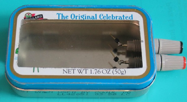
Next I cut a rectangular opening in the Altoids top. This was not easy because the opening had to be very precise to hold the LCD display. First I tried a nibbler, but the tin kept jamming the blade. I also tried a scissor, which cut well but was too hard to navigate in the confined space. Then I tried my Dremel with a carbide disc. This cut very well, but I ruined 2 tins because I couldn’t cut straight enough. Fortunately, a co-worker eats a lot of Altoids. The third was a success after I built a small jig out of some old 3.5″ hard drive mounts to keep the Dremel blade straight.
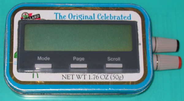
I salvaged the LCD display from a box of broken business phones at my office. The display fits perfectly in the opening. There are also 3 buttons built in to the display. The mode button initiates a calibration. I’m using the page and scroll buttons to lock and unlock the display. The LCD plastic cover, buttons and the LCD display are held in place by friction. It is very tight fit inside the case and when the cover is closed nothing moves around.
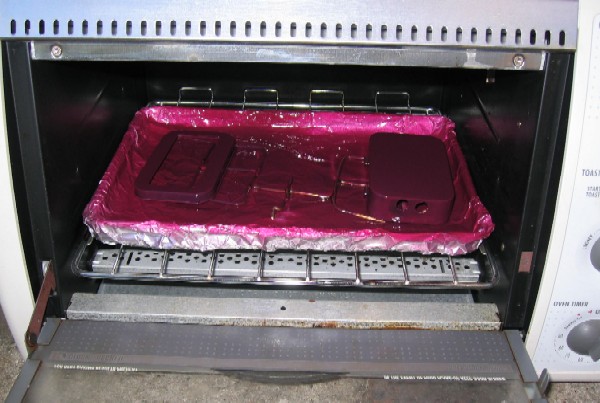
I picked up a used Redline powder coating gun on eBay that I was anxious to try out. I soldered together a rig of 12 gauge copper wire to hold and ground the pieces of the Altoids case while coating. It worked well but I didn’t consider something very important…
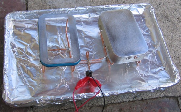
I neglected the fact that solder melts at about the same temperature that powder coating melts. While cooking the powder in my toaster oven at 375F the rig collapsed. Still the damage was not too bad. I lost some of the powder on the sides, but it made an interesting pattern and the flaking was only along the rim which you can’t see when closed.
The reassembled case after powder coating.
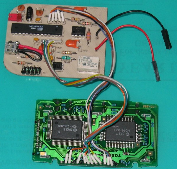
The LCD display connected to the main circuit board. The pinout of the LCD controller is a little different from most HD44780’s. There are no DB0-DB3 connections. Instead the 15 pin connector on the display contains 3 pins and a dedicated ground for the 3 pushbuttons.
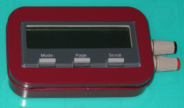
The LCD display mounted. The photo doesn’t really do the powder coating justice. The color is a very rich burgundy.
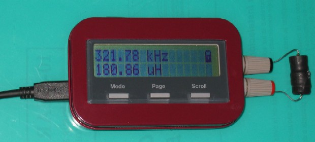
The meter measuring a 180μH inductor. The lock in the upper right corner indicates that the display has been locked.
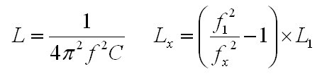
I wrote the software for the AVR chip using Bascom-AVR from MCS Electronics. Using the formulas below, the code solves for inductance (L) using 2 known values: capacitance (C) and frequency (f). The capacitance is set using a 1nF capacitor and the frequency is generated using the comparator. Once the meter is calibrated then the second formula can be used to determine the change in inductance when an inductor is placed across the probes.
The above design was adapted from several similar projects on the web:
AVR LC Meter (in Dutch but includes many great links)
Very Accurate LC Meter based on PIC16F84A IC.
Downloads:
Version 0.10 – Released 08/20/2006 – For ATMEGA48V (Requires fuses set to 10 MHz external crystal with no divider, CKSEL=1110 and SUT=00)
Source code and compiled hex.
Eagle files.
The total cost of the project is about $15.
Parts List:
| Description | Qty |
|---|---|
| Atmel ATMEGA48V-10PI | 1 |
| 10 MHz Crystal HC49/US | 1 |
| Resistor Carbon Film 330 Ohm 1/4 Watt 10% | 1 |
| Resistor Carbon Film 1K Ohm 1/4 Watt 10% | 1 |
| Resistor Carbon Film 10K Ohm 1/4 Watt 10% | 1 |
| Resistor Carbon Film 47K Ohm 1/4 Watt 10% | 1 |
| Resistor Carbon Film 100K Ohm 1/4 Watt 10% | 3 |
| Ceramic Radial Capacitor 18pF 50V 5% | 2 |
| Ceramic Radial Capacitor 1nF 50V 5% | 1 |
| Ceramic Radial Capacitor .01μF 50V 10% | 2 |
| Dipped Solid Aluminum Capacitor 10μF 16V 20% | 3 |
| 68μH Axial Inductor | 1 |
| 2 Pin Right Angle Header .100" | 1 |
| Shunt .100" | 1 |
| 5 x 2 Pin Gold Straight Header .100" | 1 |
| LM311N Comparator 8 DIP | 1 |
| NEC 2501 Opto-Coupler | 1 |
| NAIS TQ2SA 5V DPDT Relay 10 DIP | 1 |
| Mini-USB SMD Connector | 1 |
| Banana Jacks | 2 |
| LCD Display 16×2 with HD44780 Controller & 3 pushbuttons | 1 |
| Single-sided Copper Clad Board 1 oz. 2.75" x 2.125" | 1 |
| Altoids 50g Tin | 1 |