
In this project I build several OLED displays that can be controlled by mobile phones. We have a guest Wi-Fi system in our office that handles a large number of daily visitors. I noticed leaflets with the Wi-Fi password scattered throughout the office. This just felt like bad security, so I decided to come up with a better approach. The goal is to have an electronic display in every conference room that can clearly display the Wi-Fi SSID, password and a Wi-Fi QR code. The display will also allow employees to send custom notifications. In previous videos I’ve written phone apps or used existing apps to control my projects, but in this case, we’ll keep it simple by using SMS text messaging for control and feedback.
Table of Contents
- Adafruit IO
- Twilio
- MQTT Manager
- OLED Display
- Disconnection Layer
- Clock Layer
- Message Layer & I2S Amp
- Password Layer
- Main Program
- Environment Variables
- The Build
- Downloads
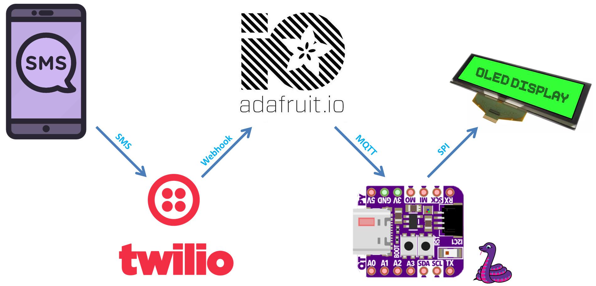
Communication flows from a mobile phone via SMS text message to a Twilio API function which then fires a webhook on the Adafruit IO cloud service. A CircuitPython program running on an ESP32-S2 Wi-Fi enabled board monitors the Adafruit IO feed using MQTT and then performs commands or displays any published messages on an OLED display.
Adafruit IO
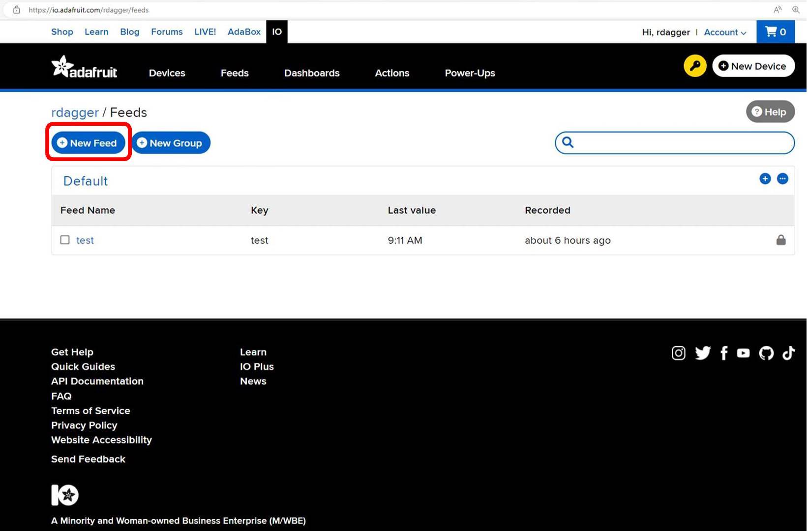
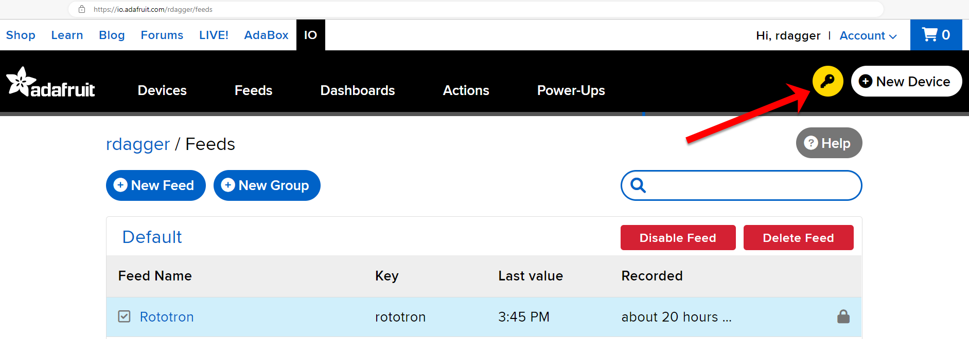
Adafruit IO is a paid service, but they do offer a free plan which I’m currently using. Leveraging Adafruit IO saves me the trouble of spinning up and maintaining a web server and an MQTT broker. The setup is unbelievably easy. You just navigate to the Feeds tab and then click New Feed. Then give it a name and click create.
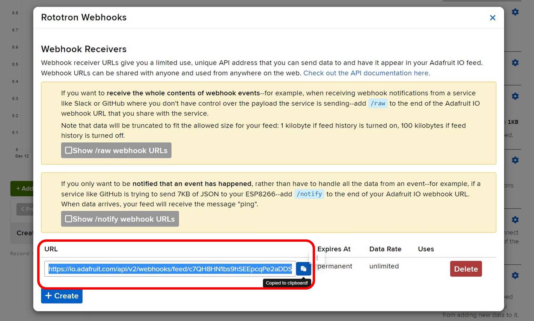
Next click the gear icon next to Webhooks and click Create. This generates a webhook URL which you’ll need for Twilio. Copy the URL to the clipboard.
Twilio
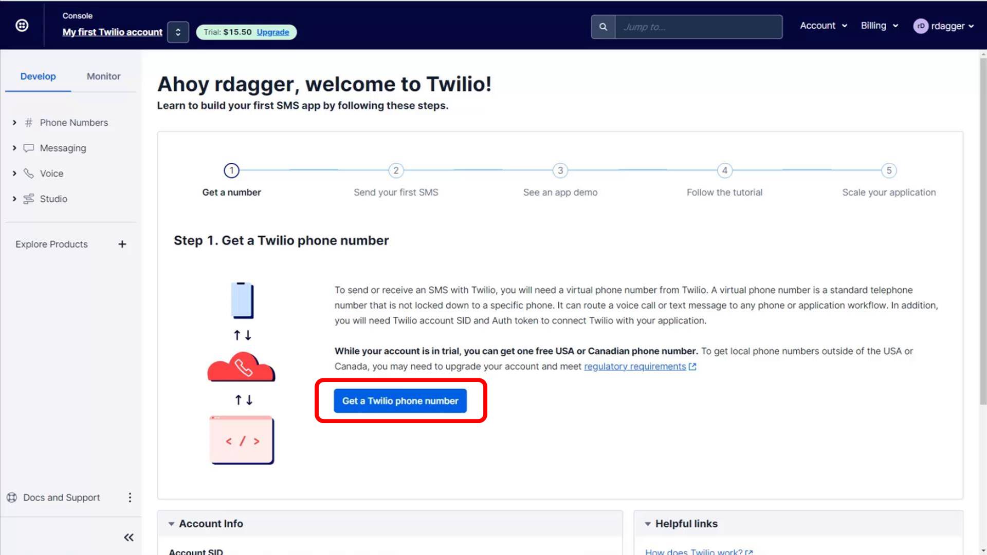
Twilio is a paid service, but they offer a free trial that gives you a small credit. We are currently paying $1.15 US per month for a local phone number and around a penny per text (send or receive) which includes a carrier fee and taxes. Still YMMV depending on your country and carrier. The trial account does not require a credit card. Twilio is a very robust system, but configuration was relatively easy because I’m only using a tiny subset of its functionality. After creating an account, you will need to click Get a Twilio phone number.
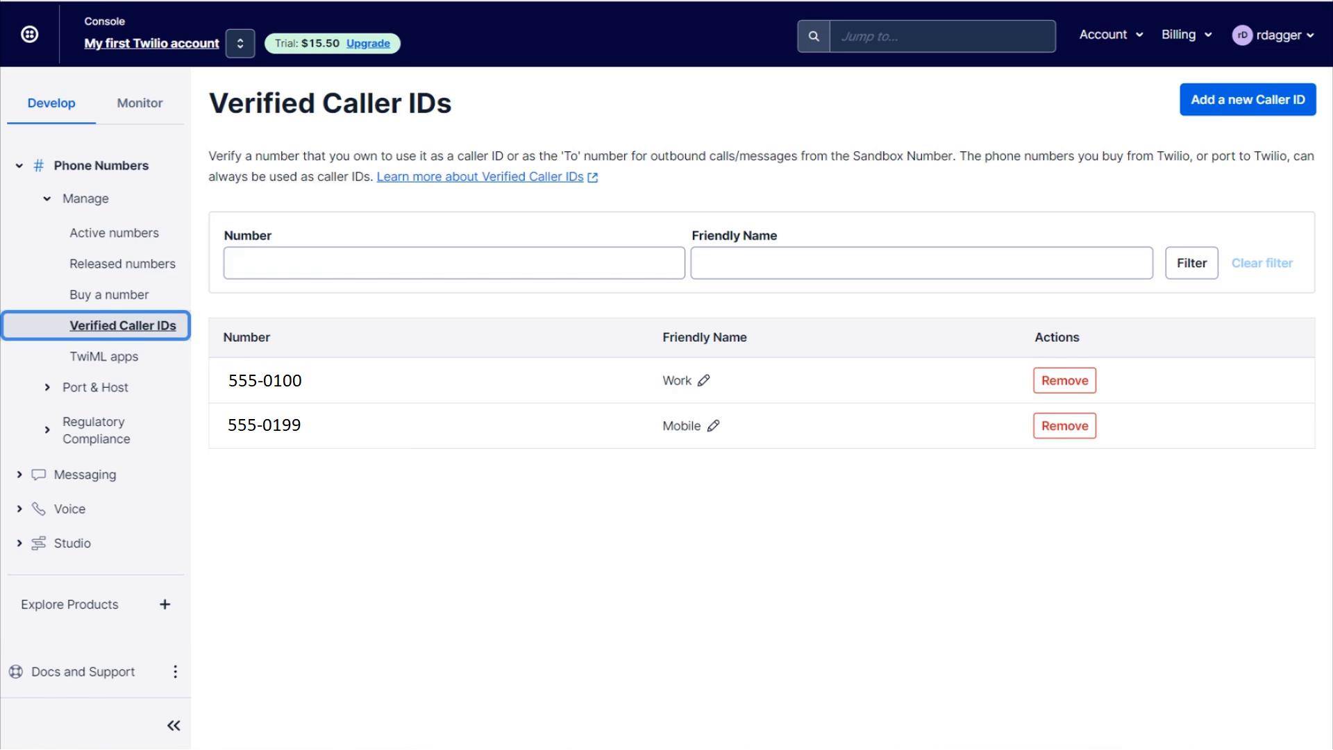
Next you need to verify all phone numbers that will be allowed to receive texts from your new number. It’s a constraint set by the low-cost plan but it’s alright because we only have a few users.
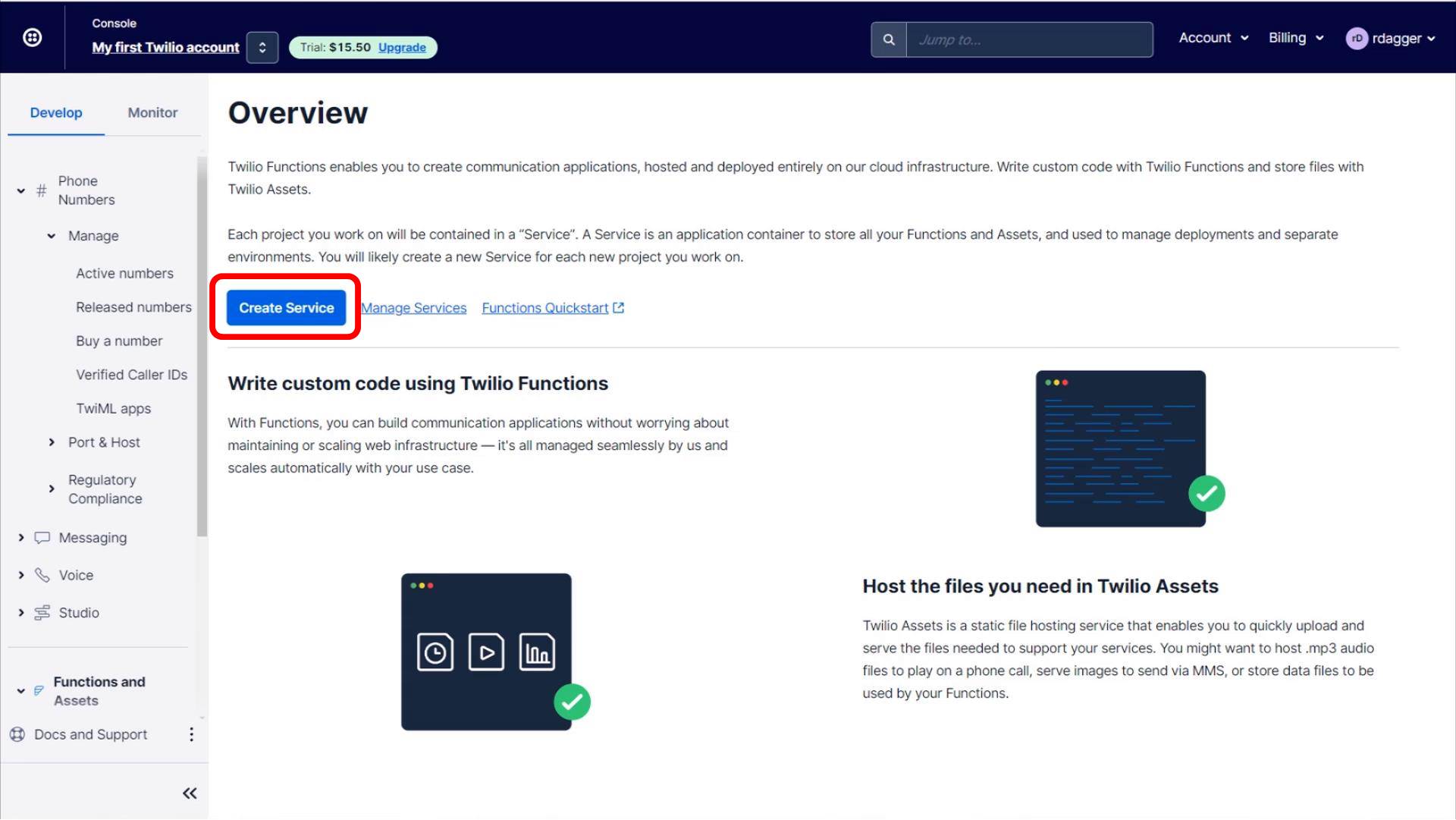
In theory, you could just add the Adafruit IO webhook address to your new Twilio phone number and the Adafruit IO feed would start receiving text messages. Unfortunately, this currently doesn’t work properly because Adafruit IO only supports JSON and Twilio expects XML. Hopefully, this will change in the future. However, it’s not too difficult to remedy by implementing a Twilio services with a single Node.js function to process the webhook. Locate the Functions and Assets tab. Please note you may need to click Explore Products and search under Developer tools. You can always click the 3 dots next to a tab to pin it to the side bar. Click Create Service and give it a name.
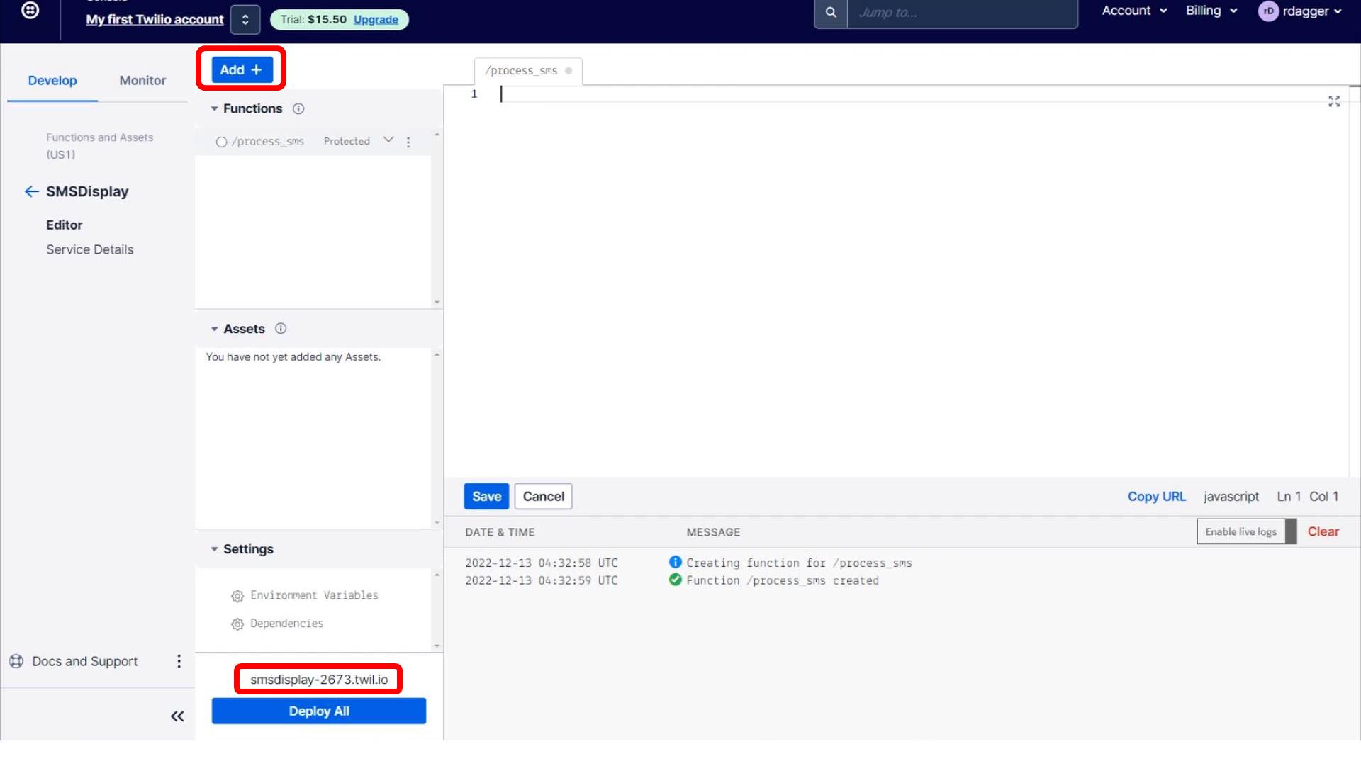
Click Add to create a new function and call it process_sms. Also please make a note of the address just above the Deploy All button. This is the function address which is combined with the function name. For example, the address below would be http://smsdisplay-2673.twil.io/process_sms.
This Axios HTTP client is required to post to Adafruit IO. Please make sure you add “axios” under Settings – Dependencies. The JavaScript code first adds the require statement for axios. Next the incoming text message length is checked, and a failure message is returned via SMS if it is too long. Otherwise, the message is posted to the Adafruit IO feed using the Adafruit Webhook URL that was generated above. A confirmation reply is returned to the sender unless an error occurs. Please note that the reply does count toward your bill as a second text message.
const axios = require('axios');  // Make sure you add axios to Settings - Dependencies
const MAX_SMS = 54  // Maximum SMS text message character length

exports.handler = async (context, event, callback) => {
  // Create a new message response object
  const twiml = new Twilio.twiml.MessagingResponse();

  // REST API base URL and any custom headers
  const instance = axios.create({
    baseURL: 'https://io.adafruit.com/api/v2/webhooks/feed/',
    headers: { 'X-Custom-Header': 'Twilio' },
  });

  try {
    // Validate message length
    if(event.Body.length > MAX_SMS){
      twiml.message(`Message too long by ${event.Body.length - MAX_SMS} characters!  (Maximum ${MAX_SMS})⛔`);
      return callback(null, twiml);
    }
    // ADAFRUIT WEBHOOK URL GOES HERE
    const update = await instance.post('/c7QH8HN1bs9hSEEpcqPe2aDDSRp9/', {
      value: event.Body
    }).catch(function (error) {
      // Catch post failure and notify sender
      twiml.message(`Something went wrong! ⛔`);
      return callback(null, twiml);
    });

    // Add a message to the response to let the user know that everything worked
    twiml.message(
      `Message received. ☘️`
    );
    return callback(null, twiml);
  } catch (error) {
    // As always with async functions, you need to be sure to handle errors
    console.error(error);
    return callback(error);
  }
};
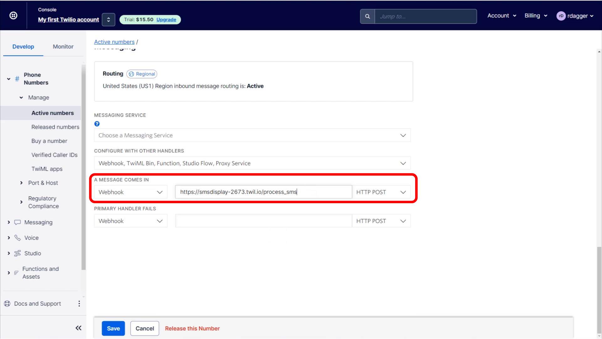
Save the code above and then click Deploy All. Navigate to Phone Numbers – Active numbers and click your Twilio phone number. Scroll down to the section titled “A MESSAGE COMES IN”. Type in the address to the process_sms function above and click Save
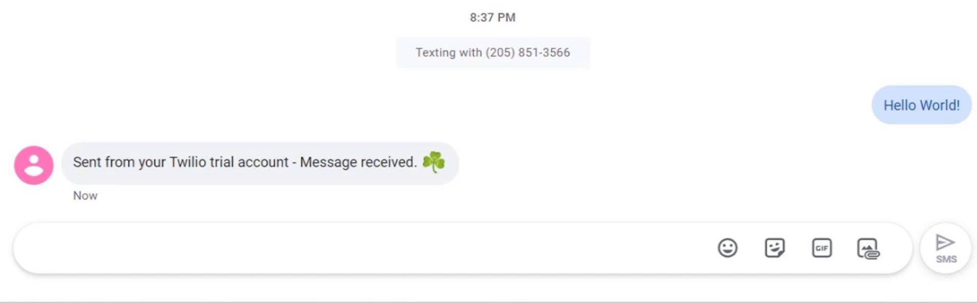
Now test the function by sending a text to the Twilio phone number. You should get a “Message received” reply. If you don’t make sure you verified the caller ID of the mobile phone you’re using. You can also check the Twilio logs for errors. The prepended “Sent from your Twilio trial account” will be removed after your first payment.
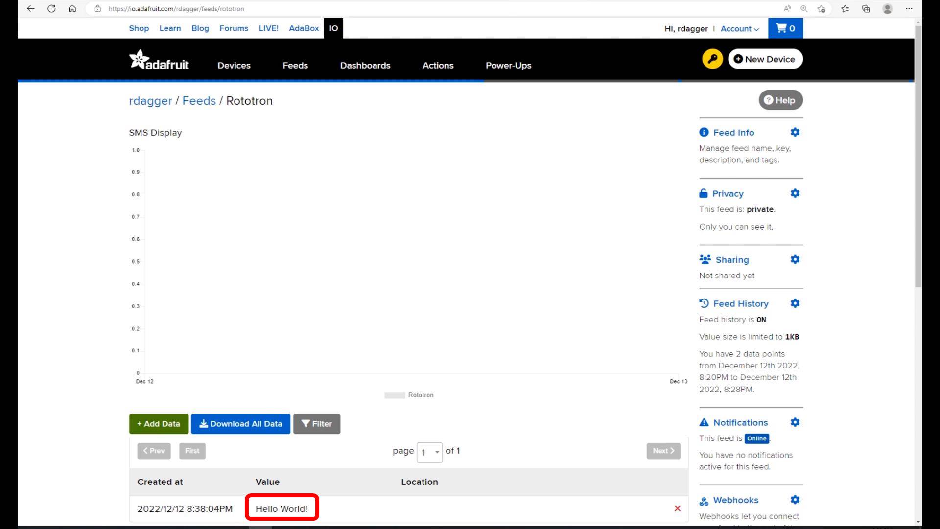
If everything worked, then your message should show up on the Adafruit IO feed.
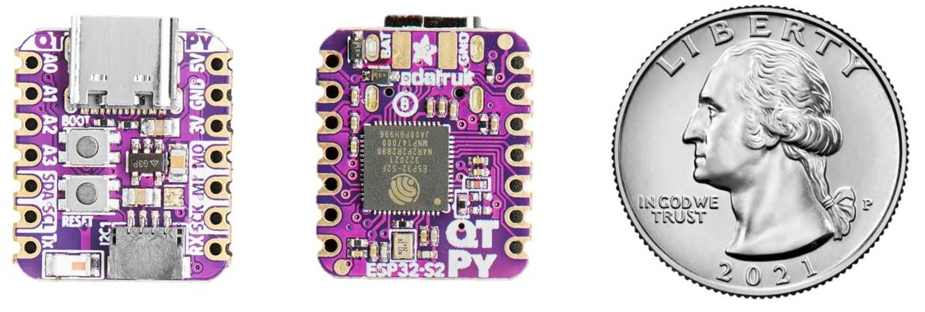
An Adafruit QT PY ESP32-S2 will be used to monitor the Adafruit feed over the web using MQTT. The QT PY is a low-cost, Wi-Fi enabled board with a single-core 240 MHz Tensilica chip. It has a real time clock and supports I2S audio, ADC, PWM, SPI, I2C and much more all in an extremely compact form factor.
MQTT Manager
The lower level MQTT is handled by the adafruit_minimqtt library, but I wrote a class called mqtt_manager to manage all the MQTT communication between the QT PY and Adafruit IO. The constructor for the MQTTManager class takes an mqtt_client and a callback function onmessage that will be triggered when an MQTT message is received. The Adafruit IO feed address is retrieved from the environment variable AIO_FEED. An instance variable status tracks the connection status and will initially be set to disconnected. Next 4 callback methods are wired to the MQTT client: on_connect, on_disconnect, on_message and on_subscribe.
import adafruit_minimqtt.adafruit_minimqtt as mqtt
from os import getenv

class MQTTManager:
    """Handle MQTT communications."""
    def __init__(self,
                 mqtt_client: mqtt.MQTT,
                 onmessage: callable):
        """Initialize.

        :param MQTT mqtt_client: MQTT Client
        :param callable onmessage: Callback for subscribed messages
        """
        self.mqtt_client = mqtt_client
        self.aio_feed = getenv("AIO_FEED")
        self.onmessage = onmessage
        self.status = "DISCONNECTED"  # Used to track MQTT connection status
        # Wire the callback methods
        self.mqtt_client.on_connect = self.connected
        self.mqtt_client.on_disconnect = self.disconnected
        self.mqtt_client.on_message = self.message
        self.mqtt_client.on_subscribe = self.subscribed
The connected callback is fired when the MQTT client makes a successful connection to Adafruit IO. The status variable is changed to connected and then the subscribe method is called to subscribe to the specified Adafruit IO feed with QOS=1. MQTT provides 3 QOS (quality of service) levels. Level zero is basically no guarantee of delivery (sort of like the post office). Level one ensures that your message will be delivered at least once. Level two ensure that your message is delivered exactly once. Level two is currently not supported by Adafruit IO. The disconnected callback fires when the MQTT client is disconnected. The status is set to disconnected. The message callback is fired when a message is received. It relays the message to the onmessage callback that was initially passed into the class. The subscribed callback is fired when the MQTT client successfully subscribes to a feed. Please note that there is currently a bug in the granted_qos level. If you set the MQTT client to QOS=2 then the granted_qos will also show 2 even though it’s not supported and not actually running.
    # Define callback methods for Adafruit IO MQTT feed
    def connected(self, client, userdata, flags, rc):
        """Fired when client successfully connected to broker."""
        self.status = "CONNECTED"
        print(f"Adafruit IO connected.  Client ID: {client.client_id}")
        # Subscribe to all changes on the feed.
        client.subscribe(self.aio_feed, qos=1)

    def disconnected(self, client, userdata, rc):
        """Fired when client is disconnected from broker."""
        self.status = "DISCONNECTED"
        print("Disconnected from Adafruit IO.")

    def message(self, client, topic, message):
        """Fired when topic has new message."""
        print(f'Topic: {topic}, message: {message}')
        self.onmessage(message)

    def subscribed(self, mqtt_client, userdata, topic, granted_qos):
        """Fired when the mqtt_client subscribes to a new feed."""
        print(f'Subscribed to {topic} at QOS level {granted_qos}')
A method called connect is used to connect the MQTT client to Adafruit IO. It will only run if the status is disconnected to ensure multiple connections are not attempted. The status is changed to connecting. The actual connect command is wrapped in a try statement because Wi-Fi and Internet connections are not always reliable. If the command is successful, then the connected callback above should fire. Otherwise, if an exception occurs then the status is set back to disconnected.
    # Connect the client to the MQTT broker.
    def connect(self) -> None:
        # Only attempt connection if disconnected
        if self.status == "DISCONNECTED":
            self.status = "CONNECTING"
            print("Connecting to Adafruit IO...")
            try:
                self.mqtt_client.connect()
            except Exception as mqtt_connect_err:
                self.status = "DISCONNECTED"
                print(f"MQTT connection error: {mqtt_connect_err}")
The loop method checks the MQTT broker for messages. If the status is still connecting, then the method exits and returns false. If the status is disconnected, then the status is set to connecting and a reconnect will be initiated. If an error occurs, then the status is set back to disconnected. Either way the method exits and returns false. Finally, mqtt_client.is_connected is called to double check the connection, and if true then the loop method is called which checks for messages. Please note that the method is_connected does not return false if you’re not connected. Instead, it throws an error. I ran into a lot MQTT and Adafruit IO reliability issues and that is the main reason I wrote this class in an attempt to make it more bulletproof. There are several possible errors that can manifest as either an MMQTTException or an OSError. For the MMQTTException the method just returns false because it is probably just a networking issue that will fix itself. However, the OSError usually indicates a more serious condition that requires a disconnection and reconnection to fix.
    def loop(self) -> bool:
        try:
            if self.status == "CONNECTING":
                # Exit because still connecting
                print('Connecting')
                return False

            if self.status == "DISCONNECTED":
                # Reconnect to MQTT broker if disconnected
                self.status = "CONNECTING"
                try:
                    print("Attempting to reconnect to MQTT broker")
                    self.mqtt_client.reconnect(resub_topics=False)
                except Exception as recon_err:
                    print(f"MQTT broker reconnect failure: {recon_err}")
                    self.status = "DISCONNECTED"
                return False

            # Check for MQTT client connection disruptions
            if self.mqtt_client.is_connected():  # Throws error on false
                self.mqtt_client.loop()  # Check subscription for message
                return True
        except mqtt.MMQTTException as mqtt_err:
            # MQTT Error
            print(f"MMQTTException: {mqtt_err}")
            return False
        except OSError as os_err:
            # OS Error (probably WLAN or TLS)
            print(f"OSError: {os_err}")
            # Disconnect MQTT to force Reconnect
            self.status = "DISCONNECTED"
            return False
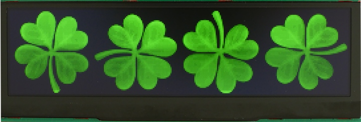
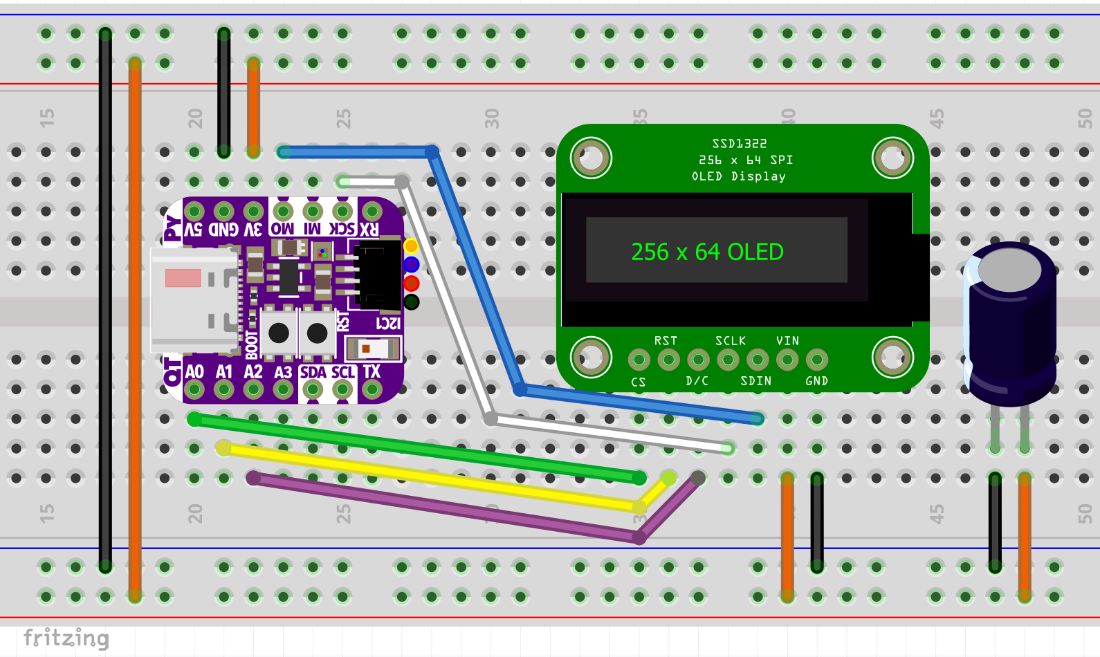
A large 5.5 inch (14 cm) green 256×64 OLED module will be used for the display. I bought it from a company called BuyDisplay and it is a model ER-OLEDM055. It’s an expensive display at $70 US, but you can get smaller 3.2 inch (8.1 cm) versions for a fraction of the price. The OLED display is very bright even in sunlit rooms and has a wide viewing angle. It can display 16 shades of green and is controlled by an SSD1322 IC. It supports 8-bit parallel and 3 or 4 wire SPI communication. It’s 3.3 V so it easy to hook up to the QT PY.
OLED Display
The OLED CS (chip select) line is connected to the QT PY’s A0. RST (reset) is connected to A1. DC (data/command) is connected to A2. It doesn’t really matter what pins are specified for CS, RST and DC because they will be specified in code. SCLK (serial clock) is connected the SCK. SDIN (serial data in) is connected to MOSI (master out slave in). Vin is connected to the QT PY’s 3.3 V line and the grounds are connected. The OLED can draw a lot of current which could brown out the QT PY. Therefore, a 100 μF capacitor is placed across the 3.3 V rail and ground.
In order to simplify the CircuitPython coding, I have broken the OLED display code into 4 separate classes:
- Clock Layer
- Disconnection Layer
- Message Layer
- Password Layer
The clock layer displays the time and date on the screen and also handle NTP synchronization with the ESP32’s real-time clock. The disconnection layer displays a warning icon if communication is lost. The message layer displays custom text messages. It also handles the I2S audio to play a notification chime. The password layer displays the Wi-Fi SSID and password. It also generates and displays a Wi-Fi QR code to facilitate guest access.
Disconnection Layer
The simplest code is the Disconnection Layer. The class takes a single parameter which is the primary Display IO group. The group can hold TileGrids which are used to display graphics, text and images. Adding or removing items from the group either displays them or hides them. A small 24×18 bitmap formatted to 4 bits-per-pixel is loaded from the flash storage using the OnDiskBitmap method. A new TileGrid is instantiated to hold the bitmap and is positioned in the lower right corner of the display. There is a single property called visible which defaults to false. The getter returns if the disconnected bitmap is currently visible, and the setter toggles the visibility by appending or removing the TileGrid from the Display IO group.
"""Disconnection Layer"""
from displayio import Group, OnDiskBitmap, TileGrid

class Disconnection:
    """Display and handle disconnection error."""
    def __init__(self, group: Group):
        """Initialize.

        :param Group group: Display IO group to contain message
        """
        # Initialize error icon for Wi-Fi or MQTT connection error
        self._group = group
        self._bmp = OnDiskBitmap("/disconnected16c.bmp")  # 24x18 4bpp
        self._grid = TileGrid(self._bmp,
                              pixel_shader=self._bmp.pixel_shader,
                              x=232, y=46)
        self._visible = False

    @property
    def visible(self) -> bool:
        """Is the disconnect error bitmap visible."""
        return self._visible

    @visible.setter
    def visible(self, show: bool) -> None:
        """Set disconnect error bitmap visibility"""
        self._visible = show
        if show:
            if self._grid not in self._group:
                self._group.append(self._grid)
        else:
            if self._grid in self._group:
                self._group.remove(self._grid)
Clock Layer
The clock layer is more complicated. There are several imports:
- adafruit_datetime handles the manipulation of dates and times
- adafruit_display_text.label is used to draw text
- adafruit_ntp is used to synchronize the real-time clock over the Internet with an NTP server
- display IO groups are used to hold the text labels
- getenv to retrieve TimeZone environment variable
- socketpool is used by the NTP library for networking
- rtc controls the ESP32’s built-in real-time clock
- terminalio font is used for the clock text
"""Clock Layer"""
from adafruit_datetime import date
from adafruit_display_text.label import Label
from adafruit_ntp import NTP
from displayio import Group
from os import getenv
from socketpool import SocketPool
from rtc import RTC
from terminalio import FONT
Two constants are declared. The color white will be used for text although on a green display that is just the brightest green. A tuple of months holds the abbreviated names for the months.
WHITE = 0xFFFFFF
MONTHS = ("Jan", "Feb", "Mar", "Apr", "May", "Jun", "Jul", "Aug",
          "Sep", "Oct", "Nov", "Dec")
The clock class constructor takes the font, group, socket pool and the display width & height and stores them in instance variables. The visibility is set to false. An instance variable offset will slightly shift the clock position to avoid OLED burn-in. Scale will control the size of the clock. The real-time clock is instantiated. An instance variable last time will track the last displayed time to prevent unnecessary updates. A boolean _ntp_up_to_date will track if the NTP synchronization is current. A method called sync_time is called to perform the initial NTP synchronization. A display IO label is created to hold the time and date text. I’m using a label class even though it uses more memory than the bitmap_label class because I found the bitmap_label to have a very noticeable flicker which won’t work for a clock that updates every minute. A method called parse_time is called to retrieve, format and display the clock. A method called _place_clock is used to set the position of the clock.
class Clock:
    """Display and handle clock layer."""
    def __init__(self,
                 font: FONT,
                 group: Group,
                 pool: SocketPool,
                 display_width: int,
                 display_height: int):
        """Initialize.

        :param Font font: Clock font
        :param Group group: Display IO group to contain clock
        :param SocketPool pool: Socket pool for NTP
        :param int display_width: Width of OLED display
        :param int display_height: Height of OLED display
        """
        self._font = font
        self._group = group
        self._display_width = display_width
        self._display_height = display_height
        self._pool = pool
        self._visible = False
        self._offset = 0
        self._scale = 2  # 1=Small 2=Big
        # Initialize ESP32-S2 built-in real time clock
        self._rtc = RTC()
        self._last_time = ""
        self._ntp_up_to_date = False
        self.sync_time()  # Sync real time clock to NTP server
        # Using label instead of bitmap_label to reduce flicker on updates
        self._clock_label = Label(self._font,
                                  color=WHITE,
                                  x=0,
                                  y=0)
        self.parse_time()
        self._place_clock()
The clock layer has 3 properties. Visible returns and sets the visibility of the clock. Offset returns and sets the horizontal offset of the clock (used to reduce OLED burn-in). Scale returns and sets the size of the clock. Currently only scale 1 and 2 are supported.
    @property
    def visible(self) -> bool:
        """Is the clock layer visible."""
        return self._visible

    @visible.setter
    def visible(self, show: bool) -> None:
        """Set clock layer visibility"""
        self._visible = show
        if show:
            if self._clock_label not in self._group:
                self._group.append(self._clock_label)
        else:
            if self._clock_label in self._group:
                self._group.remove(self._clock_label)

    @property
    def offset(self) -> int:
        """Horizontal offset."""
        return self._offset

    @offset.setter
    def offset(self, length: int) -> None:
        """Set horizontal offset"""
        self._offset = length
        self._place_clock()

    @property
    def scale(self) -> int:
        """Clock scale."""
        return self._scale

    @scale.setter
    def scale(self, level: int) -> None:
        """Set clock scale"""
        assert 1 <= level <= 2
        self._scale = level
        self._place_clock()
A method called _place_clock sets the size and position of the clock. The X, Y label position is calculated based on the scale and offset. The smaller scale 1 clock is positioned in the top right corner when the Wi-Fi information is taking up most of the screen. The larger scale 2 clock is displayed in the center by itself.
    def _place_clock(self) -> None:
        """Set clock placement on OLED"""
        if self._scale == 1:
            # Show small clock
            self._clock_label.scale = 1
            self._clock_label.x = (self._display_width // 2) + self._offset
            self._clock_label.y = 4
        elif self._scale == 2:
            # Show big clock
            self._clock_label.scale = 2
            self._clock_label.x = (self._display_width -
                                   (len(self._clock_label.text)
                                    * 12)) // 2 + self._offset
            self._clock_label.y = 30
The is_dst method checks if it is daylight savings which varies by where you live. In most of North America it starts on the 2nd Sunday of March and ends on the first Sunday of November which is relatively easy to calculate using the formulas below. You would need to modify this code if your city is different. Ideally the Adafruit library will be upgraded to automatically handle DST or even better all of the world will stop using DST.
    def is_dst(self, year: int, month: int, day: int) -> bool:
        """Check if in local daylight savings.
        :param int year: Current year
        :param int month: Current month
        :param int day: Current day
        NOTE:  The formula below is for most of North America.
               It would need to be modified for other areas.
        """
        # DST starts on 2nd Sunday of March (North America Only)
        dst_start = date(year, 3, 14 - date(year, 3, 1).weekday())
        # DST ends on 1st Sunday of November (North America Only)
        dst_end = date(year, 11, 7 - date(year, 11, 1).weekday())
        return dst_start <= date(year, month, day) <= dst_end
The sync_time method ensures the real-time clock is accurate using NTP (network time protocol). An NTP server is instantiated using the passed socket pool and the time zone offset. The Adafruit NTP library currently does not automatically handle time zones, so you have to specify your offset in hours from Greenwich Mean Time in the environment variables. Unfortunately, the library doesn’t account for daylight saving time yet either, so the current year, month and day are passed to the is_dst method. If it is daylight saving then the NTP server is reinstantiated but the time zone offset is modified by 1 hour to allow for DST. It has to be instantiated again because currently the tz_offset property is not exposed by the Adafruit NTP library. Next the real-time clock is set to the NTP date & time and the _ntp_up_to_date instance variable is set true. Errors can always occur over a network, so any exception is printed and _ntp_up_to_date is set false.
    def sync_time(self) -> None:
        """Synchronize real time clock with NTP server."""
        try:
            # Make sure you set timezone environment variable to your area
            ntp = NTP(self._pool, tz_offset=int(getenv("TIMEZONE")))

            # Adjust for daylight savings time
            # Comment out next 2 statements if you don't practice DST
            if self.is_dst(ntp.datetime.tm_year,
                           ntp.datetime.tm_mon,
                           ntp.datetime.tm_mday):
                # Assumes a 1 hour DST difference (modify as necessary)
                ntp = NTP(self._pool, tz_offset=int(getenv("TIMEZONE")) + 1)

            self._rtc.datetime = ntp.datetime
            self._ntp_up_to_date = True
        except Exception as err:
            # Need error check because occasional bug in NTP code
            print(f"Sync time error: {err}")
            self._ntp_up_to_date = False
The last method in the clock layer is called parse_time. First it checks that NTP is up to date. Otherwise, it calls sync_time. The datetime is retrieved from the real-time clock and stored in a variable t. A variable h stores the hour. I’ll be using standard time as opposed to the returned military time so if the hour >= 12, PM is selected otherwise AM. Then 12 is subtracted from the hour if it is greater than 12. If the NTP server is not up to date, then the am/pm is displayed in lowercase as a subtle cue that something may be wrong. A variable new_time holds the formatted date and time. The OLED display is only updated if the new time is different from the last time. The hour (in military) is returned which can be used by the main program to handle scheduled events.
    def parse_time(self) -> int:
        """Parse formatted date/time data."""
        if not self._ntp_up_to_date:  # Sync with NTP if not up-to-date
            self.sync_time()

        t = self._rtc.datetime
        h = t.tm_hour

        if h >= 12:
            meridiem = "PM"
        else:
            meridiem = "AM"

        if h > 12:
            h -= 12  # Convert military to standard time

        # Use lowercase to designate RTC has not been synchronized
        if not self._ntp_up_to_date:
            meridiem = meridiem.lower()

        new_time = (f'{MONTHS[t.tm_mon - 1]} {t.tm_mday:02d}  ' +
                    f'{h}:{t.tm_min:02d} {meridiem}')

        # Only update display when time changes to avoid flicker & save memory
        if self._last_time != new_time:
            self._clock_label.text = new_time
            self._last_time = new_time
        return t.tm_hour  # Return hour to track time (military time)
Message Layer
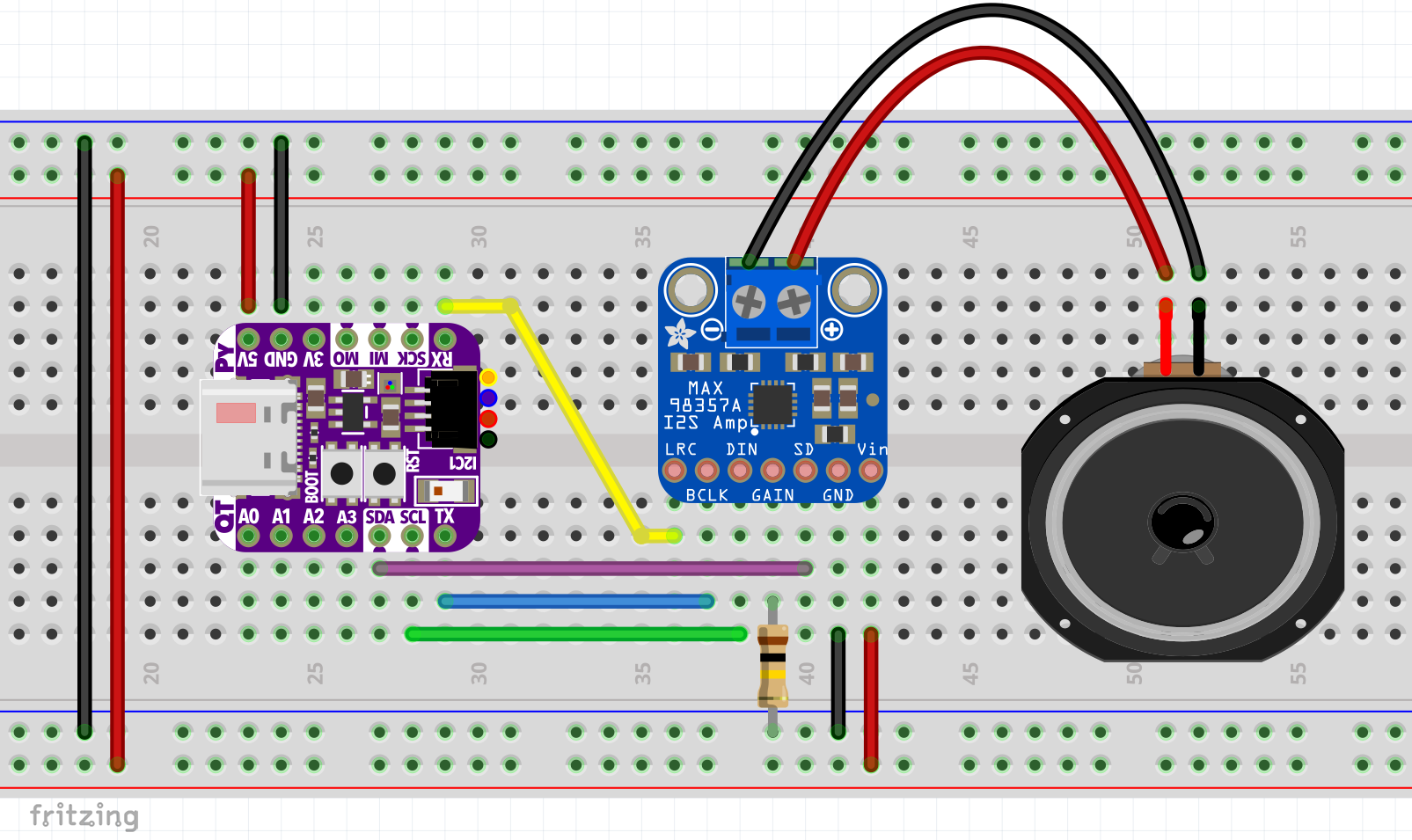
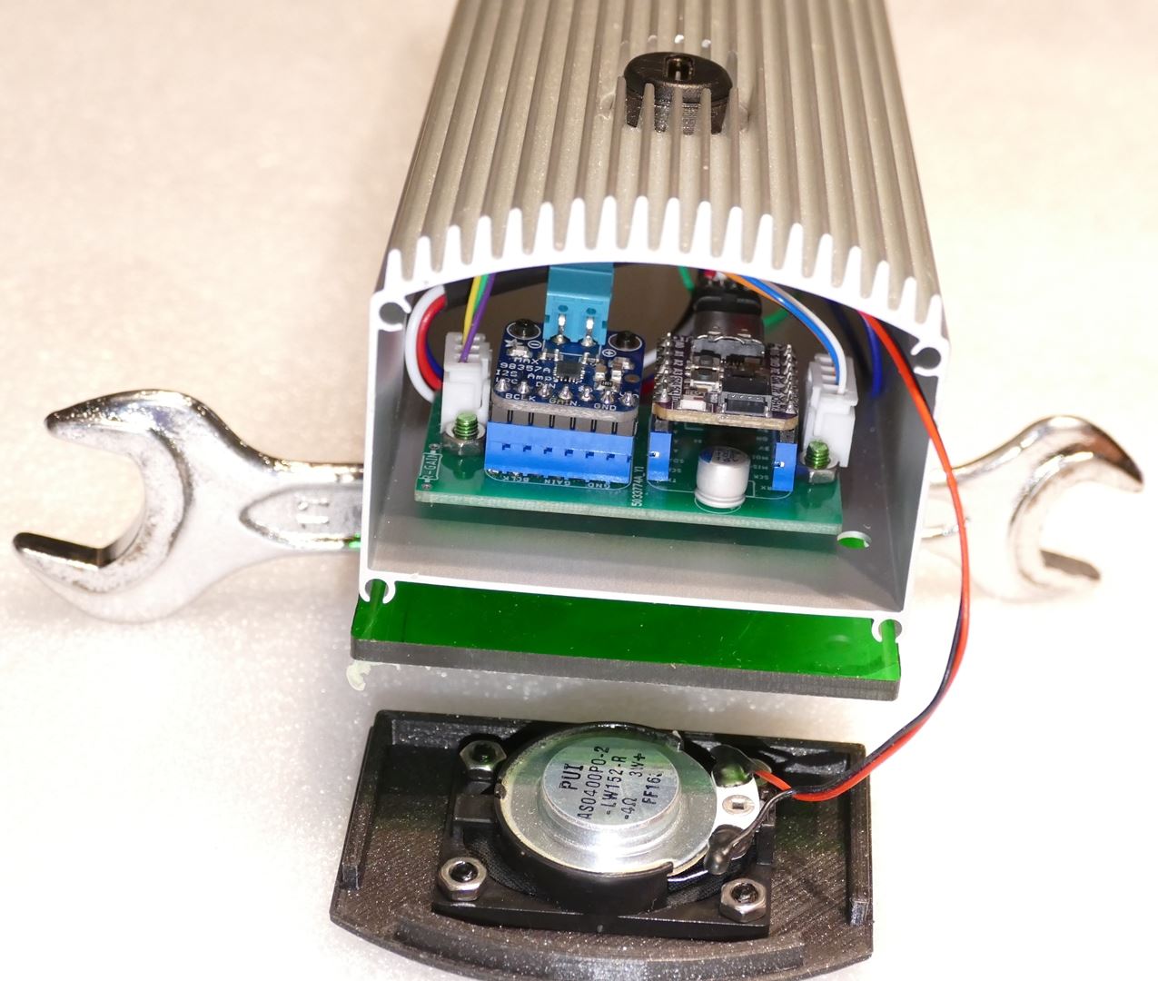
In addition to displaying messages, the message layer will also play a notification chime which will require audio output. I wanted to use the Adafruit STEMMA speaker with built-in amp because it is inexpensive and only requires a single GPIO but unfortunately the QT PY ESP32-S2 does not currently support the audioio library or the audiopwmio library. Therefore, I decided to use the same Adafruit I2S amp (Max 98357A) that I used in my BLE Restroom Key Tracker project. Wiring the amp requires a lot more connections. LRC (Left/Right Frame Clock) is connected to the QT PY’s RX pin. BCLK (Bit Clock Input) is connected to TX. DIN (Data Input) is connected to SCL. The Gain pin is used to adjust the amp gain from 3 to 15 dB (see Table 8 in the datasheet). A 100k Ω resistor to ground sets the gain at 15 dB. SD (Shut Down) is connected to SDA. By the way, you can use any pins for LRC, BCLK, DIN and SD because they are specified in code. The grounds are connected, and Vin is connected to 5V to maximize the possible output volume. The positive and negative speaker terminals are connected to a 4 Ω 3 watt speaker. I’m using a PUI Audio AS04004PO-2-LW152-WR-R.
The message layer class will use a BDF font which affords lots of possibilities. A bitmap_label is used because the message is only displayed once. Since there is no updating of the label, flicker won’t be an issue and it will use less memory. Although I found both labels to be inefficient. For example, every minute update to the clock uses over 6K of memory. It will eventually be recovered by garbage collection but when you have a big program that uses a lot of memory it’s not ideal. The displayed message can span multiple lines so wrap_text_to_lines is also imported. The audiobusio class is for I2S. The audiocore class is used to play a Wave audio file which stores a pleasant chime sound as opposed to the shrill beeps of a piezo buzzer. DigitalInOut and Direction will be used to control the amp’s shut down pin. A display IO group will hold the message label. Microcontroller Pin is only imported for the typing of the passed parameters. Sleep is used for the message duration.
"""Message Layer"""
from adafruit_bitmap_font.bdf import BDF
from adafruit_display_text import bitmap_label, wrap_text_to_lines
import audiobusio
import audiocore
from digitalio import DigitalInOut, Direction
from displayio import Group
from microcontroller import Pin
from time import sleep
The message class is passed GPIO pins for the I2S bit_clock (BCLK), word_select (LRC), data (DIN) and amp_enable (SD). A BDF font is passed along with the Display IO group. The audiobus I2SOut is instantiated. Audiocore is used to load a Wave file of the chime. The Shut Down pin is configured to the output amp_enable. This will let the main program power down the amp to save electricity when not in use. The bitmap_label is instantiated with the font, single line spacing and the coordinates are zeroed.
class Message:
    """Display and handle SMS messages."""
    def __init__(self,
                 bit_clock: Pin,
                 word_select: Pin,
                 data: Pin,
                 amp_enable: Pin,
                 font: BDF,
                 group: Group):
        """Initialize.

        :param Pin bit_clock: Board GPIO pin for I2S bit clock
        :param Pin word_select: Board GPIO pin for I2S word select
        :param Pin data: Board GPIO pin for I2S data
        :param Pin amp_enable: Board GPIO pin for I2S amp enable
        :param BDF font: Message font
        :param Group group: Display IO group to contain message
        """
        # Initialize I2S Amplifier
        self._audio = audiobusio.I2SOut(bit_clock=bit_clock,
                                        word_select=word_select,
                                        data=data)

        # Initialize notification bell sound file
        self._bell = audiocore.WaveFile("bell2x.wav")

        # Initialize amplifier enable/disable pin
        self._amp_enable = DigitalInOut(amp_enable)
        self._amp_enable.direction = Direction.OUTPUT
        self._amp_enable.value = False

        self._font = font
        self._group = group

        # Initialize message label
        self._message_label = bitmap_label.Label(font,
                                                 anchor_point=(0, 0),
                                                 anchored_position=(0, 0),
                                                 line_spacing=1.0)
The method show_message will display the passed message on the OLED for the specified delay time. Only one message is allowed at a time, so the group is checked to make sure it doesn’t already contain the message label. The message is formatted. And is changed to & to save space. I might add more abbreviations later. Next wrap_text_to_lines is used to format the text, so it spans multiple lines if necessary. A list called prior_state will hold all existing items from the Display IO group so the display can be returned to its previous state after the message. The group is also cleared while the prior_state is populated. Next the _message_label is appended to the group which displays it on the OLED. The I2S amp is enabled, and the notification chime is played through the speaker. Afterwards the amp is disabled. The sleep method leaves the message on the screen for the specified delay time. Then the message is cleared by removing the message label from the group which is then restored to its previous state.
    def show_message(self, message: str, delay: int) -> None:
        """Show the message for specified delay in seconds.

        :param str message: The message to display
        :param int delay: The delay in seconds to show message
        """
        # Confirm message not already displayed
        if self._message_label in self._group:
            return

        # Message formatting
        message = message.replace(" and ", " & ")  # Abbreviate and
        self._message_label.text = "\n".join(wrap_text_to_lines(message, 21))

        # Store Display IO group state and clear
        prior_state = []
        for i in range(len(self._group)):
            prior_state.append(self._group.pop())

        # Display message
        self._group.append(self._message_label)

        # Play notification bell sound
        self._amp_enable.value = True
        self._audio.play(self._bell)
        while self._audio.playing:
            pass
        self._amp_enable.value = False

        sleep(delay)

        # Clear message
        self._group.remove(self._message_label)

        # Restore prior Display IO group state
        for i in range(len(prior_state)):
            self._group.append(prior_state[i])
A deinit method is added so the main program can clean up the I2S audio on exit.
    def deinit(self) -> None:
        """Deinitialize class."""
        self._bell.deinit()
        self._audio.deinit()
Password Layer
The password layer has several imports. BDF font will be used for the password text displayed on the OLED. Bitmap labels will hold the Wi-Fi password text and the SSID text. L and QRCode are imported from adafruit_miniQR to generate the Wi-Fi QR code. Bitmap, Group, Palette and TileGrid are imported from display IO to handle the above text and graphics. Getenv is imported from os to get access to the Wi-Fi SSID and password. The terminalio font is used for the SSID label. Color constants white and black are defined and the QR code border-pixels is set to 2.
"""Password Layer"""
from adafruit_bitmap_font.bdf import BDF
from adafruit_display_text.bitmap_label import Label
from adafruit_miniqr import L, QRCode
from displayio import Bitmap, Group, Palette, TileGrid
from os import getenv
from terminalio import FONT

WHITE = 0xFFFFFF
BLACK = 0x000000
BORDER_PIXELS = 2
The password constructor is passed the fonts, the display IO group and the width & height of the display. An instance variable _visible will handle the layer’s visibility and like the clock layer an offset will be used to prevent OLED burn-in. A QR code is instantiated. The add_data method is passed the necessary data for the Wi-Fi connection. The make method generates the QR code in memory. Qr_bitmap will be a graphical version of the QR matrix to display on the OLED. The bitmap width is stored. Scale fits the QR bitmap to the display. Pos_y vertically centers the QR bitmap. A 2 color QR palette is defined and passed the constants for black and white. A display IO tile grid is instantiated to hold the QR bitmap. A display IO label _wifi_label holds the SSID in the smaller font. A display IO label _password_label holds the password text in the larger font.
class Password:
    """Display and handle Wi-Fi password layer."""
    def __init__(self,
                 small_font: FONT,
                 large_font: BDF,
                 group: Group,
                 display_width: int,
                 display_height: int):
        """Initialize.

        :param Font small_font: Wi-Fi password label font
        :param BDF large_font: Password font
        :param Group group: Display IO group to contain password
        :param int display_width: Width of OLED display
        :param int display_height: Height of OLED display
        """
        self._small_font = small_font
        self._large_font = large_font
        self._group = group
        self._display_width = display_width
        self._display_height = display_height
        self._visible = False
        self._offset = 0
        # Generate QR code for Wi-Fi
        qr = QRCode(qr_type=3, error_correct=L)
        # Format data for Wi-Fi connect
        qr.add_data(f"WIFI:S:{getenv('CIRCUITPY_WIFI_SSID')};T:WPA;P:" +
                    f"{getenv('CIRCUITPY_WIFI_PASSWORD')};;")
        qr.make()

        # Generate the 1-pixel-per-bit bitmap
        qr_bitmap = self._bitmap_qr(qr.matrix)
        self._bitmap_width = qr_bitmap.width

        # Scale the QR code as big as the display can handle
        scale = min(self._display_width // qr_bitmap.width,
                    self._display_height // qr_bitmap.height)
        pos_y = int(((self._display_height / scale) - qr_bitmap.height) / 2)

        # Define palette for QR codes
        qr_palette = Palette(2)
        qr_palette[0] = WHITE
        qr_palette[1] = BLACK

        # Initialize tile grid to contain QR code
        self._qr_code = TileGrid(qr_bitmap,
                                 pixel_shader=qr_palette,
                                 x=0,
                                 y=pos_y)

        # Initialize Wi-Fi label
        self._wifi_label = Label(self._small_font,
                                 text=(f"{getenv('CIRCUITPY_WIFI_SSID')}" +
                                       " Wi-Fi Password:"),
                                 color=WHITE,
                                 anchor_point=(0, 0),
                                 anchored_position=(qr_bitmap.width + 8, 16))
        # Initialize password label
        self._password_label = Label(self._large_font,
                                     text=getenv('CIRCUITPY_WIFI_PASSWORD'),
                                     color=WHITE,
                                     anchor_point=(0, 0),
                                     anchored_position=(qr_bitmap.width
                                                        + 8, 29))
A static method _bitmap_qr generates the QR code bitmap. It is passed the QR matrix. It creates a new bitmap using the matrix dimensions along with the border_pixels. Next the method loops through the complete X, Y range of the matrix to build the bitmap pixel by pixel. The bitmap is returned.
    @staticmethod
    def _bitmap_qr(matrix):
        """ Generate Display IO bitmap from QR matrix"""
        # Define bitmap to hold QR code
        bitmap = Bitmap(matrix.width + 2 * BORDER_PIXELS,
                        matrix.height + 2 * BORDER_PIXELS,
                        2)
        # Raster the QR code
        for y in range(matrix.height):  # each scanline in the height
            for x in range(matrix.width):
                if matrix[x, y]:
                    bitmap[x + BORDER_PIXELS, y + BORDER_PIXELS] = 1
                else:
                    bitmap[x + BORDER_PIXELS, y + BORDER_PIXELS] = 0
        return bitmap
Like the other display layers, there is a visible property. The setter will add the QR code, the SSID label and the password label to the display IO group if visible is true. Otherwise, it will remove all 3 if visible is false.
    @property
    def visible(self) -> bool:
        """Is the password layer visible."""
        return self._visible

    @visible.setter
    def visible(self, show: bool) -> None:
        """Set password layer visibility"""
        self._visible = show
        if show:
            if self._qr_code not in self._group:
                self._group.append(self._qr_code)
            if self._wifi_label not in self._group:
                self._group.append(self._wifi_label)
            if self._password_label not in self._group:
                self._group.append(self._password_label)
        else:
            if self._qr_code in self._group:
                self._group.remove(self._qr_code)
            if self._wifi_label in self._group:
                self._group.remove(self._wifi_label)
            if self._password_label in self._group:
                self._group.remove(self._password_label)
The offset property allows the program to horizontally shift the QR code, the SSID label and the password text to avoid OLED burn-in.
@property
    def offset(self) -> int:
        """Horizontal offset."""
        return self._offset

    @offset.setter
    def offset(self, length: int) -> None:
        """Set horizontal offset"""
        self._offset = length
        self._qr_code.x = self._offset
        self._wifi_label.anchored_position = (self._bitmap_width
                                              + 8 + self._offset, 16)
        self._password_label.anchored_position = (self._bitmap_width
                                                  + 8 + self._offset, 29)
Main Program
The main program has a lot of imports. The adafruit_bitmap_font library is imported for BDF fonts. The adafruit_minimqtt library is imported for MQTT. The adafruit_ssd1322 library is imported for the SSD1322 OLED display. The required GPIO pins and SPI bus are imported from board. The displayio library is imported for the display text and graphics. The garbage collection (gc) is imported to address some memory issues (no pun intended). The microcontroller library is imported. From os, getenv is imported to access environment variables. SocketPool is for network sockets. The ssl module with afford secure Internet access. The supervisor module is imported. Terminalio is used for its font. From time, sleep is imported. The wifi module provides Wi-Fi networking. The 4 display layer classes are imported for Clock, Disconnection, Message and Password. Finally, my mqtt_manager is imported to manage MQTT.
from adafruit_bitmap_font import bitmap_font
import adafruit_minimqtt.adafruit_minimqtt as mqtt
import adafruit_ssd1322
from board import D6, D7, D9, D17, D18, RX, TX, SPI
import displayio
import gc
import microcontroller
from os import getenv
from socketpool import SocketPool  # For MQTT & NTP
import ssl
import supervisor
import terminalio
from time import sleep
import wifi
from clock_layer import Clock
from disconnection_layer import Disconnection
from message_layer import Message
from password_layer import Password
from mqtt_manager import MQTTManager
A client_id that is unique to each QT PY board is created by taking the least significant 19 bits of the microcontroller.cpu.uid. I ran into a strange bug with respect to running multiple QT PY boards on the same network. By default, all the QT PY ESP32 boards default to the network hostname “espressif”. For an unknown reason this was intermittently causing the boards to disconnect and core crash. I don’t know if the problem is specific to my Asus router. However, after assigning unique hostnames, the crashing hasn’t reoccurred. Also, unique names help to identify stuff when you’re using networking tools.
# Generate a unique 19-bit WiFi client hostname using CPU UID
client_id = 'QTPY' + str(int.from_bytes(microcontroller.cpu.uid, 'little')
                         >> 29)
if wifi.radio.hostname != client_id:
    wifi.radio.hostname = client_id
print(f'WiFi Hostname: {wifi.radio.hostname}')
The display IO release_displays method is called to ensure any existing displays are released. The SPI bus for the display is instantiated and passed the necessary board parameters. The baud rate is set at what I would consider a conservative speed to favor reliability of speed. The display is instantiated and passed the bus, the width, the height and I found it necessary to modify the default colstart value to 112 for my particular OLED display. This is supposed to be the index of the first visible display column. The display IO group is defined. This is the group that all the 4 display layers will use to display text and graphics. A small font is defined using terminalio font and a large font is defined using the bitmap_font load_font method which is passed the path to the font file profont22.bdf.
# Ensure that Display IO releases any existing displays
displayio.release_displays()

# Initialize SSD1322 OLED display
spi = SPI()  # SPI pins labeled SCK, MOSI (MISO not used)
dc = D9  # D9 labeled A2
cs = D18  # D18 labeled A0
reset = D17  # D17 labeled A1
display_bus = displayio.FourWire(spi, command=dc, chip_select=cs,
                                 reset=reset, baudrate=5000000)
display = adafruit_ssd1322.SSD1322(display_bus, width=256, height=64,
                                   colstart=112)

# Initialize group to hold all display graphics
group = displayio.Group()

small_font = terminalio.FONT
large_font = bitmap_font.load_font("/profont22.bdf")
The function connect_to_wifi establishes a Wi-Fi connection. I’m using a settings.toml file to store my SSID and password so CircuitPython should automatically connect to Wi-Fi. However, despite what the docs say CircuitPython currently doesn’t automatically reconnect if the connection is dropped. Hopefully this will change in the future. Therefore, the ipv4_address is checked and if there isn’t one then that means there is no Wi-Fi connection. The function will loop until an address obtained. The wifi.radio connect method is passed the SSID and password from the environment variables stored in the settings.toml file. As always with networking operations, error catching is used. The function will repeat every 10 seconds until a Wi-Fi connection is established.
def connect_to_wifi():
    """Connect to Wi-Fi."""
    print(f'Connecting to {getenv("CIRCUITPY_WIFI_SSID")}...')
    while not wifi.radio.ipv4_address:
        try:
            wifi.radio.connect(getenv('CIRCUITPY_WIFI_SSID'),
                               getenv('CIRCUITPY_WIFI_PASSWORD'))
        except (ConnectionError) as con_err:
            print("Connection Error:", con_err)
            print("Retrying in 10 seconds")
        sleep(10)
    print(f'Connected to {getenv("CIRCUITPY_WIFI_SSID")}')
At this point the program checks for a Wi-Fi connection and calls the above connect_to_wifi function if not. A SocketPool is defined which will be used by the NTP and MQTT protocols. The clock_layer is instantiated to handle the display of the clock. The disconnection_layer is instantiated to handle the display of the disconnection error icon. The message_layer is instantiated to handle display of SMS text messages. The password_layer is instantiated to handle display of the SSID, Wi-Fi password and QR code.
if not wifi.radio.ipv4_address:
    connect_to_wifi()

# Initialize socket pool
pool = SocketPool(wifi.radio)

# Initialize clock
clock_layer = Clock(font=small_font,
                    group=group,
                    pool=pool,
                    display_width=display.width,
                    display_height=display.height)

# Initialize disconnection layer
disconnection_layer = Disconnection(group=group)

# Initialize message layer
message_layer = Message(bit_clock=TX,
                        word_select=RX,
                        data=D6,
                        amp_enable=D7,
                        font=large_font,
                        group=group)

# Initialize Wi-Fi password layer
password_layer = Password(small_font=small_font,
                          large_font=large_font,
                          group=group,
                          display_width=display.width,
                          display_height=display.height)
A callback function called message will fire when an SMS text message is received. The text is cleaned up for more flexibility with the commands. Any non-letters are removed and the case is set to upper. This allows a user to issue the WIFI command by also typing Wifi, Wi-Fi, wifi, etc. If clean_text = “WIFI” then clock scale is set to 1 to make room for the password_layer which is made visible. This shows the SSID, the password and the QR code on the display. If clean_text = “OFF” then the password_layer is turned off and the clock scale is made large to fill the display. The reset command will restart the QT PY board. I did run into some bugs with the display IO library where after a few days, artifacts started appearing on the screen. if it reoccurs then anyone in the office can reset all the displays by texting reset. I may add more commands later on. The final else indicates the text message is not a command so the message_layer is enabled and passed the full text message along with the delay time of 10 seconds.
def message(message):
    """Callback fired when topic has new message."""
    clean_text = "".join(c.upper() for c in message if c.isalpha())
    if clean_text == "WIFI":
        # Adjust clock scale so it doesn't block Wi-Fi password
        clock_layer.scale = 1
        # Display Wi-Fi QR code received
        password_layer.visible = True  # Show Wi-Fi password text & QR code
    elif clean_text == "OFF":
        # Clear display
        password_layer.visible = False
        clock_layer.scale = 2
    elif clean_text == "RESET":
        # Reboot the microcontroller
        microcontroller.reset()  # Same as pressing reset button
    else:
        # Display SMS text message
        message_layer.show_message(message=message, delay=10)
An mqtt_client is instantiated. If you don’t pass a client_id then one will automatically be generated. However, I found the connection to be more reliable by always specifying the same unique client ID per board. Therefore, I’m using the same one generated for the hostname from the CPU ID. The broker address is retrieved from the settings.toml file along with the port number, the username and the security key. The socket pool is passed and ssl.create_default_context is used to secure the Internet communication. The mqtt_manager is instantiated and passed the mqtt_client and the callback function to be fired when a message is received. The connect method is called to establish the MQTT connection with Adafruit IO. A variable last_hour is set to -1. It is used to keep track of when the hour of day changes. The clock_layer is enabled and display.show is called to actually display the main group.
# Set up a MiniMQTT Client
mqtt_client = mqtt.MQTT(
    client_id=client_id,
    broker=getenv("BROKER"),
    port=int(getenv("PORT")),
    username=getenv("AIO_USERNAME"),
    password=getenv("AIO_KEY"),
    socket_pool=pool,
    ssl_context=ssl.create_default_context(),
)

# Initialize MQTT manager and connect
mqtt_manager = MQTTManager(mqtt_client, message)
mqtt_manager.connect()

last_hour = -1
clock_layer.visible = True  # Show clock
display.show(group)  # Show DisplayIO group on OLED display
The main program loop is an infinite while wrapped in a try to catch errors. The clock_layer parse_time method is called to update the time and date if necessary and returns the current hour. If the hour does not equal the last hour, then hourly routines are performed. In order to mitigate bugs and improve reliability, a soft restart is performed using supervisor.reload. It occurs once daily at midnight when the hour equals zero and the last hour was 23. Otherwise, the last_hour is updated to the current hour. The available memory is printed to the REPL to aid in debugging. Every hour the password_layer offset is cycled through 1 of 4 positions to reduce OLED burn-in. The clock_layer offset is also adjusted plus or minus up to 12 pixels from noon. Our business hours are typically 5 AM to 5 PM so the password_layer is automatically hidden outside these times in case someone forgets to turn it off. Then the OLED is given a rest between 9 PM and 5 AM. Next the Wi-Fi connect is checked using the ipv4_address. If the Wi-Fi has dropped, the mqtt_manager status is set to disconnected, the disconnection_layer is made visible to show the error icon and the connect_to_wifi function is called. Afterwards the loop is restarted. Otherwise, the mqtt_manager loop method is called to check for text messages. If true is returned, then everything worked and the disconnection_layer can be hidden if necessary. I did find it necessary to use gc.collect to force the python garbage collection each loop because I ran into memory issues especially with display IO. Hopefully, these will get better as CircuitPython continues to mature. The loop sleeps for 1 second and repeats. An except statement is added to catch Ctrl-C and gracefully exit by putting the display to sleep, releasing display IO and deinitializing the mqtt_client, the message_layer and the SPI bus.
# Main program loop
try:
    while True:
        # Update clock
        hour = clock_layer.parse_time()

        # Hourly checks
        if hour != last_hour:
            # Soft reload daily to address CircuitPython bugs
            if hour == 0 and last_hour == 23:
                supervisor.reload()
            last_hour = hour
            print(f'Free memory: {gc.mem_free()}, hour: {hour}')

            # Adjust Wi-Fi QR / password X position to avoid burn-in
            password_layer.offset = hour - (4 * (hour // 4))

            # Adjust clock position to avoid burn-in
            clock_layer.offset = hour - 12

            # Hide displayed Wi-Fi password if outside business hours
            if hour < 5 or hour > 17:
                password_layer.visible = False
                clock_layer.scale = 2

            # Show or hide clock depending on extended business hours
            if 5 <= hour <= 21:
                clock_layer.visible = True
            else:
                clock_layer.visible = False

        # Check Wi-Fi is connected
        if wifi.radio.ipv4_address is None:
            mqtt_manager.status = "DISCONNECTED"
            disconnection_layer.visible = True
            connect_to_wifi()
            continue

        if mqtt_manager.loop():
            disconnection_layer.visible = False

        gc.collect()
        sleep(1)
except KeyboardInterrupt:
    print("\nCtrl-C pressed.  Cleaning up...")
finally:
    display.sleep()
    displayio.release_displays()
    mqtt_client.deinit()
    message_layer.deinit()
    spi.deinit()
Environment Variables
Here are the environment variables used in this tutorial. CircuitPython 8.0.0 introduces support for environment variables. CircuitPython uses a file called settings.toml at the drive root (no folder) as the environment. Environment variables are commonly used to store “secrets” such as Wi-Fi passwords and API keys. This method does not make them secure. It only separates them from the code so be careful not to post them to a public website such as GitHub. Don’t worry, I’m going to change my Wi-Fi password, regenerate my Adafruit IO key and change my Twilio phone number.
# To auto-connect to Wi-Fi
CIRCUITPY_WIFI_SSID="Rototron"
CIRCUITPY_WIFI_PASSWORD="xHd0$1*IlO6L!F"

AIO_USERNAME="rdagger"
AIO_KEY="97642f4343b049f3809849b2f5721aff"
AIO_FEED="rdagger/feeds/Rototron"
BROKER="io.adafruit.com"
PORT=8883  # Secure port SSL
TIMEZONE=-5
The Adafruit IO security key above can be obtained by clicking the key icon on the Adafruit IO website.
The following CircuitPython libraries were used in this project:
- adafruit_bitmap_font
- adafruit_bus_device
- adafruit_datetime
- adafruit_display_text
- adafruit_ds3231
- adafruit_minimqtt
- adafruit_miniqr
- adafruit_ntp
- adafruit_ssd1322
The Build
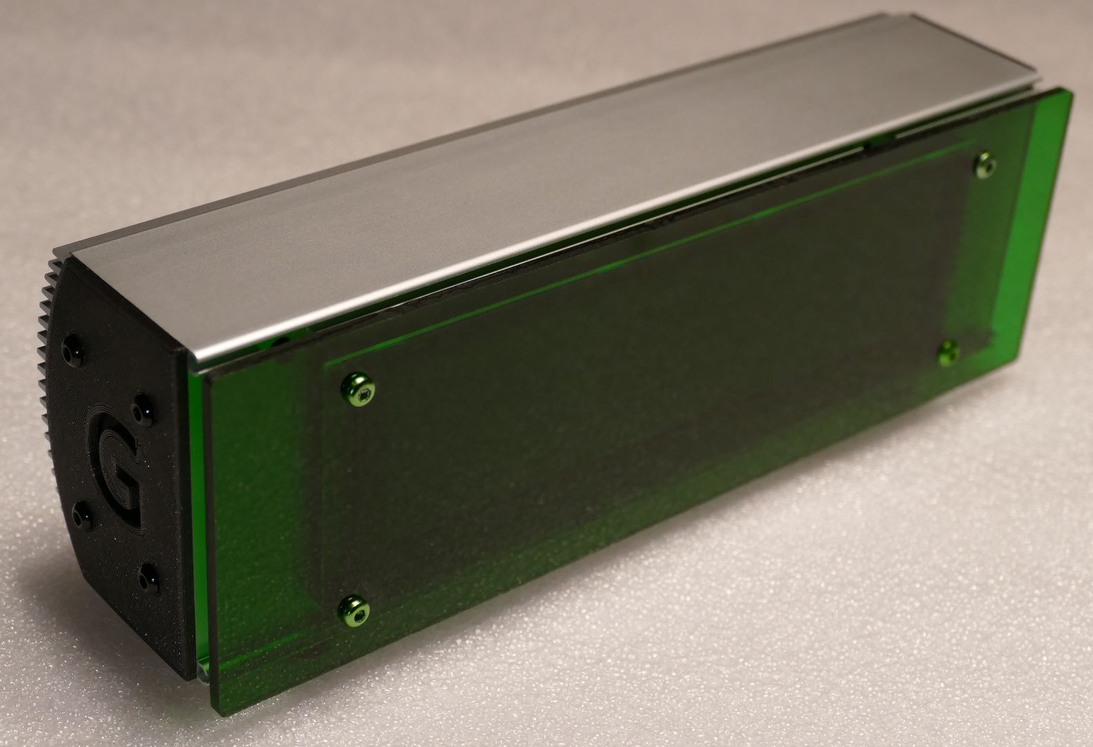
I need to build at least 4 displays and I wanted something that would look good in our conference rooms. I found an inexpensive aluminum case at my favorite electronics surplus store All Electronics.

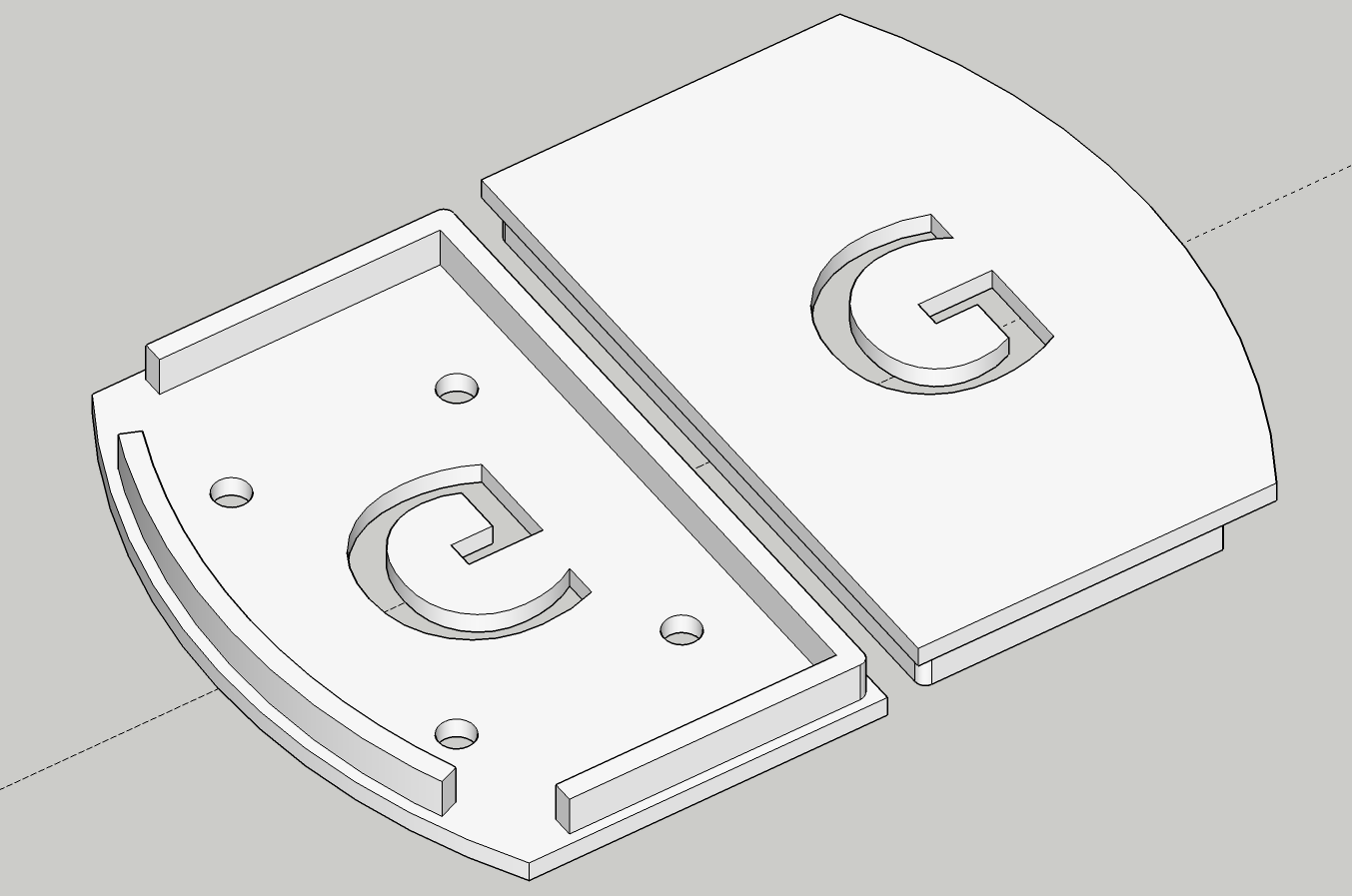
I designed 3D printed covers for the sides of the case in Sketch Up.
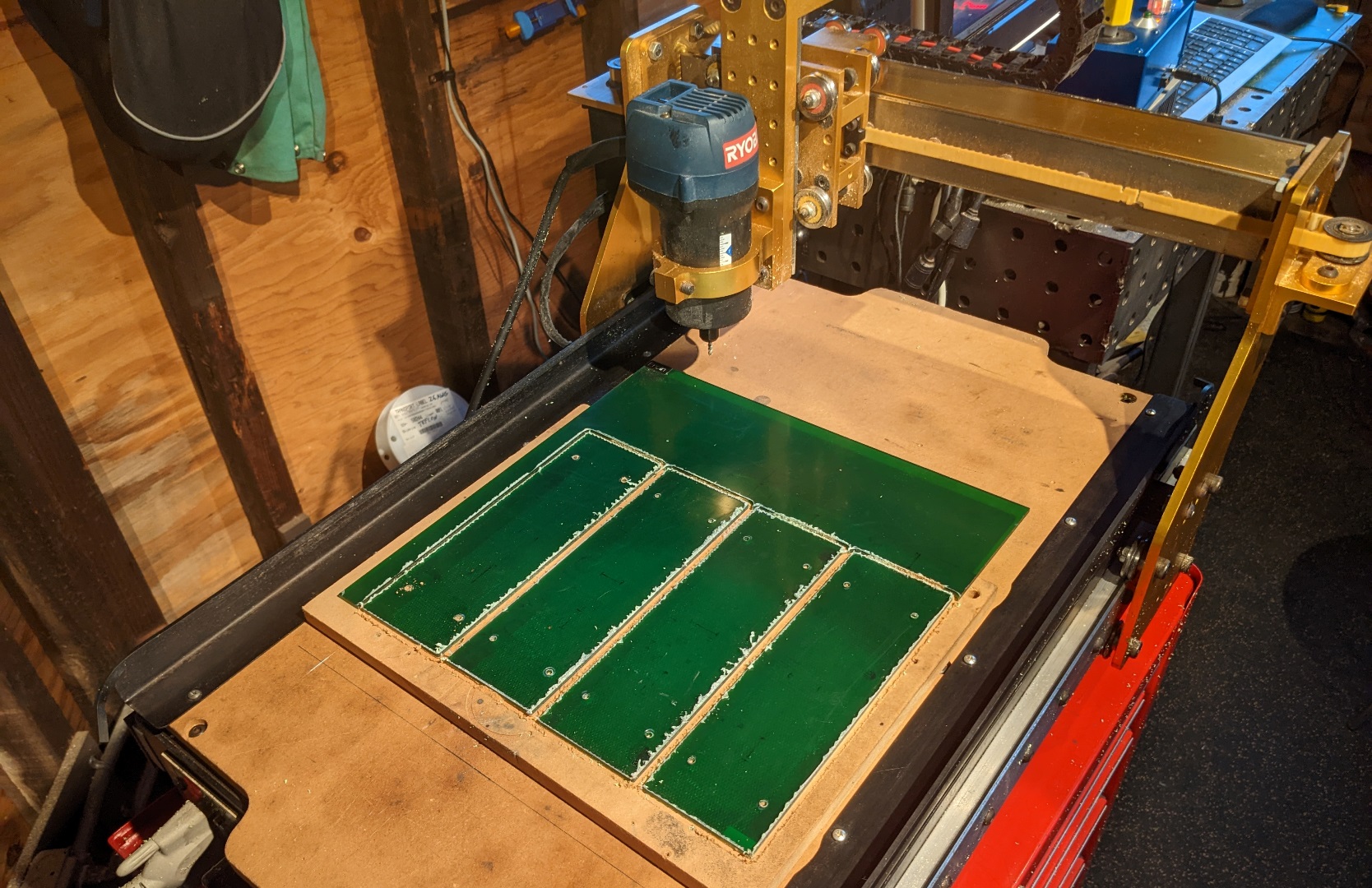
I needed 4 new holes on the front of the case to mount the OLED display and a rounded rectangular cut out to pass the wires. The aluminum case has a concave back which is hard to mount so I cut a pocket in a 2×4 with my Romaxx HS1 to hold it securely and then made the required cuts using CNC precision.

I also used the CNC to cut green plexiglass covers for the 4 cases.
In order to keep the wiring tidy, I designed a PCB in Eagle to hold the QT PY, the I2S amp and the necessary connectors.
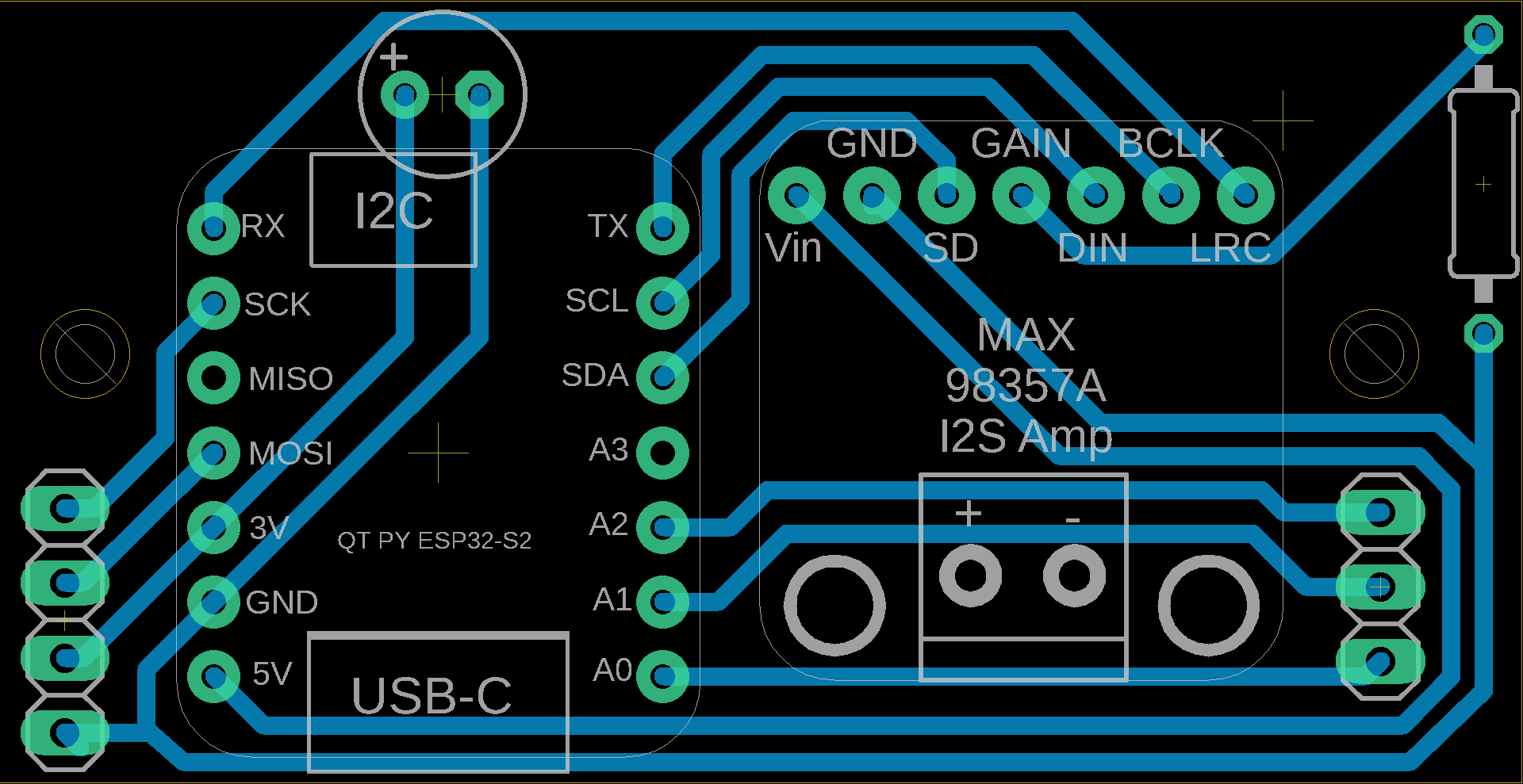
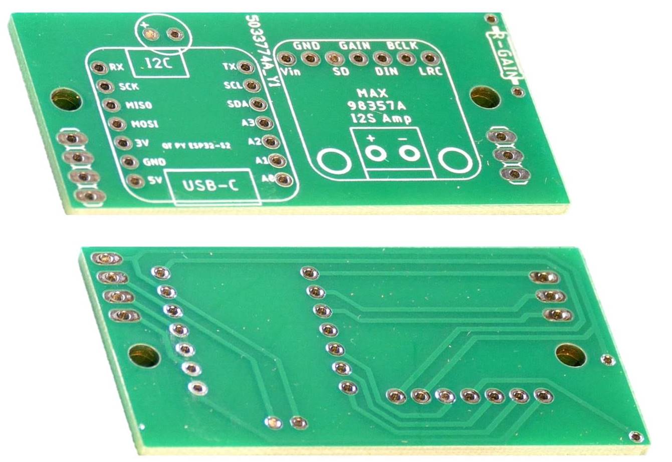
Since I needed 4 PCB’s, I ordered them online from one of the popular PCB makers.
I used 7 position female header sockets to mount the QT PY and I2S amp because quick removal greatly facilitates testing and debugging. For the same reason, I swapped out the 3.5 mm terminal block on the I2S amp for a pluggable version. Please note the through holes on the I2S amp are small so the pin diameter of your terminal block should be less than 0.8 mm. I didn’t screw down the black standoffs. The two 3D printed standoffs were created using a great Customizable Standoff Generator that I found on Thingiverse.
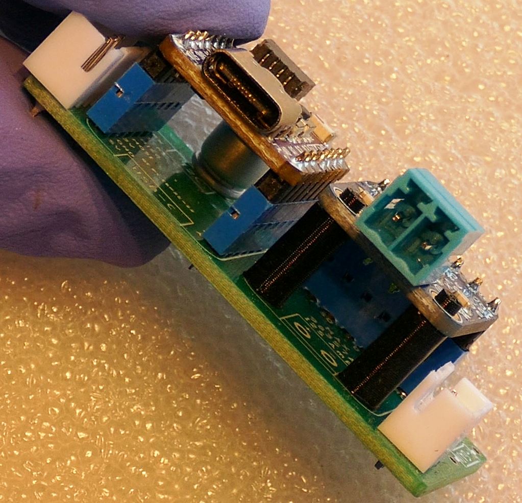
The PCB is mounted inside the enclosure using 2 of the screws that retain the OLED display. The PCB is isolated from the case by 3 mm PVC spacers. JST-XH 3 & 4 pin connectors are used to connect the OLED. I used two separate plugs because 7 pin connectors are less common. I omitted the gain resistor because the default 9 dB was loud enough. The STEMMA connector on the QT PY is located near the case opening so it can be used as a debugging console output.
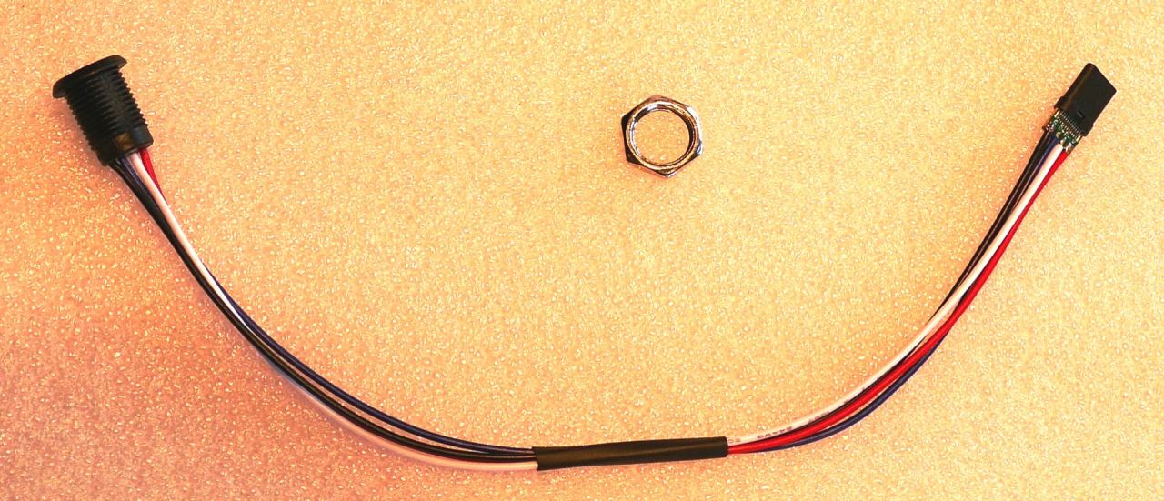
I bought a 4-wire panel mount USB Type C connector on AliExpress because it was the only one I could find that would fit in the 1/2 inch (12.7 mm) opening in the back of the enclosure. In retrospect, it was a bad choice because it is not fully compatible. It doesn’t work if I plug it into a Type C jack on a computer. However, it does work if I plug it into a Type A jack using a USB-C to USB-A cable. I did try all the different resistor combinations on the male plug, but I couldn’t find a compatible combination. In future projects I would just buy a very short USB C extension cable and either 3D print or CNC a panel mount for it. Alternatively, I could have just run a USB cable out the back with a strain relief grommet.
The display is mounted to the case with green anodized aluminum M3 socket cap screws. The speaker is mounted to the left cover using the same screws in black. Eight M3 x 3 mm anodized aluminum spacers are used on each side of the OLED display board to separate it from the case and the plexiglass.
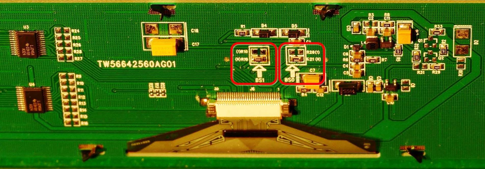
When I first tried the OLED display it didn’t work. I tracked the problem down to the configuration resistors labelled BS0 and BS1. I had ordered the 4-wire SPI display but mine was set up for 8080 parallel. I had to move the zero ohm resistor labelled R18 to the R19 position as shown below. R21 was already in the correct position. The configuration options are detailed in the interfacing instructions.
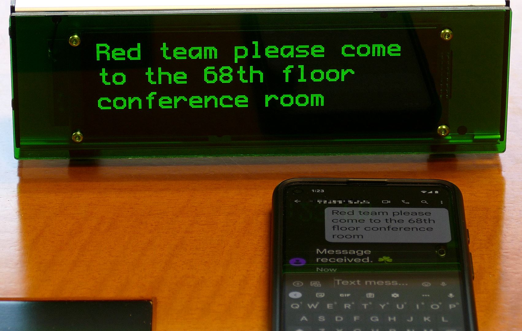
The displays shows a text message sent from a mobile phone and the phone gets a “Message received” confirmation text from Twilio. Of course, the phone doesn’t need to be next to the display. The text message could be sent from anywhere in the world with cell service. Furthermore, I ended up making 4 displays and they could be spread out across the world in different locations and as long as they have Wi-Fi they’ll work.
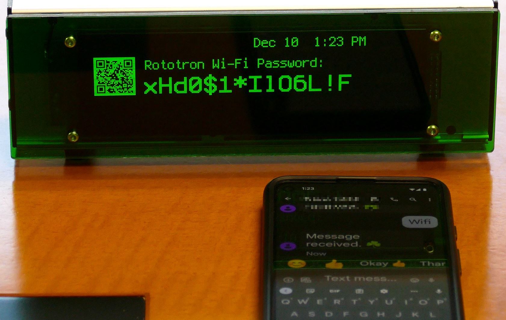
When the message “Wifi” is texted, the display shows the Wi-Fi information. Notice the clock is reduced in scale and moved to the top right corner.
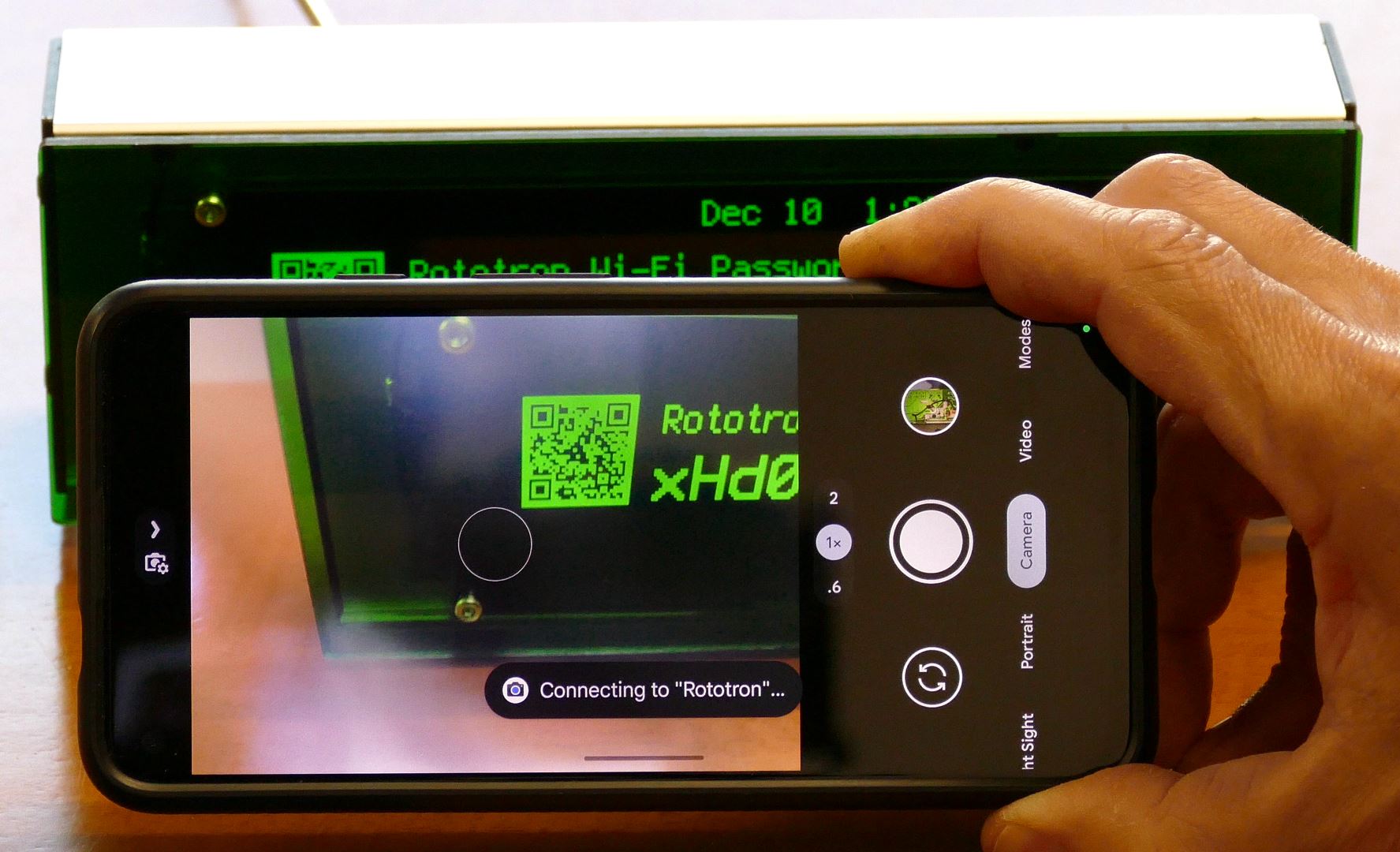
The QR code can be scanned by a mobile device, and it will automatically be connected to the Wi-Fi network.
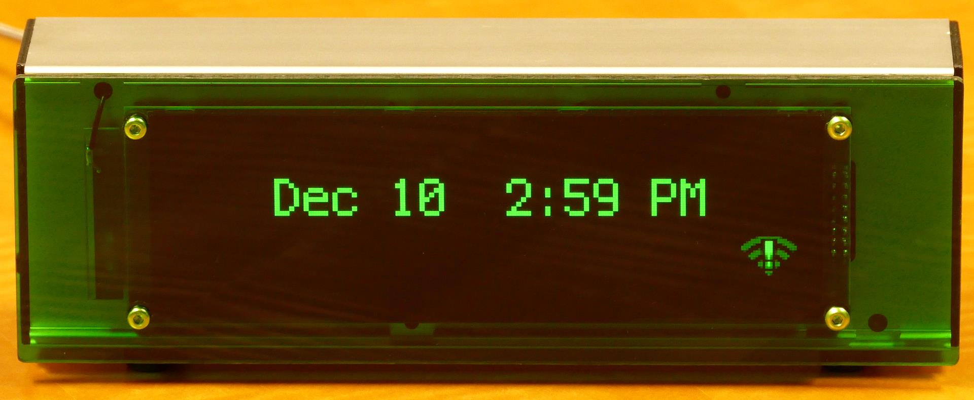
When the MQTT connection is dropped, the disconnection error icon appears on the bottom right side of the screen. The QT PY ESP32-S2 is available in 2 models. One has a built-in Wi-Fi antenna on the PCB. The other has a uFL antenna port. This particular display was place a good distance from an access point so I opted for an external 2.4 GHz antenna which if you look carefully is mounted just to the left of the OLED display.
Downloads
- CircuitPython Code (12-31-2022)
- Twilio Code (01-03-2023)
- Eagle Schematics & Board (12-13-2022)
- Sketchup & STL Files (12-13-2022)
- VCarve CNC Files (12-17-2022)