
I found this article on Bit-Tech that describes how to build a rainbow LED circuit. I followed the plans and built a prototype circuit on a breadboard.
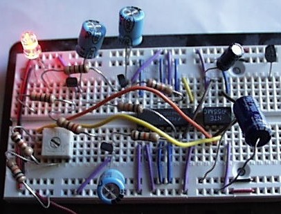
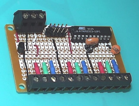
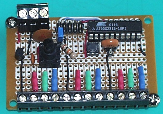
The circuit works well, but I thought I could improve on it and I had some spare AVR chips left over from my Rotary Interface. I came up with a new design from scratch that only requires 1 chip, a few resistors and a crystal. Like all my AVR circuit there is an ISP jack for in system programming. The AVR controls the RGB LED’s using pulse width modulation. With my design the RGB LED can produce about the same number of colors as a computer screen. Here is the completed circuit designed to power 3 separate RGB LED’s.
| Parts | Qty | Cost |
|---|---|---|
| Perf Board | 1 | $ 1.83 |
| 3 Node Terminal Strip | 1 | 0.25 |
| 12 Node Terminal Strip | 1 | 0.75 |
| Atmel AT90S2313-10PI AVR | 1 | 2.70 |
| High Reliability 25 Pin SIP Socket | 1 | 0.50 |
| 4 MHz 3 Pin Resonator | 1 | 1.00 |
| 86 Ohm Resistor | 6 | 0.30 |
| 120 Ohm Resistor | 3 | 0.15 |
| .01 μF Capacitor | 1 | 0.10 |
| Total Cost for Rainbow Circuit | $ 7.58 |
Here are the schematics. If you use more than one RGB LED, make sure you have separate resistors for each and enough amps on your power supply.
I purchased the RGB LED’s from Super Bright LEDS. Unfortunately, like computer monitors the color varies substantially among LED’s. My first code uses a linear function to fade between different colors and it does create a very soothing effect. The only problem is that the LED’s brightness does not directly correlate to the pulse length. The relationship is better modeled with an exponential curve. I came up with a formula that illuminates the LED’s in a very fluid fashion. Unfortunately, I exceeded the 2k limit on my AT90S2313 because the Bascom software does not handle singles in a very efficient manner. Nonetheless, the linear model works well for now and it is using about 86% of the chips capacity.
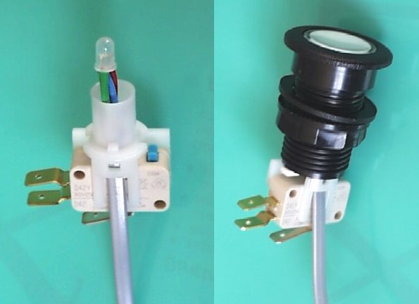
Here is a collage of photos of 1 of my Wico flush mount illuminated pushbuttons showing a few of the colors
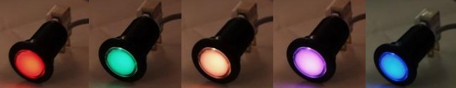
Here is side by side showing how I replaced the illuminated pushbutton bulb with an RGB LED. The LED’s come in either frosted or clear. I find that the frosted work much better for buttons, because the frosted coat blends the 3 colors together. The clear coatings are brighter, but when illuminated you can see a clear division between the colors. The two pushbuttons are located on the top corners of my CP and continuously cycle through the rainbow. One button is for pause and the other for coin insert.
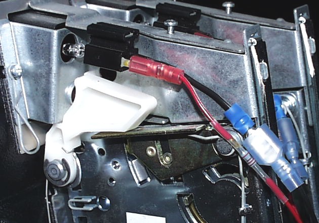
The circuit also has a 12 volt output that I use to illuminate the marquee with super bright white LED’s and a 5 volt output for the coin door (shown below) with super bright red LED’s.
Update March 4, 2006
I made a few modifications to the circuit. I added a potentiometer that I had left over from a Microsoft Dual Strike joystick that I hacked. The pot now controls the speed of the LED fading. I also added a jumper with a 10K resistor to pull the reset high. This should give the circuit a little extra protection from interference. Finally, I added a miniature pushbutton to allow me to manually reset the circuit without turning off the power.
Downloads:
Version 0.5 – Released 03/04/2006 – Added variable resistor to pin d0 to adjust fading speed.
Download code v.0.5
Version 0.4 – Initial release September 2004
Download code v.0.4
Update May 21, 2006
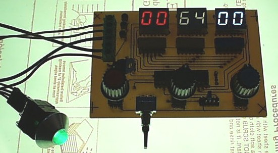
I built a new rainbow circuit from scratch. Version 2 now supports 3 dual digit color corresponding LED displays that show the current color values. There is also a switch to change modes. In mode 1, the 3 pots allow you to set a specific color. In mode 2, the circuit fades through the rainbow and the pots control the speed. I’ve added transistors to allow the circuit to light as many RGB LED’s as the power supply can handle.
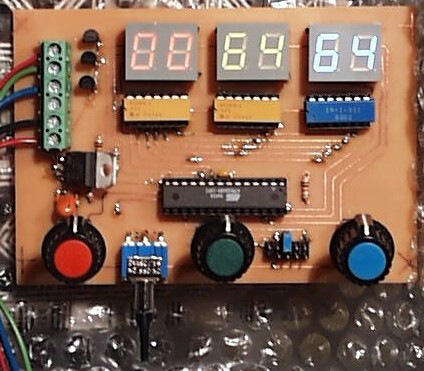
It is difficult to photograph the LED displays. Here is darkened shot of the board connected to one of my RGB Volcano Switches:
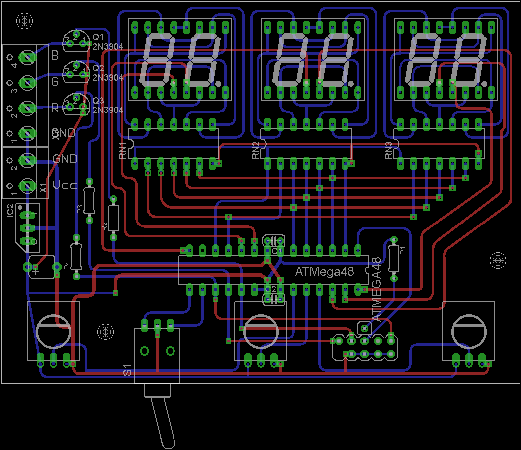
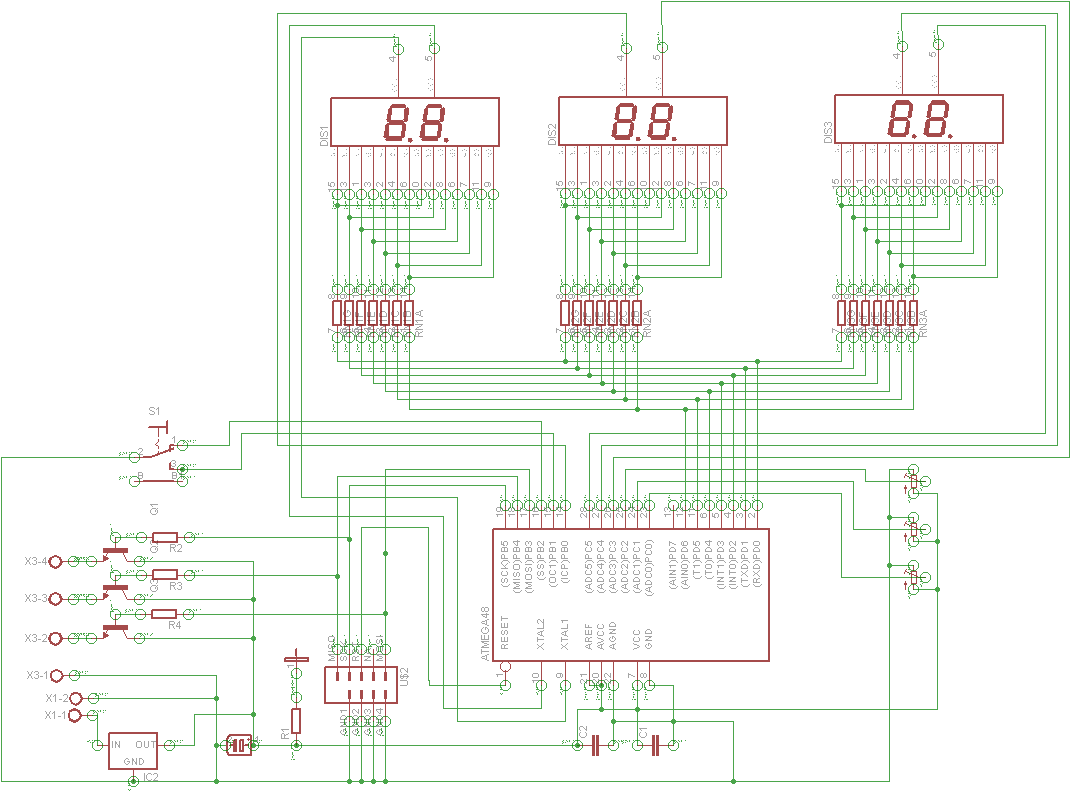
Eagle board drawing & schematics:
Downloads:
Version 2.0b – Released 02/13/2009 – Code for redesigned board.
Download code v.2.0b
Download Eagle files. Please note that the pinouts of 7-segment LED vary.