
This tutorial demonstrates how to measure DC voltage, current and wattage using a Raspberry Pi and an INA219. This can be very useful in many applications such as measuring battery levels, estimating battery life, tracking solar power generation, monitoring the amount and cost of electricity consumption, etc.
Here’s an INA219 breakout board. It can measure voltage up to 26 V. This board has a 0.1 Ω current measuring shunt resistor which is labeled R100.
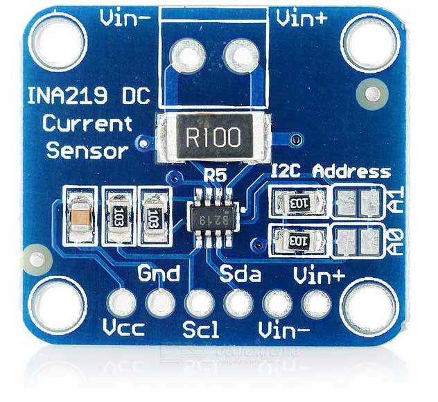
The INA219 chip can very precisely measure the voltage drop across the shunt. This is the difference between the voltage coming into the shunt and the voltage after the shunt.
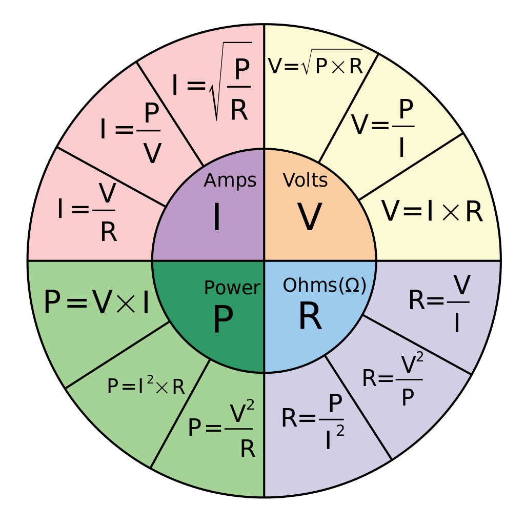
It then uses this voltage drop along with the value of the resistor shunt to determine the current flow in amps because Ohm’s law states that current (I) = voltage (V) / resistance (R). With voltage and current it can calculate wattage using power (P) = voltage(V) x current (I). The following pie chart summarizes many helpful equations.
The maximum voltage drop that the INA219 can measure is 320 mV or .32 V. Therefore the maximum current that the INA219 can measure with the default resistor is .32 V / 0.1 Ω = 3.2 A. If you need to measure more than 3.2 A it is possible to replace the 0.1 Ω shunt with a lower value. A 0.01 Ω shunt would allow 32 A current measurements.
However the lower value resistor would need to dissipate more heat so it would need to have a higher wattage rating. Power dissipation (P) = current (I)2 x resistance (R). The board’s default 3.2 A rating means the 0.1 Ω resistor needs to be able to dissipate 1.024 watts: 3.22 x 0.1 Ω = 1.024 W. Possibly more if the resistor is located near other components that generate heat. At 32 amps the power equations shows that the 0.01 Ω resistor shunt would need to be able to dissipate 10 times more watts: 322 x 0.01 Ω = 10.24 W.
Precision current measuring shunt resistors that can handle 10 watts are usually expensive and get pretty hot. Therefore, if you want to measure more than 3.2 amps I would look into a more efficient solution such as the Allegro ACS37800 that can sense voltage up to 60 VDC and current up to 30 A using hall-effect-based, galvanically isolated current sensing technology. Please exercise caution when working with dangerous currents!
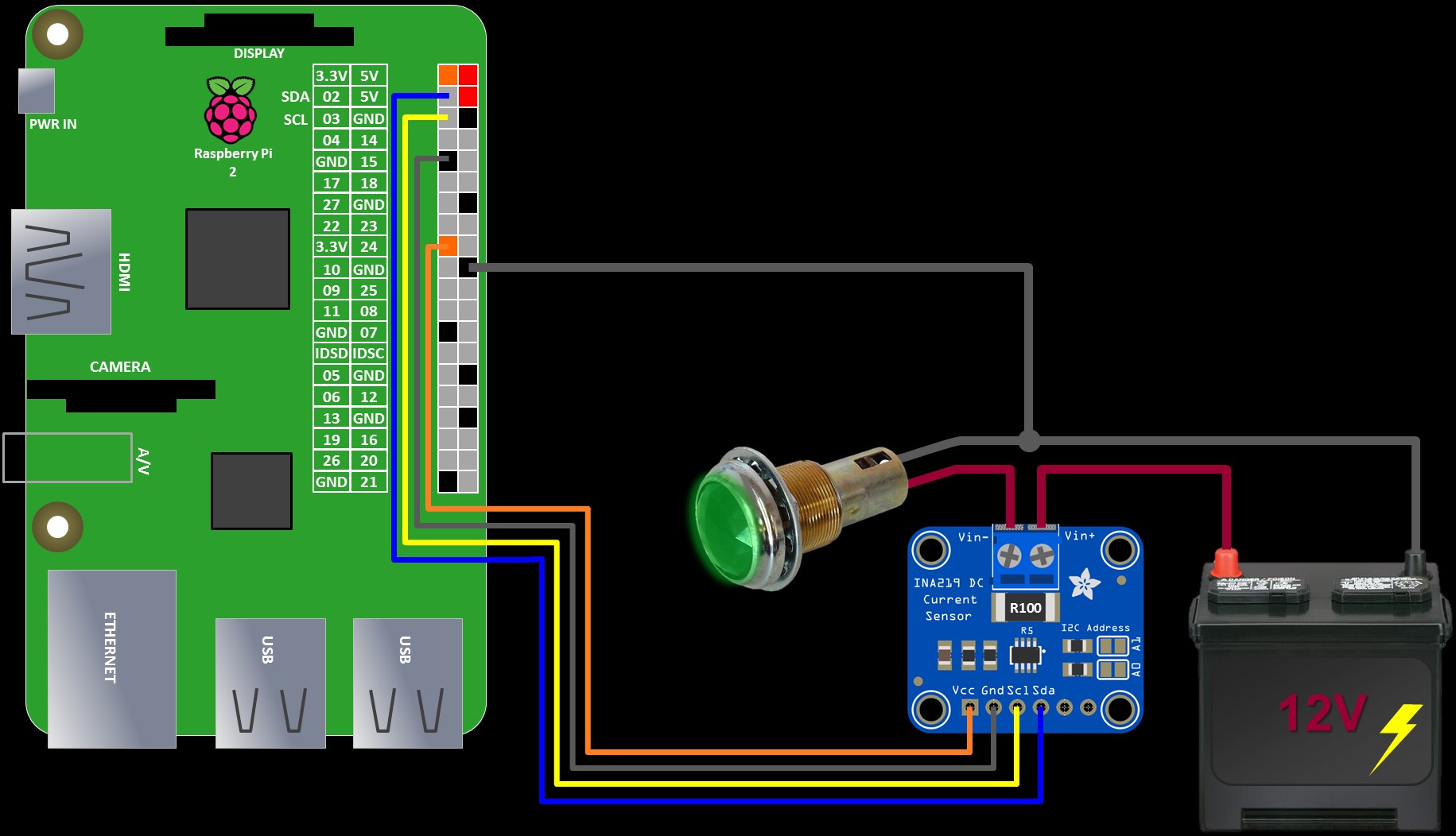
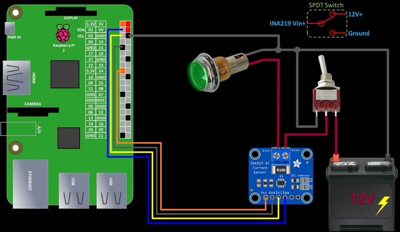
The INA219 provides digital reporting using the I2C communication protocol. Unlike an analog sensor that provides a proportional value, the digital INA219 returns actual numbers for the voltage, current and power in volts, amps and watts. I2C makes wiring the INA219 adapter to the Raspberry Pi very easy. The VCC pin is connected to a 3.3 V pin on the Pi. The ground pin is connected to a ground pin on the pi. The SDA and SCL pins are connected to SDA and SCL on the Pi which are GPIO 2 and 3 respectively. Since the INA219 runs at 3.3 V no level shifting is required. You could also daisy chain multiple I2C devices using only the 2 GPIO pins SDA and SCL. The schematic below demonstrates how to measure a 12 V indicator lamp. The positive terminal of the 12 V power source is connected to the V IN PLUS connector on the INA219. V IN MINUS is connected to one of the leads on the indicator lamp. The other lead is connected to the negative terminal on the power supply. This closes the circuit and allows current to flow. In order for the INA219 to function properly, the power source being measured must share a common ground with the Pi. Therefore, the 12 V power source negative terminal is also connected to a ground on the Pi.
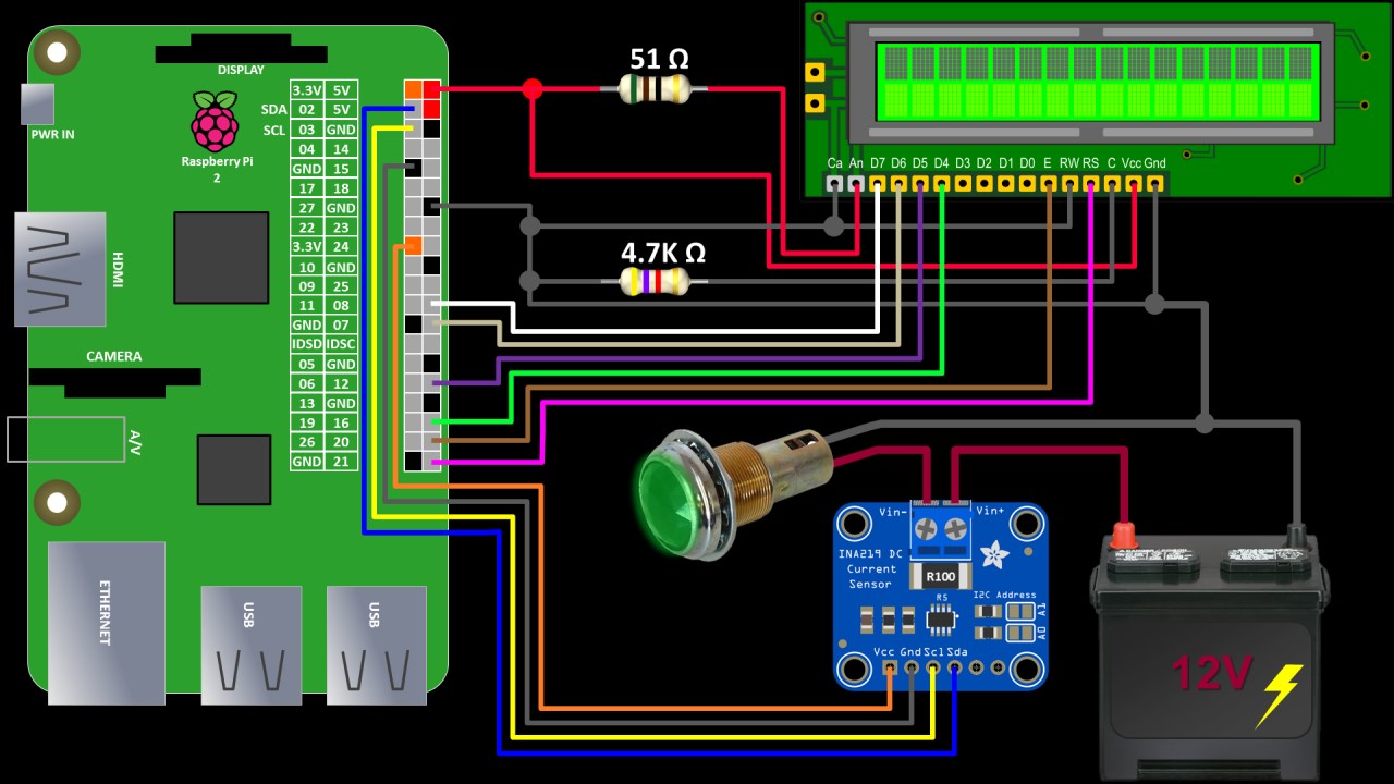
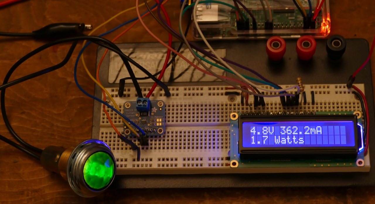
A 16×2 LCD display can be used to provide visual feedback. I have a dedicated LCD Display tutorial for more information. The ground pin of the LCD is connected to a ground on the Pi. VCC is connected to a 5 V pin on the Pi. The contrast pin is connected to ground with a 4.7 KΩ resistor in series to lower the contrast. You could also use a variable resistor for adjustable contrast or no resistor for full contrast. RS is connected to GPIO 21. The read write pin is grounded to ensure write only. The Enable pin is connected to GPIO 20. The display is used in 4 bit mode so data lines 0 – 3 are skipped and 4 – 7 are connected to GPIO’s 16, 12 , 7 and 8 respectively. You can use any GPIO pins for the LCD control and data lines as long as you specify them in your code. The displays back light LED anode is powered from a 5 V pin on the Pi with a 51 Ω resistor connected in series to lower the brightness. The display back light LED cathode is grounded to the Pi. Again you could use a variable resistor with the back light LED for adjustable brightness or no resistor for full brightness. Please note that some displays do require a resistor to protect the back light LED so double check your datasheet.
Before installing any software, please make sure your Pi is up to date with sudo apt-get update and sudo apt-get upgrade.
sudo apt-get update && sudo apt-get upgrade
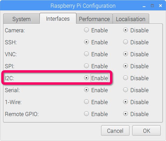
I also recommend that you use a freshly wiped PI with the latest version of Raspbian. It comes pre-loaded with many of the libraries we’ll be using. In order to use I2C, it must be enabled. From the Raspberry Pi main menu click Preferences and then click Raspberry Pi configuration. Select the Interfaces tab and then click to enable I2C. Click OK to close.
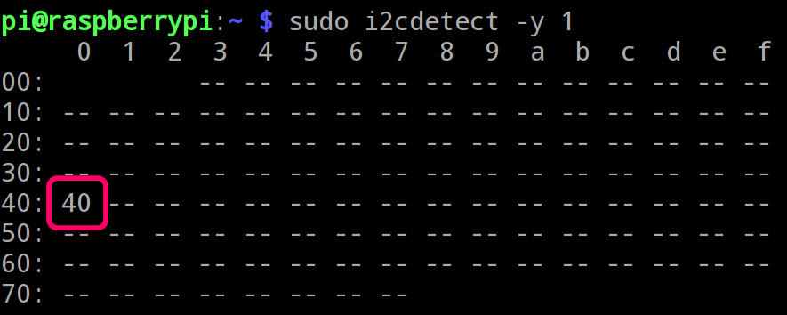
The I2C detect utility can be used to ensure that the INA219 is properly wired. The following table shows a single I2C device at hex address 40 which is the default for the INA219. On older Pi’s the bus parameter might be 0 instead of 1.
You can have 16 INA219’s connected on the same I2C bus as long as each one has a unique slave address. You can change the address by using different connections to pins A0 and/or A1 (see table below which is based on table 1 from the datasheet.)
INA219 Address Pins and Slave Addresses
| A1 | A0 | Slave Address | Hex |
|---|---|---|---|
| GND | GND | 1000000 | 40 |
| GND | VS+ | 1000001 | 41 |
| GND | SDA | 1000010 | 42 |
| GND | SCL | 1000011 | 43 |
| VS+ | GND | 1000100 | 44 |
| VS+ | VS+ | 1000101 | 45 |
| VS+ | SDA | 1000110 | 46 |
| VS+ | SCL | 1000111 | 47 |
| SDA | GND | 1001000 | 48 |
| SDA | VS+ | 1001001 | 49 |
| SDA | SDA | 1001010 | 4A |
| SDA | SCL | 1001011 | 4B |
| SCL | GND | 1001100 | 4C |
| SCL | VS+ | 1001101 | 4D |
| SCL | SDA | 1001110 | 4E |
| SCL | SCL | 1001111 | 4F |
I tested several python libraries for the INA219 and currently the most reliable one is by ChrisB2. Configuring the INA219 optimally is a bit involved and Chris’s library makes it very easy. The pip command to install the library can be copied right from the GitHub readme and then just paste it into a terminal and hit enter. This one command installs the library and all necessary dependencies.
sudo pip install git+git://github.com/chrisb2/pi_ina219.git
The Adafruit python LCD display library will be used to drive the LCD display. It too is quickly installed with sudo pip install adafruit-charlcd. Again this handles the LCD library and all dependencies.
sudo pip install adafruit-charlcd
Here’s the python code:
from time import sleep
from ina219 import INA219
from Adafruit_CharLCD import Adafruit_CharLCD

ina = INA219(shunt_ohms=0.1,
             max_expected_amps = 0.6,
             address=0x40)

ina.configure(voltage_range=ina.RANGE_16V,
              gain=ina.GAIN_AUTO,
              bus_adc=ina.ADC_128SAMP,
              shunt_adc=ina.ADC_128SAMP)

lcd = Adafruit_CharLCD(rs=21, en=20, d4=16, d5=12, d6=7, d7=8,
                       cols=16, lines=2)

try:
    while 1:
        v = ina.voltage()
        i = ina.current()
        p = ina.power()
        lcd.clear()
        lcd.message('{0:0.1f}V {1:0.1f}mA'.format(v, i))
        lcd.message('\n{0:0.1f} Watts'.format(p/1000))
        sleep(1)

except KeyboardInterrupt:
    print ("\nCtrl-C pressed.  Program exiting...")
finally:
    lcd.clear()
The value of shunt_ohms is specified as 0.1 ohms when the INA219 is instantiated. This matches the value of the shunt on the breakout board. The max_expected_amps is set to 0.6. This is the maximum current that you expect to measure. The results will be inaccurate if the actual current draw is higher than this specified amount, but in general, lower values will give you more accurate results. Therefore, you want to pick a value slightly higher than the maximum current of the device being measured. You can always set it high to get an initial ballpark reading and then lower it to get better results. A value of 0.6 provides a safe margin for my indicator lamp which draws about 0.56 A at 12 V. Address specifies hex 40 for the I2C address which can be confirmed with I2C Detect. The default is hex 40 so this parameter is optional.
The configure method sets up the INA219. The voltage_range is set to 16 V. This is the full scale voltage range. The options are 16 V or 32 V. Although the INA219 is limited to 26 V. Since the indicator lamp is rated for 12 V, the lower 16 V option is selected. Gain is used to program the INA219 calibration register in order to maximize the sensor resolution. Valid values are 1, 2, 4 or 8. An auto gain feature removes any guess work. Bus ADC sets the bus analog to digital conversion resolution 9, 10, 11 or 12 bit (higher is better). Multiple sampling is also afforded for improved accuracy at the expense of slower of reads. I don’t care about speed, so I’m using ADC 128 SAMP for 128 samples at 12 bit which will take about 68 milliseconds per reading. Shunt ADC has the same guidelines as the bus ADC but for the shunt. Again I’m using ADC_128 SAMP.
An LCD display is instantiated with the GPIO selections from the schematic above. The main program loop is wrapped in a try statement to catch errors. Variable (V) will store the voltage returned by the voltage method which polls the INA219 for the bus voltage, variable (I) will hold current in mA returned by the current method and variable (P) will hold power in mW returned by the power method. The LCD display is cleared with the clear method. Message displays the bus volts and amps on the first line. Message is used again with \n for the next line on the display. Here watts are shown. P is divided by 1000 to convert milliwatts to watts. The loop pauses for 1 second and repeats.
I received a question regarding inaccurate readings when the INA219 Vin+ and Vin- terminals are disconnected such as if a switch is used to control the device being measured. If the input terminals are not connected then they are considered floating. Voltages are measured relative to the circuit ground. If there is no direct electrical path to that ground the input voltage can have arbitrary readings. One solution is to use a single pole double throw (SPDT) switch. The single pole is connected to Vin+. One throw is connected to ground and the other throw is connected to the supply’s positive line. When on, the switch connects Vin+ to 12 V+. When off, Vin+ goes to ground to ensure zero voltage on the shunt. The switch swaps Vin+ between 12 V+ and ground. Please double check your wiring to make sure your switch doesn’t short 12 V+ to ground.
Here’s another code sample without the LCD display:
from ina219 import INA219, DeviceRangeError
from time import sleep

SHUNT_OHMS = 0.1
MAX_EXPECTED_AMPS = 2.0
ina = INA219(SHUNT_OHMS, MAX_EXPECTED_AMPS)
ina.configure(ina.RANGE_16V)

def read_ina219():
    try:
        print('Bus Voltage: {0:0.2f}V'.format(ina.voltage()))
        print('Bus Current: {0:0.2f}mA'.format(ina.current()))
        print('Power: {0:0.2f}mW'.format(ina.power()))
        print('Shunt Voltage: {0:0.2f}mV\n'.format(ina.shunt_voltage()))
    except DeviceRangeError as e:
        # Current out of device range with specified shunt resister
        print(e)

while 1:
    read_ina219()
    sleep(1)
 NOTE: Chris’s INA219 library requires the logging library which is part of the MicroPython Lib repository.