This project involves the creation of what I’ll call a ‘Toddler’s Interactive Adventure Pod’—an imaginative play space designed to spark joy and wonder in the heart of a courageous little boy. My 2-year-old nephew has faced incredible challenges, including open heart surgery, this project is more than just a gift; it’s a testament to resilience and the magic of childhood exploration. This writeup explores the nuts and bolts of the construction including woodworking, electronics and programming.
Table of Contents
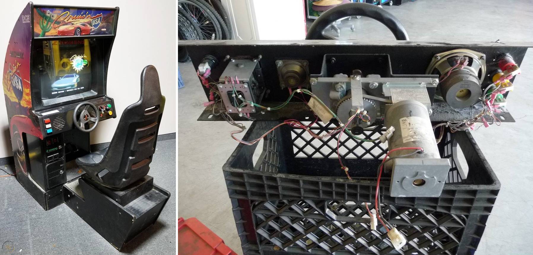
Long time viewers of the channel know I have a passion for building and repairing video arcade machines and arcade controls. So that’s where I started with my quest to make a gift for my nephew’s second birthday party because he loves cars and anything with switches or buttons. I found a local arcade operator selling a large assortment of driving controls. They were somewhat abused but nothing that couldn’t be repaired. I selected a control panel from the classic 1994 arcade game Cruis’N USA. I got a great deal considering vintage controls tend sell for a lot of money and this control panel was complete with a force feedback motor, wiring harness and all the switches. When my nephews a little older I figure we could turn it into a proper arcade machine.
The Build
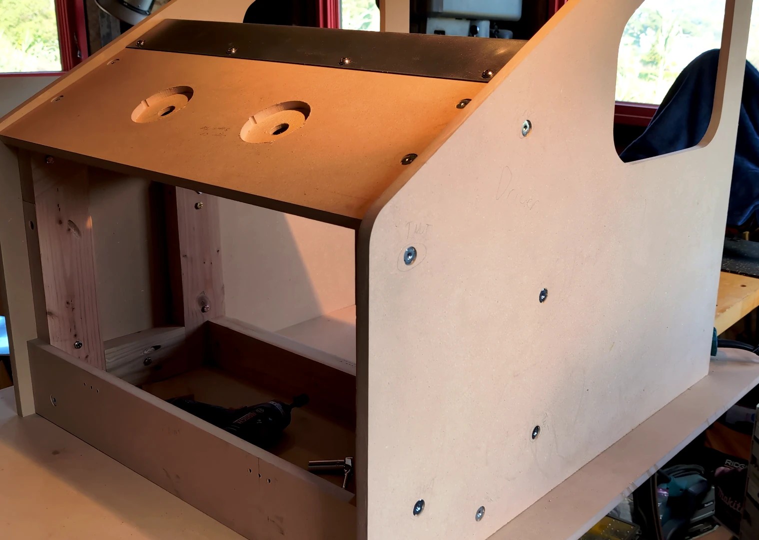
I designed the Pod’s in Sketchup. Here’s the frame.
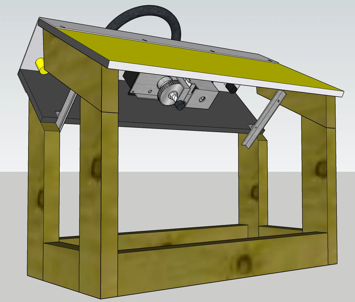
The control panel is mounted on the wood frame which is constructed of 2×4’s and 5/8-inch MDF. I stripped off the panel’s black paint and the bare steel looked really good, so I just applied food-grade wax to prevent the metal from rusting. The panel is mounted to the MDF with 5/16-inch stainless steel screws and T-nuts. The wood is just screwed together. Pocket screws are used for some of the butt joints. I added ¾-inch aluminum angle between the top and bottom of the control panel to enhance rigidity. I drilled holes for grade-8 quarter inch bolts which will be used to secure the removable outer panels.
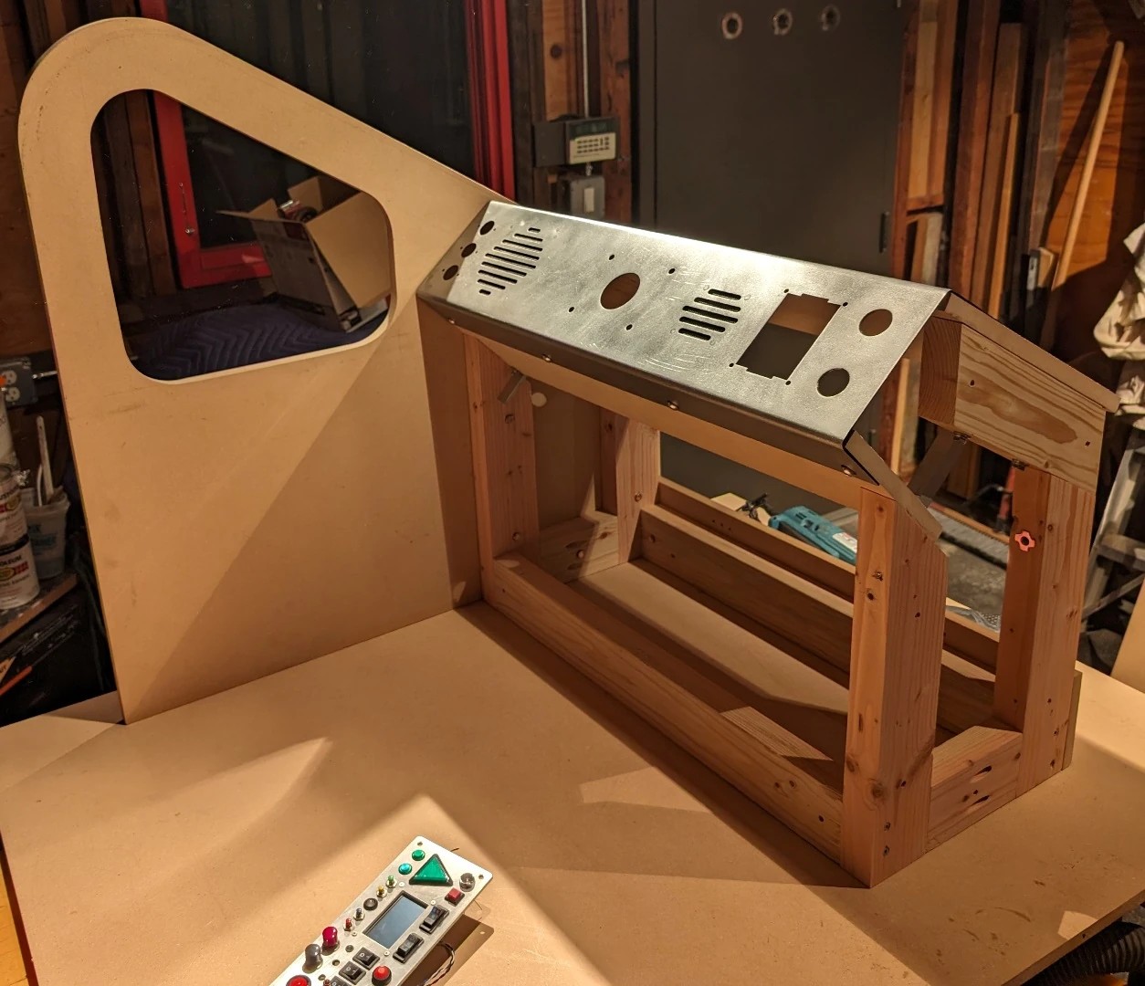
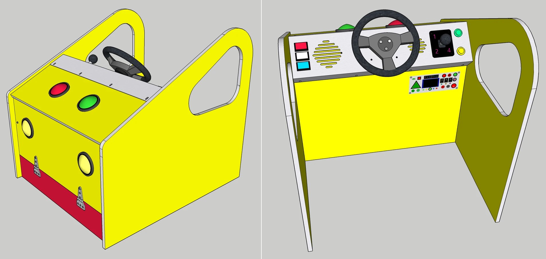
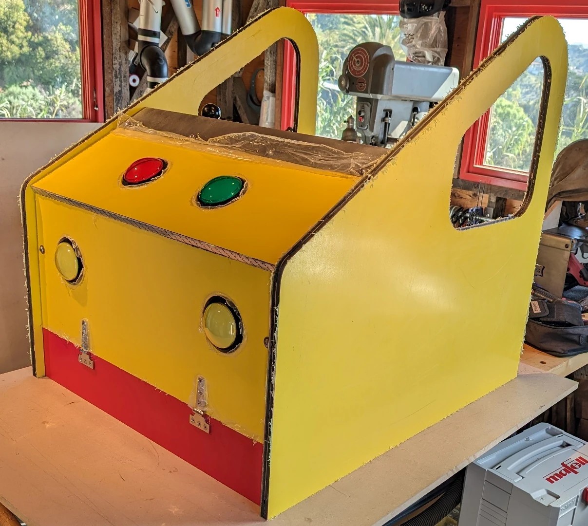
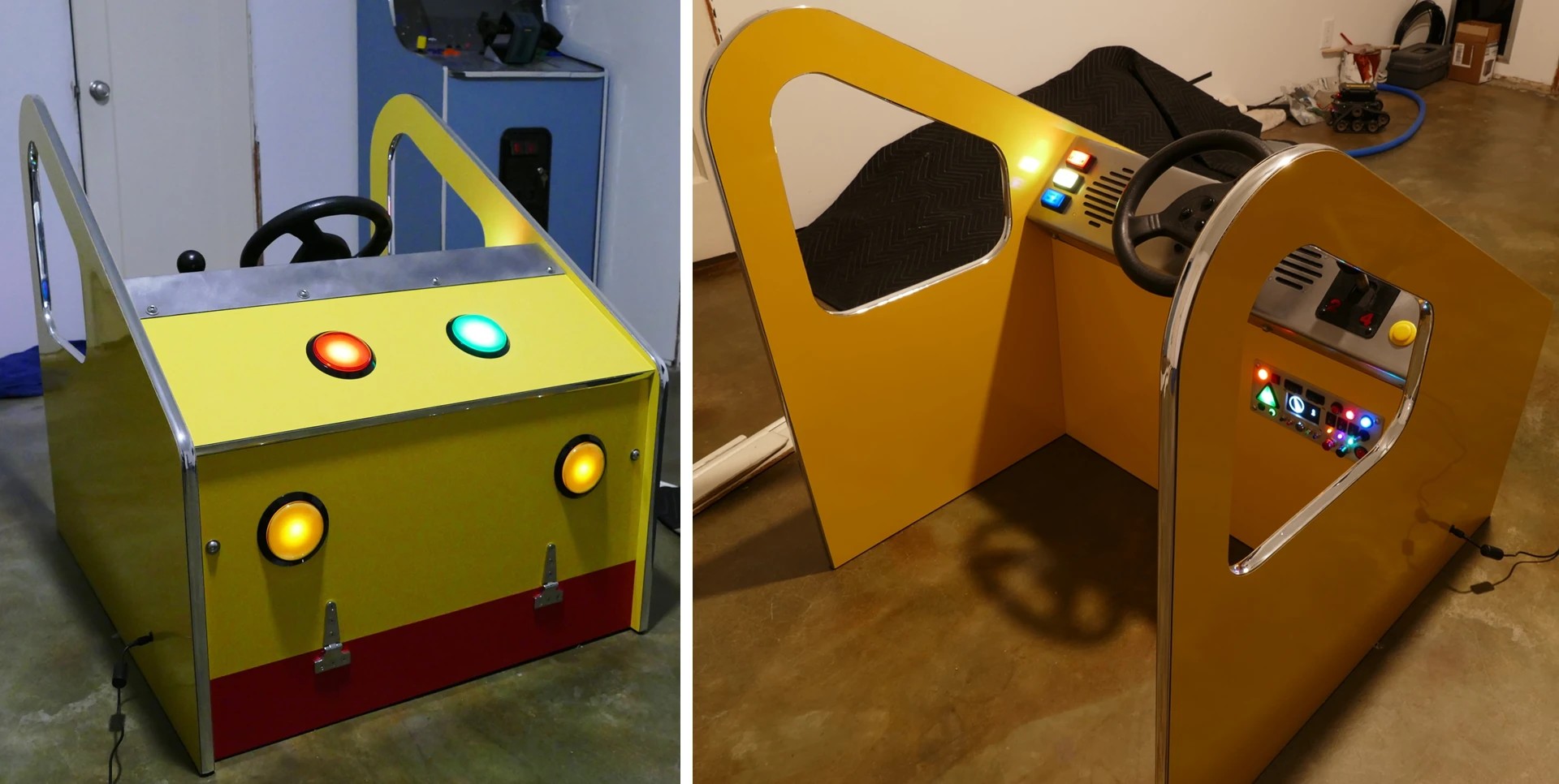
Here’s the full Sketchup model of the pod. The front panel is hinged to allow for maintenance. Large 100mm illuminated pushbuttons are used for the yellow headlights and the red and green strobes on the hood. Window-like openings have been incorporated into the side panels to evoke an automotive aesthetic. The pod is about 29.5 inches wide (75 centimeters), 34.5 inches long (88 centimeters), and 31 inches tall (79 centimeters).
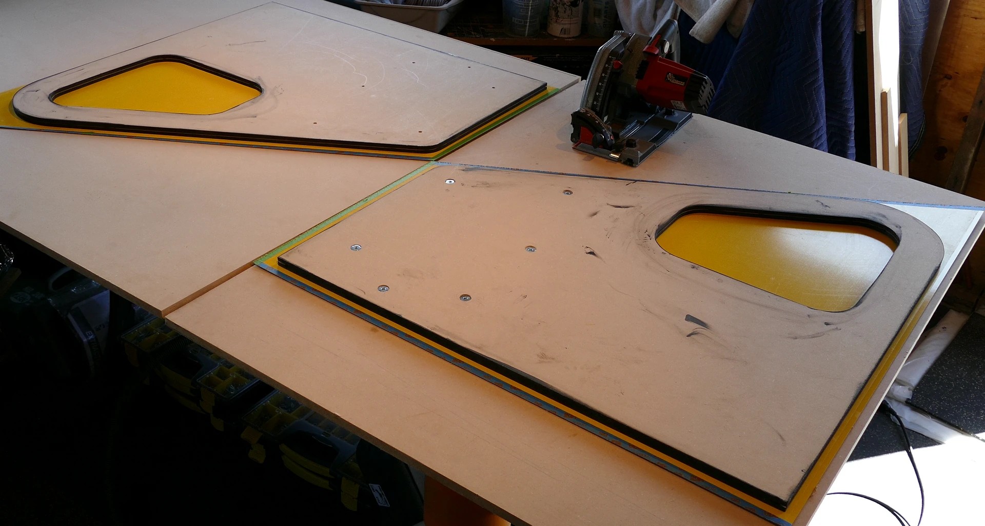
I routed holes on the hood so the 100mm illuminated pushbuttons will sit flush. The outer panels are mounted with T-nuts to afford easy disassembly. The T-nuts are slightly recessed. This will ensure a smooth finish for the laminate which will cover all the exposed MDF.
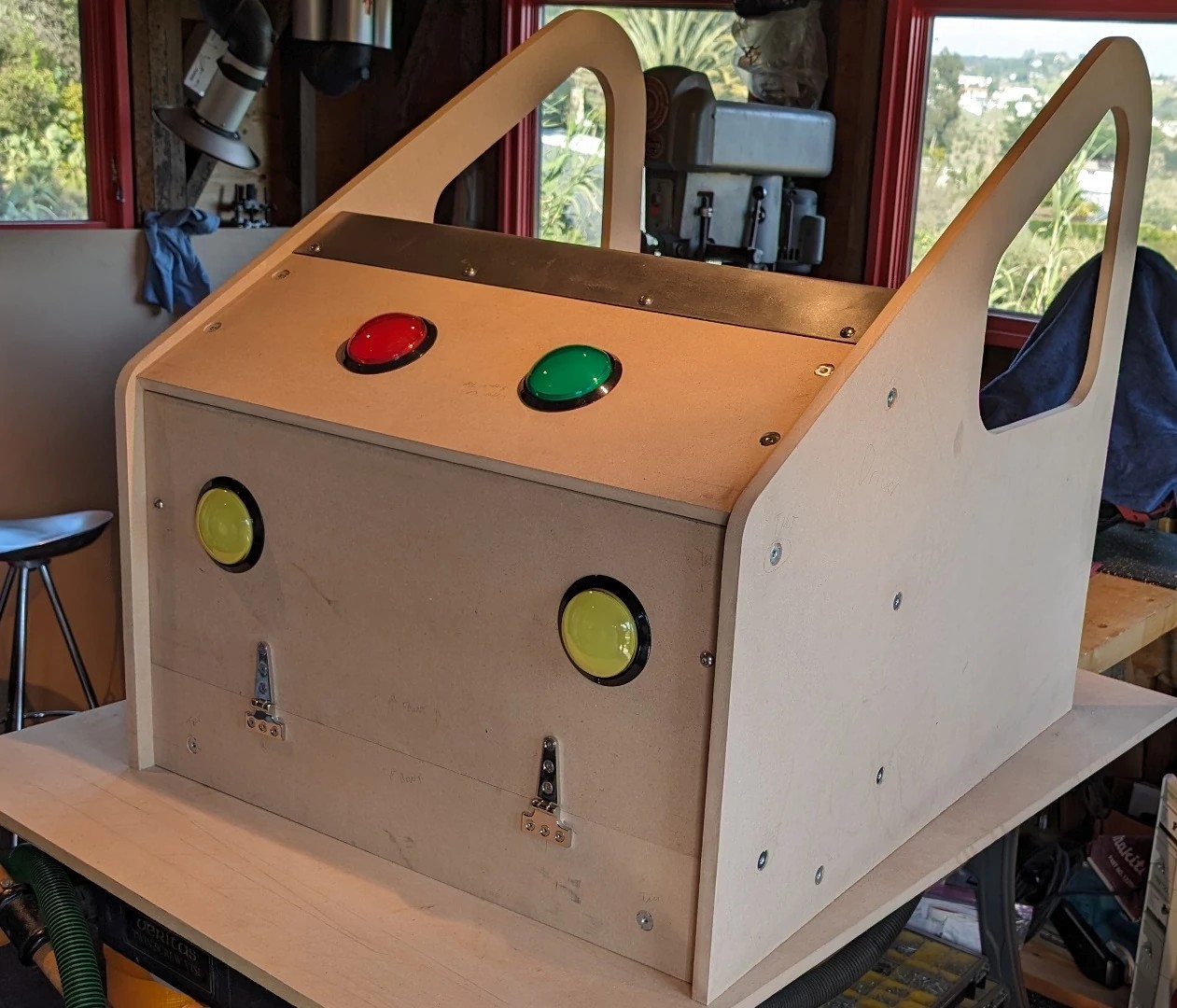
The pod is all ready for laminate. The chrome hinges are fitted. The 100 mm illuminated pushbuttons are mounted.
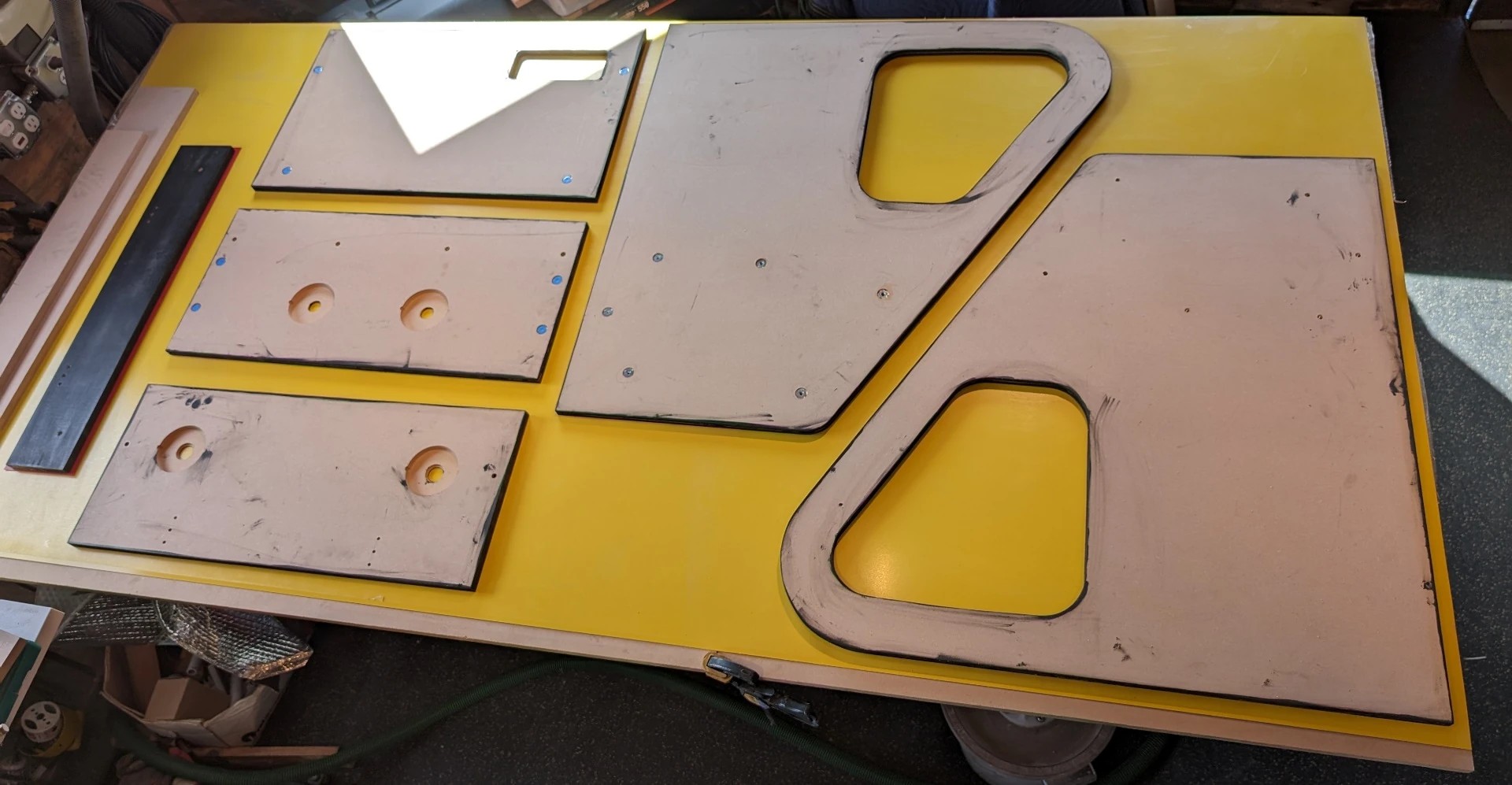
Here are the panels laid out on high pressure laminate. The color is High Gloss Primary Yellow. The sheets are 97 x 49 inches (About 2-1/2 x 1-1/4 meters).
The laminate is cut using a track saw with a 56-tooth carbide tipped laminate cutting blade with a thin kerf of 1.8mm (a little over a 1/16 of inch). Masking tape is placed along the cuts to reduce the chance of splintering.
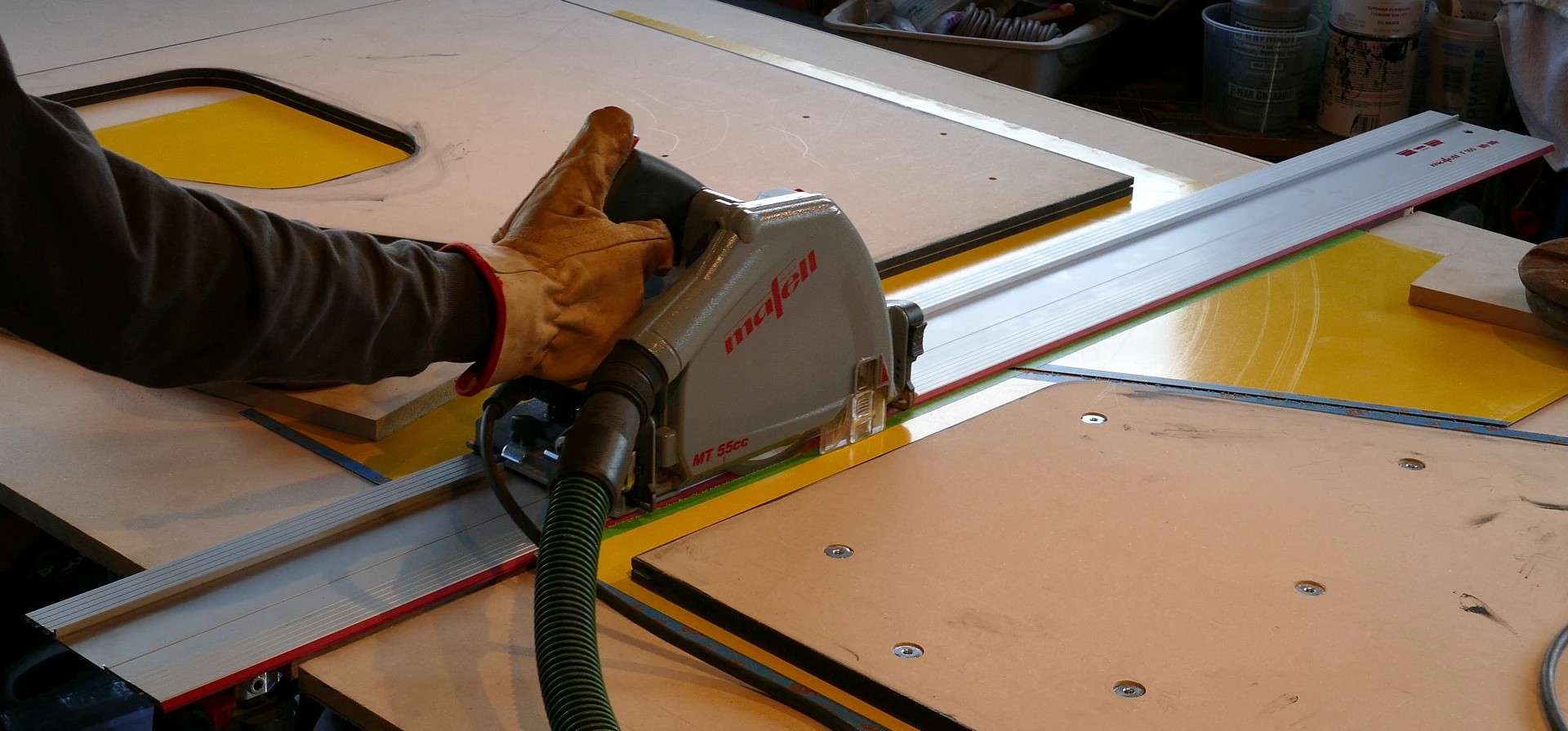
Some sites recommend cutting with the laminate facing down but all my cuts came out clean. Furthermore, I leave at least a 1-inch margin around the laminate to make it easier to glue. The excess will be removed with a router and flush trim bit.
Here’s the pod with the laminate installed. Unfortunately, I lost the footage of applying the laminate with contact cement and the flush routing, but there are lots of laminate tutorials on YouTube. The frayed material on the edges is just the protective plastic film which I’ll remove at the very end.
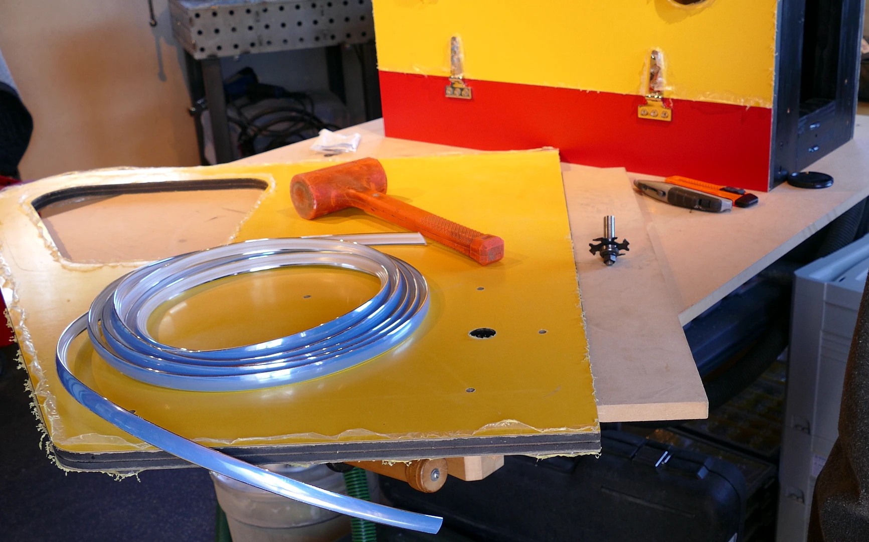
Chrome T-molding is installed to clean up the edges. It’s 5/8 inch thick (15.9mm). A slot cutter router bit is used to cut a 1/16-inch (1.6 mm) channel in the center of the edges to accept the T-molding. To install the T-molding you just line up one end with the bottom edge which won’t have any T-molding because it’ll be on the floor. It’s hard to remove T-molding without damaging the MDF channel so take your time. Then just gently tap it in with a soft mallet. You don’t want to use hammer with a hard surface because you can chip the chrome coating. The T-molding should be held very tightly by the channel but if you make a mistake or it comes loose, you can use some hot glue or wood glue to hold it in place.
Here’s the completed pod with the T-molding installed on all the exposed edges including the insides of the windows. The photos are a bit out of sequence as you can see by all the functioning illuminated switches. Most of the animated lighting effects are being controlled in software by a Raspberry Pi Pico. This will be discussed in detail but first I’ll focus on the electronics and wiring, starting with the secondary control panel located under the Cruis’N USA panel.
Electronics
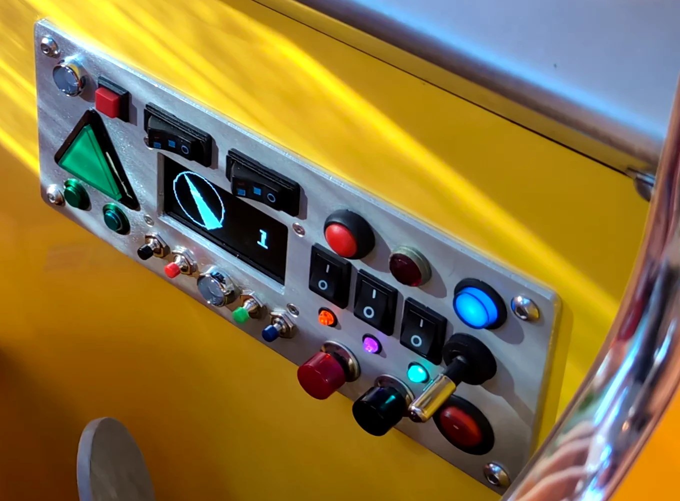
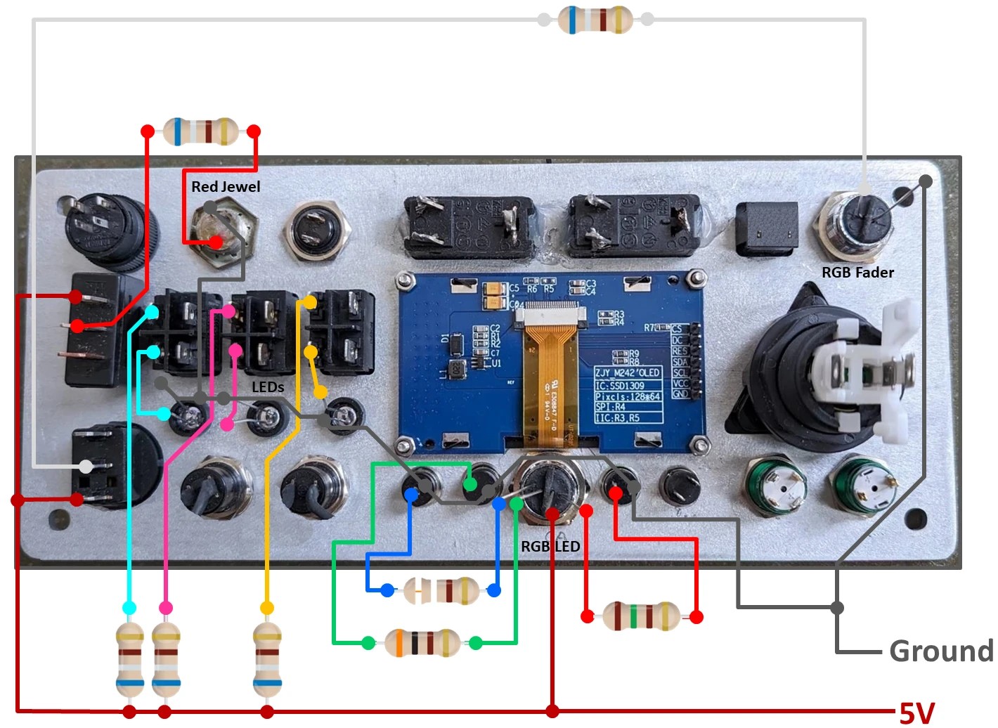
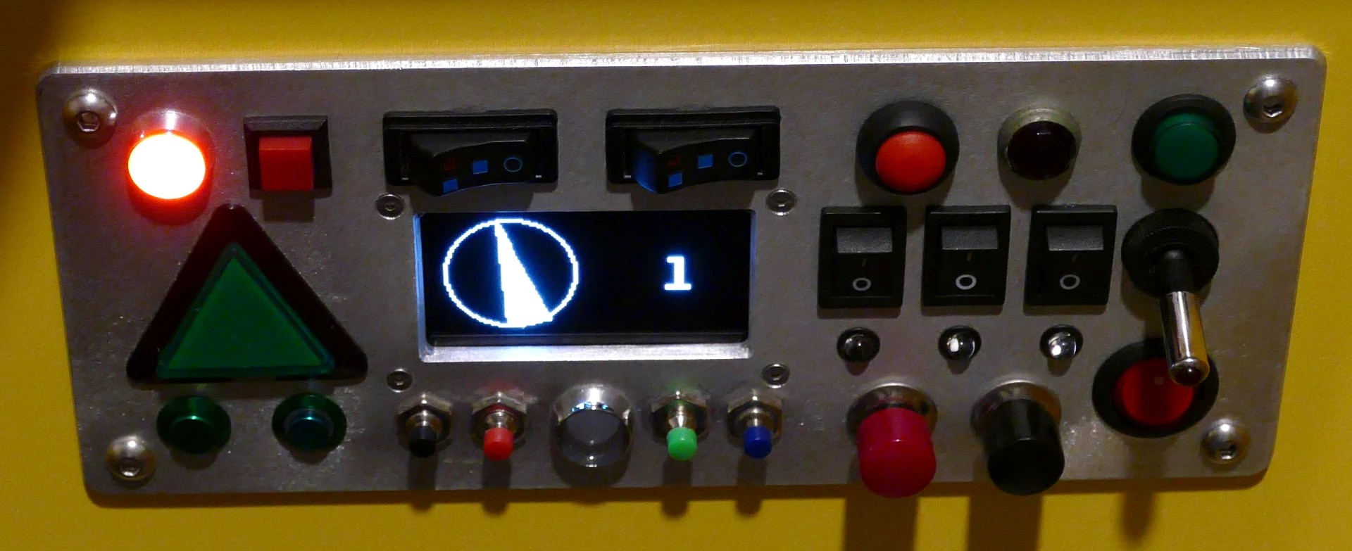
This control panel has a toggle switch, 12 pushbuttons, and 6 rocker switches. Two of the rocker switches are 3-position. There are three 5mm LEDs in orange, magenta and turquoise, 1 vintage jeweled red pilot, 2 8mm RGB LEDs, one is auto-fading, 3 of the pushbuttons are illuminated and there’s a white OLED display.
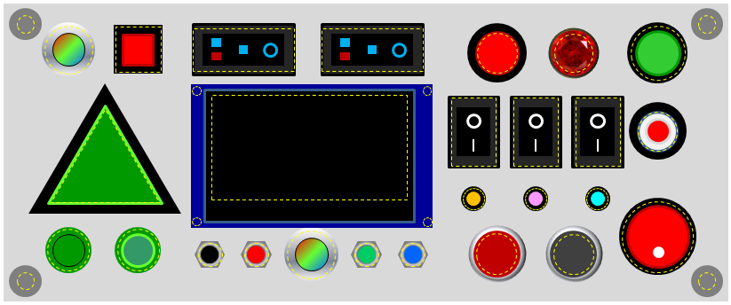
I designed the control panel in PowerPoint because I give a lot of presentations. There’s probably better software, but it’s works, it’s easy, it’s in color, it’s to scale, it’s easy to overlay the hole cutouts and when the layout’s finalized I was able to write a simple Visual Basic macro called ExtractShapeInfo to export the coordinates and dimensions into my CNC software. The code is available in the downloads below.
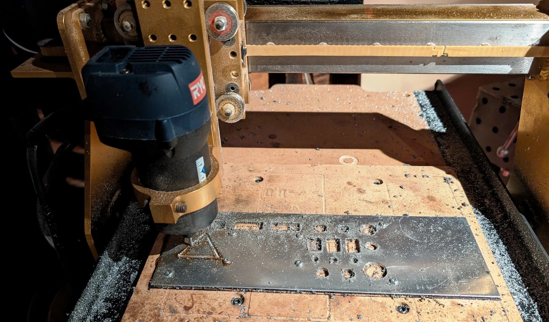
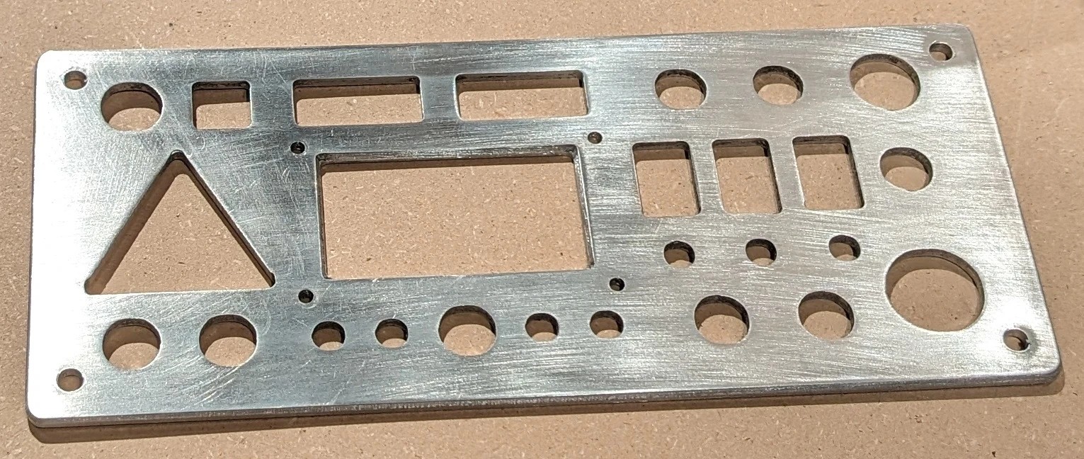
Here’s my Romaxx CNC router cutting out the secondary control panel from a sheet of aluminum 1/8” thick (about 3MM). It makes easy work of the switch rectangles, the triangular push button, the display cutout, bevels and the rounded corners.
Here’s the cut panel. I used a random orbit sander with high grit paper to get a clean brushed finish.
Here’s the back of the panel with the switches, pushbuttons, LEDs and the display installed. The discrete LEDs are all hard wired which just means they are controlled independently of the Raspberry Pi Pico which will control everything else. The cathodes of the 5MM LEDs, the RGB fader and the red jeweled LED are connected to ground along with 3 of the mini pushbuttons. The 8mm RGB LED on the bottom has a common anode which is connected to 5V along with a pin from each of the large toggle switches. The normally open pin of the top toggle switch is connected to the anode of the red jeweled LED in series with a 690 ohm resistor. Flipping the switch allows power to flow and illuminates the LED. The normally open pin of the bottom toggle switch is connected to the RGB fader in series with a 690 ohm resistor. This LED has a built-in circuit that automatically fades the LED through the colors of the rainbow. The bottom 8mm RGB LED has its red, green and blue cathodes wired to the red, green and blue mini pushbuttons in series with a 150 ohm resistor, a 300 ohm resistor and a 90 ohm resistor respectively. The 3 remaining hardwired 5mm LED anodes are wired to the mini rocker switches. The other ends of the switches are wired to 5V with 690 ohm resistors in series.
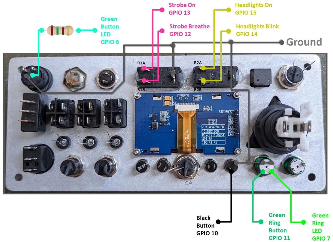
The remaining 2 pushbuttons, 2 rocker switches and 2 illuminated switch’s LEDs are controlled by the Pico. Each pushbutton and switch has a pole connected to ground along with the button LED cathodes. The large round green illuminated pushbutton has its anode connected to GPIO 6 on the Pico with a 150 ohm resistor in series. When the pin goes high the button will light up. The anode of the green metal pushbutton’s ring LED is connected to GPIO 7. This button has a built-in resistor so it can be wired directly to the Pico. The normally open poles of the black mini pushbutton and the green metal ring pushbutton are connected to GPIO 10 and 11 respectively. When they are pressed the GPIO pins will be pulled low to ground. The two 3-position rockers are connected to GPIO 12 through 15. They will be used to set the mode of the headlights to off, on or blink and the red and green strobe lights to off, on or breathe.
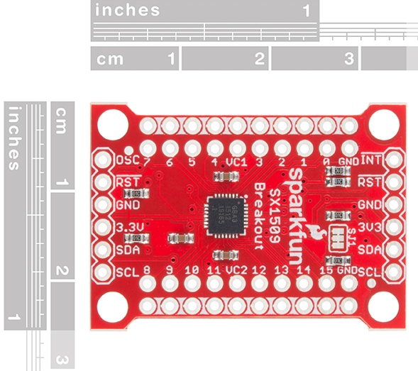
The Raspberry Pi Pico has 26 exposed GPIO pins but this project will require 48 GPIO pins to control all the switches, lights and peripherals. Therefore, I’m using a SparkFun SX1509 I2C I/O expander. The SX1509 provides 16 level-shifting bi-directional GPIO pins with programmable pull-up or pull-down resistors. You may be thinking that these 16 GPIOs combined with the Pico’s 26 GPIO pins will still only provide 42 of necessary 48 required pins. However, the SX1509 has an on chip keypad scanning engine that supports up to an 8×8 matrix of 64 inputs. Therefore, I can use half of the pins for a 4×4 matrix of 16 inputs and still have 8 inputs left over for LEDs. This is equivalent to 24 GPIO pins. The SX1509 has a built-in LED driver which offers PWM, blinking and a special effect called breathing which smoothly fades an LED on and off. Furthermore, each GPIO pin can sink 15 mA of current with no cumulative limit. The SX1509 operates between 1.2 and 3.6 volts so it’s a great match for the Pico.
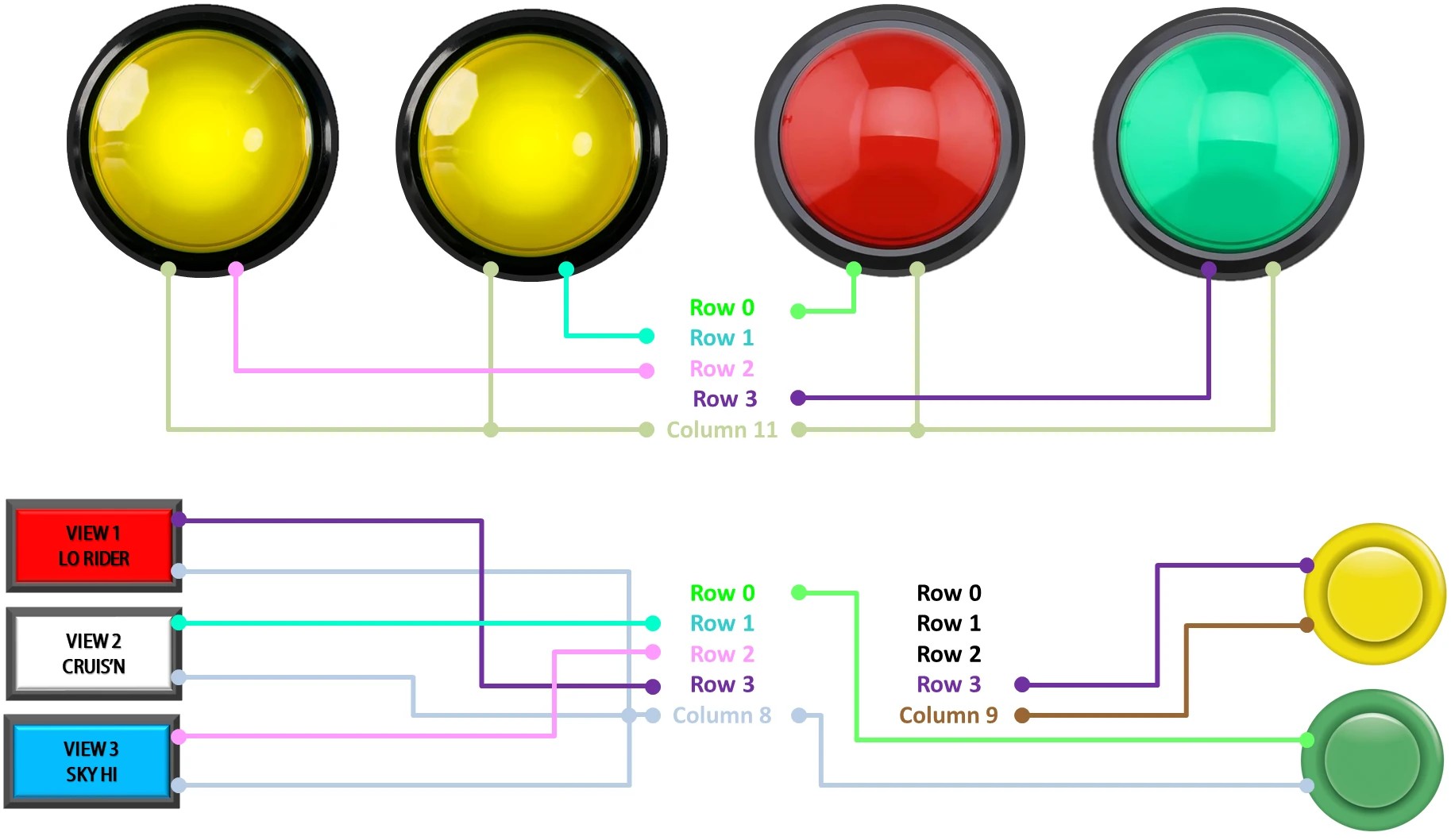
You might assume that a keypad engine needs a matrix keypad, but you can achieve similar functionality using discrete inputs. For instance, instead of a common ground, four of the control panel pushbutton switches have one pole connected to a common column 10 while the other poles are wired to the 4 individual keypad rows 0 to 3. This setup mimics the row and column structure of a matrix keypad, allowing the keypad engine to function correctly with individual pushbutton switches. The 3 remaining pushbuttons have a pole connected to column 9 and the other poles to rows 0 – 2. The unused row 3 will be reclaimed later by the arcade control panel.
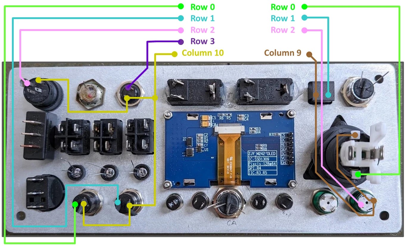
The Pod has four 100mm illuminated pushbuttons mounted on the hood and grill. They act as lights and buttons. The Cruis’N USA panel has 3 illuminated rectangular pushbuttons (red, white and blue) and 2 standard arcade buttons (yellow and green). The yellow arcade button is connected to the expanders remaining row 3 on column 9. The green button and 3 rectangular buttons are connected to Rows 0 to 3 on Column 8. The four 100mm pushbutton inputs are connected to rows 0 to 3 on column 11. That uses up all 16 inputs on the keypad matrix.
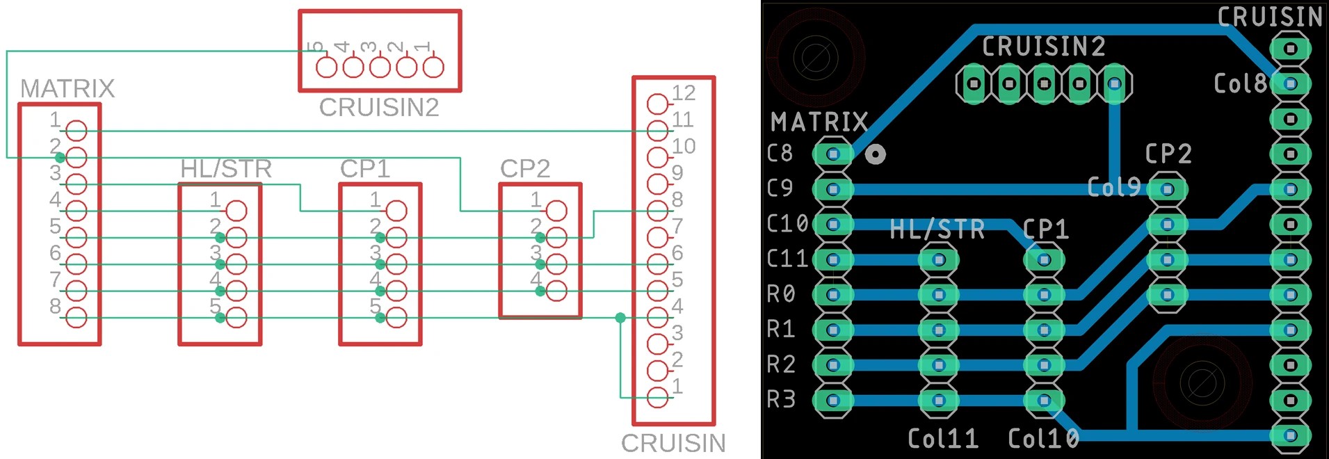
In order to simplify the wiring I created a small keypad matrix PCB. It has the 2 inputs for the Cruis’N USA control panel so I could reuse the existing 12 pin and 5 pin connectors. I want to keep the harness original to simplify any future conversion back to an arcade cabinet. The 3 other connectors are for the other 3 columns of inputs. There is a single 8 pin output for the 4 by 4 matrix on the SX1509 expander.
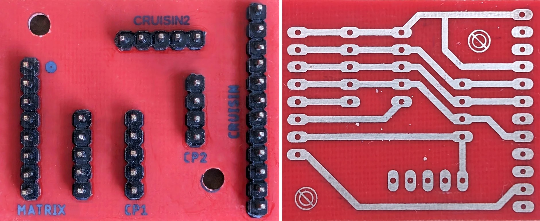
I etched the board myself using muriatic acid and hydrogen peroxide. Here are my etching notes.
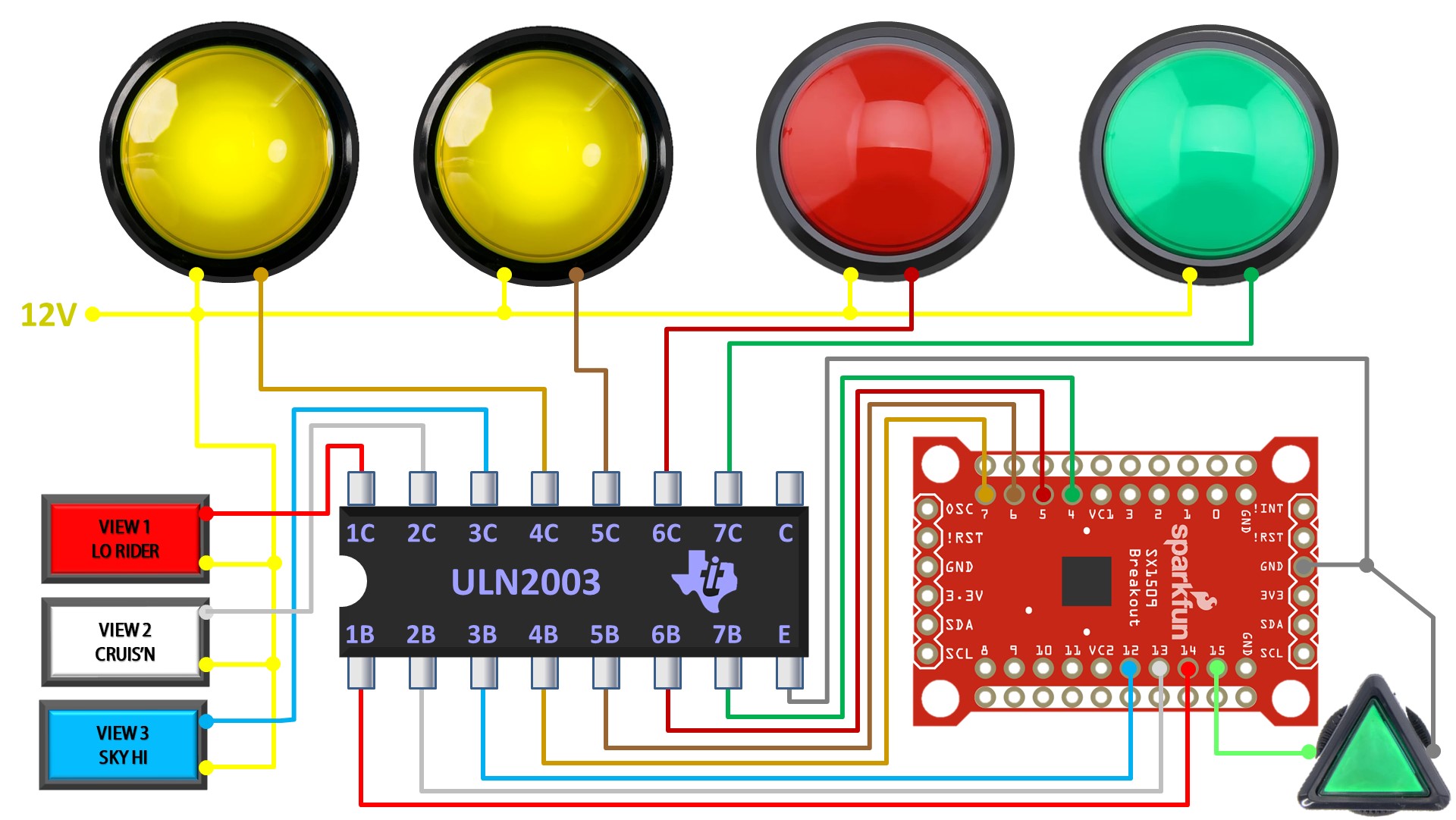
The LED bulbs in the arcade pushbuttons are all 12 volts so they cannot be powered directly from GPIO pins. Typically, you could use MOSFETs or transistors to drive the LEDs, but a more elegant solution is the ULN2003 which is an integrated circuit featuring seven Darlington transistor pairs with built-in flyback diodes, designed for driving high-current loads like motors, relays, and LEDs directly from digital logic circuits. It’s inexpensive and simplifies the design by reducing the number of parts.
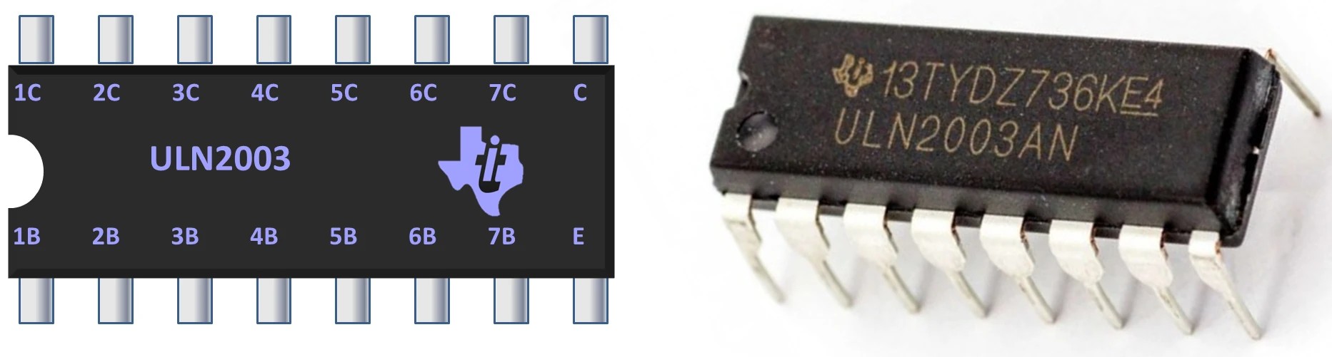
The ground pin on the ULN2003 is connected to a ground pin on the SX1509. The anodes of each LED bulb in the rectangular pushbuttons are connected directly to 12 volts. The expander’s pins 12, 13, and 14 are linked to the ULN2003’s pins 1B, 2B, and 3B, respectively. The corresponding pins 1C, 2C, and 3C on the ULN2003 are then connected to the cathodes of the pushbuttons. When a pin on the expander is set high, then the associated pin on the ULN2003 will sink current and light up the LED bulb. 12 volts is also connected to the anodes of the 100mm pushbutton LEDs. Then pins 4, 5, 6 and 7 on the expander are connected to pins 7b, 6b, 5b and 4b on the ULN2003 respectively, and the 4 corresponding C pins are wired to the cathodes of the pushbuttons. Pin 15 on the expander is wired directly to the triangular arcade pushbutton LED anode. I replaced this bulb with a more efficient LED so it can be run directly at 3.3 volts. The cathode goes to ground. When the expander pin goes high it will source current to and illuminate the LED. At 3.3 volts the LED bulb does not require a resistor and won’t exceed the 8mA maximum per pin source limit of the expander.
The last two controls are the analog steering wheel and the 4-speed gear shifter. One terminal of the wheel’s potentiometer is connected to 3.3 volts on the Pico. The pot’s wiper is connected to GPIO 26 which is one of the Pico’s 3 ADC pins. The third terminal on the pot is connected to ground. Turning the steering wheel will vary the voltage on the ADC pin between approximately 0 and 3.3 volts. One pole from each of the gear shifter’s 4 microswitches is connected to GPIO pins 16 through 19. The other poles are connected to ground. When the shifter changes gear the connected pin on the Pico will be pulled low.
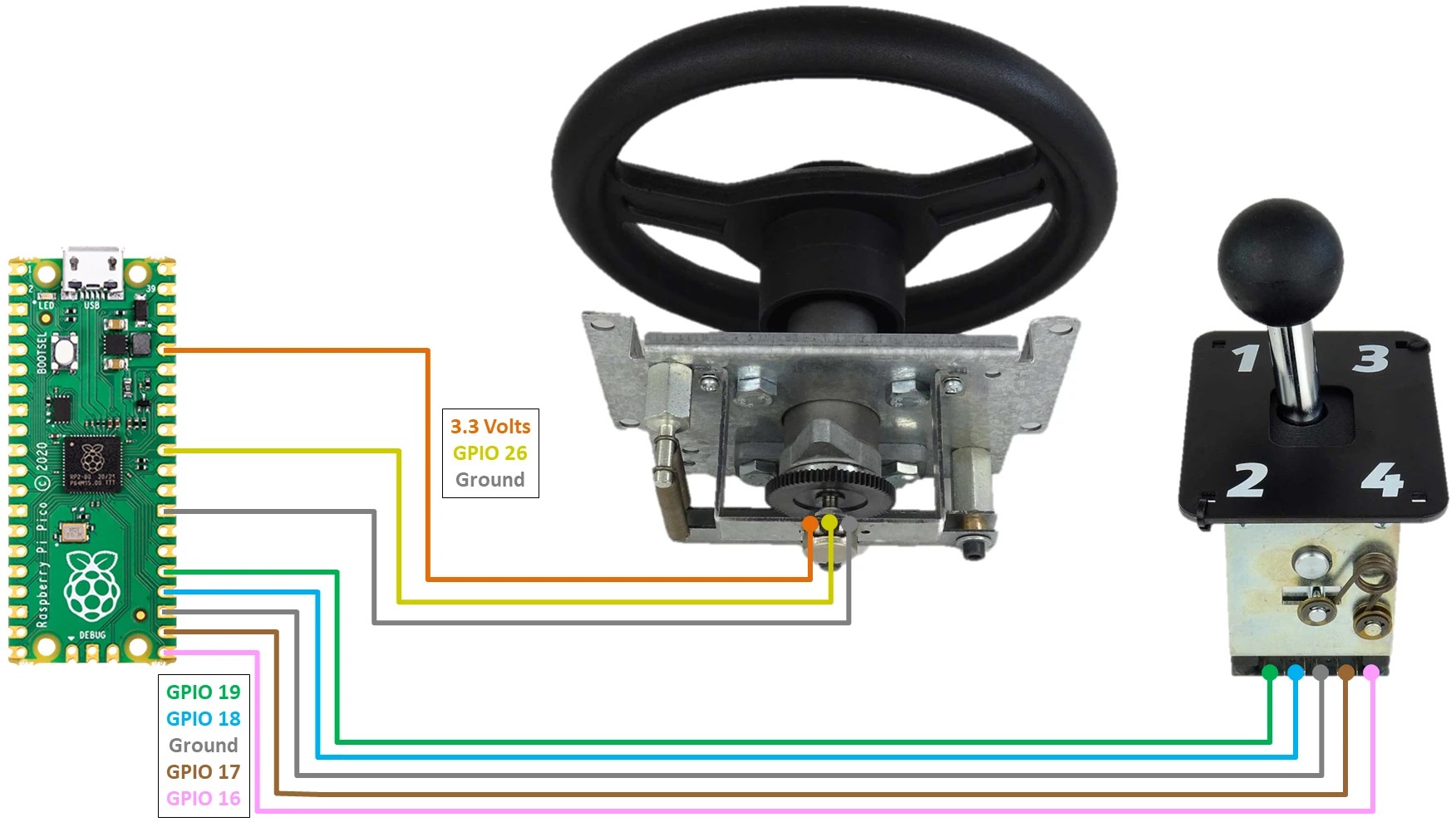
Since only 1 gear can be selected at a time it would be possible to save 1 GPIO pin by using OR gates to convert the 4 gear positions plus neutral to a binary number zero to five which only requires 3 bits or 3 GPIO pins, but the added complexity would only be worth it if I ran out of GPIO pins.
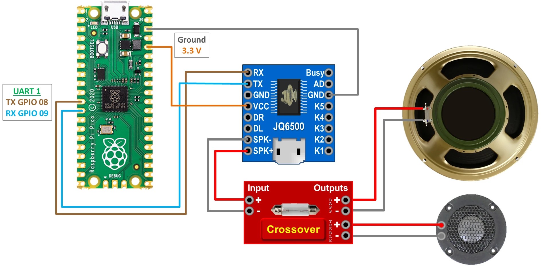
The Cruis’N USA control panel came with a woofer and a tweeter which I replaced because they were in bad shape. The control panel also came with a crossover to connect both speakers to an audio source. A JQ6500 MP3 module will be used to drive the speakers and play sound effects. It’s the same board I used in my ESP32 Touch and Sound Tutorial. The board is controlled by a serial interface. GPIO 8 on the Pico which is UART 1 TX is connected to the RX pin on the JQ6500. GPIO 9 RX is connected to TX. A 3.3 volt pin is connected to VCC, and the grounds are connected. The crossover splits the audio signal into two frequency bands, directing high frequencies to the tweeter and low frequencies to the woofer. The speaker plus and minus pins on the JQ6500 are connected to their corresponding input pins on the crossover. The crossover outputs are wired to the tweeter and the woofer being careful to match the polarity.
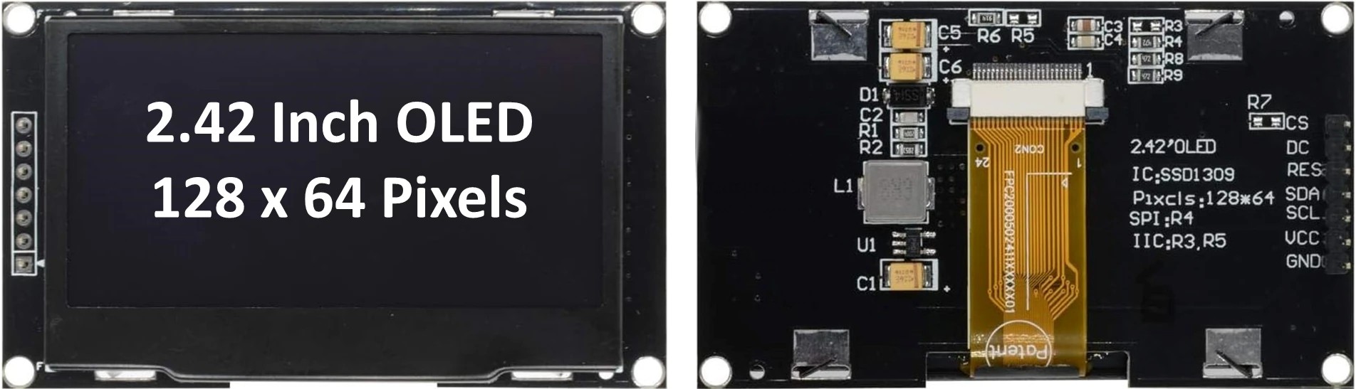
The last electronic component is the SSD1309 OLED display on the lower control panel. This is the same 2.42-inch monochrome display I used in my CallerID project. It has excellent contrast and a wide viewing area. It’s only 128 by 64 pixels but that should be plenty for this project. It runs at 3.3 volts so it can be powered from the Pico. It can communicate by either I2C or SPI. However, SPI will give better performance especially for any animated graphics.
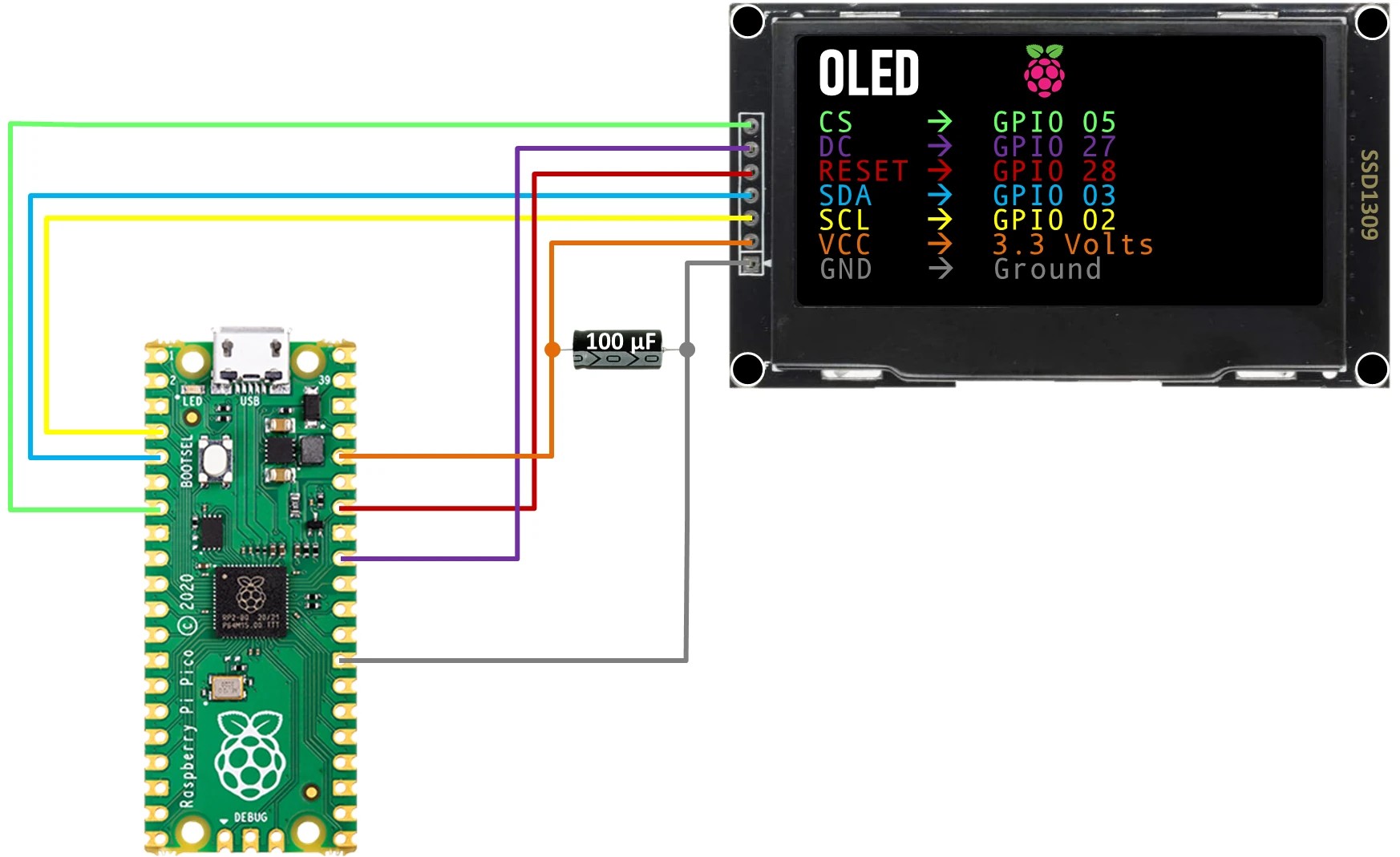
Wiring the display to the Pico is easy. The display’s CS pin goes to GPIO 5 on the Pico. DC goes to GPIO 27. Reset goes to GPIO 28. SDA goes to GPIO 3. SCL goes to GPIO 2. VCC goes to 3.3 volts. The grounds are connected and a 100-microfarad capacitor is placed between VCC and ground to prevent brownouts on the Pico.
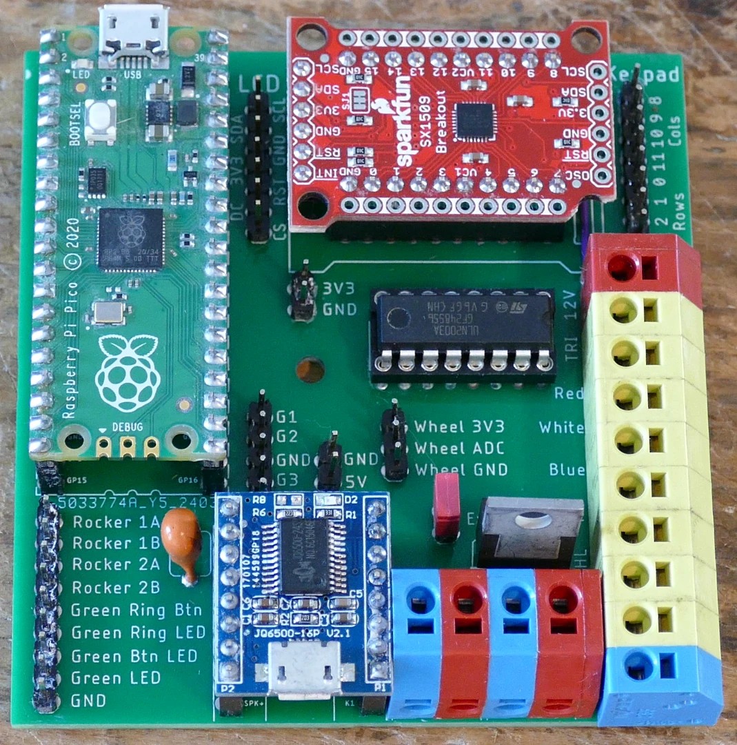
There’s a lot of wiring between the Pico, the MP3 module, the I/O expander, the transistor array IC, the display and all the controls so I designed a main PCB to simplify the wiring. Here’s the schematic.
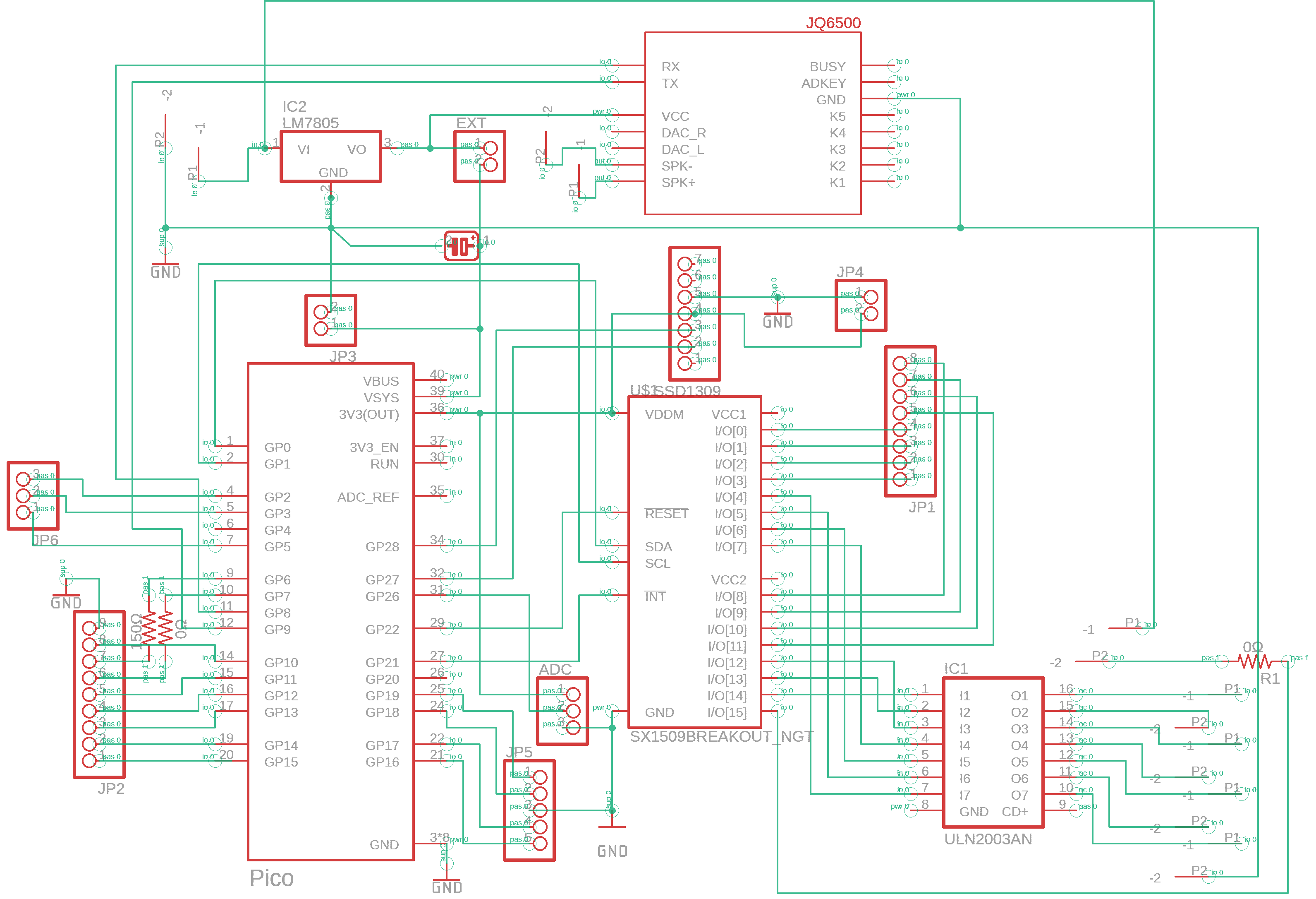
Here’s the board.
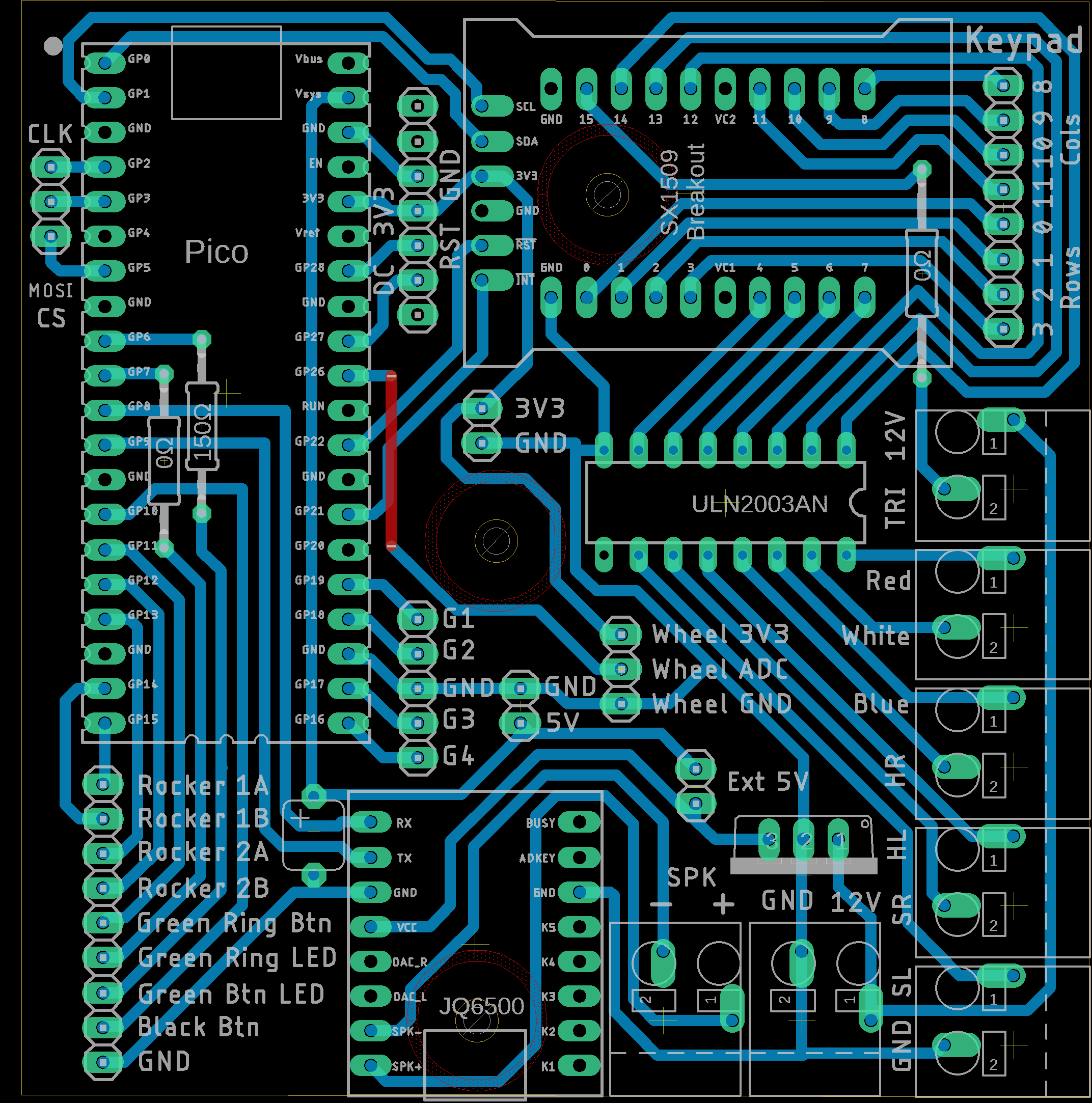
It will hold all the breakout boards, the ULN2003 IC, a 5 volt regulator and headers and terminals for all the inputs, lights and display. Here’s the PCB. I outsourced the fabrication because I didn’t feel like drilling over 150 holes and there’s a lot of small text which really isn’t suitable for the toner transfer method.
Software
I wrote 3 MicroPython driver libraries that are used in this project. The code is available on my GitHub site along with many examples:
The main program is called car.py. Here’s the import section. Array is imported to provide polygon coordinates which have to be unsigned short integers. GC is Python’s garbage collector, which can be manually invoked to free up memory. My JQ6500 MP3 driver is imported. From machine ADC is used for the analog input, I2C for communication with the expander, Pin for control of GPIO pins and SPI to talk to the OLED display. From math a few trigonometric functions are imported to calculate polygon coordinates. From Micropython, const is imported to declare constants which helps optimize memory. My SSD1309 OLED display library is imported. My SX1509 I/O expander library is imported. From time, sleep_ms is imported for short delays, and my xglcd_font library is imported to draw text on the display.
from array import array
import gc
from jq6500 import Player
from machine import ADC, I2C, Pin, SPI  # type: ignore
from math import cos, radians, sin
from micropython import const  # type: ignore
from ssd1309 import Display
from sx1509 import Expander, PinModes
from time import sleep_ms
from xglcd_font import XglcdFont
A little class called LightMode acts as an enum to define the 3 states of the 100mm LEDs, either off, on or blink.
class LightMode:
    OFF = 0  # Lights off
    ON = 1  # Lights on
    BLINK = 2  # Lights blink
The main car class handles all input and output functionality for the pod. Several constants are defined. The OLED display will have a triangular gauge indicating the steering wheel position as defined by radius, base, height, number of positions, angle span, ADC GPIO pin and a hysteresis threshold to smooth transitions between positions. The GPIO pins for the 2 pushbuttons not on the expander are defined. The 4 GPIO pins for the gear shifter are defined. There are 4 GPIO pins for the two 3-position rockers that control the 100mm LEDs. There are 8 GPIO pins for the 8 LED’s controlled by the I/O expander and 2 GPIO pins for the 2 LEDs controlled directly by the Pico. GPIOs for the display’s SPI bus CS, DC and Reset are defined. Constants are set for the keypad engine, rows, columns, sleep time, scan time, debounce time and cycles before a release is registered.
class Car(object):
    """Car controls."""

    # Constants
    CIRCLE_RADIUS = const(28)  # Circle encompassing wheel indicator
    TRIANGLE_BASE = const(20)  # Triangle wheel indicator base
    TRIANGLE_HEIGHT = const(27)  # Triangle wheel indicator height
    TRI_POSITIONS = const(17)  # Number of wheel indicator positions
    ANGLE_SPAN = 225 / (TRI_POSITIONS - 1)  # Wheel indicator angle span
    WHEEL_ADC = const(26)  # Steering wheel potentiometer ADC pin
    HYSTERESIS_THRESHOLD = const(1500)  # Wheel analog hysteresis threshold
    BLACK_MINI = const(10)  # Black miniature pushbutton (not on expander)
    GREEN_RING = const(11)  # Green metal ring pushbutton (not on expander)
    G1, G2, G3, G4 = const(19), const(18), const(17), const(16)  # Shifter pins
    ROCKER_HL1, ROCKER_HL2 = const(15), const(14)  # Headlights rockers
    ROCKER_STROBE1, ROCKER_STROBE2 = const(13), const(12)  # Strobe rockers
    HL1_LED, HL2_LED = const(6), const(7)  # Headlight LED expander GPIOs
    STROBE1_LED, STROBE2_LED = const(4), const(5)  # Strobe LED expander GPIOs
    GREEN_TRI_LED = const(15)  # Green triangular pushbutton LED expander GPIO
    LO_RIDER_LED = const(14)  # Lo Rider pushbutton LED expander GPIO
    CRUISIN_LED = const(13)  # Cruis'n pushbutton LED expander GPIO
    SKY_HI_LED = const(12)  # Sky Hi pushbutton LED expander GPIO
    GREEN_ILL_LED = const(6)  # Green illuminated pushbutton LED GPIO
    GREEN_METAL_LED = const(7)  # Green metal pushbutton ring LED GPIO
    CS = const(5)  # Display chip select pin
    DC = const(27)  # Display data/command mode pin
    RESET = const(28)  # Display reset pin
    KEY_ROWS = const(4)  # Number of rows in the keypad
    KEY_COLS = const(4)  # Number of columns in the keypad
    SLEEP_TIME = const(256)  # Time in ms for keypad low-current sleep mode
    SCAN_TIME = const(30)  # Scan time in ms devoted to each matrix row
    DEBOUNCE_TIME = const(15)  # Keypad debounce time in ms
    MAX_RELEASE = const(5)  # Number of cycles before a button can be released
KEY_MAP is a 2D list where each item represents the name of the button in the keypad matrix, organized by row and column.
    # Map of buttons to rows / columns
    KEY_MAP = [
        ['green_arcade', 'red_square', 'red_rs', 'red_strobe'],
        ['cruisn', 'green_tri', 'black_rs', 'hl_right'],
        ['sky_hi', 'green_metal', 'green_ill', 'hl_left'],
        ['lo_rider', 'yellow_arcade', 'red_round', 'green_strobe']
    ]
A dictionary PROCESS_MAP defines what each button press does. All button presses have an associated MP3 sound effect and some trigger LEDs too.
    # Dict to process sounds and LED's associated with button presses
    PROCESS_MAP = {
        'green_arcade': {'MP3': 'Hello Bradley', 'LED': 0},
        'cruisn': {'MP3': 'Tip Toes', 'LED': CRUISIN_LED},
        'sky_hi': {'MP3': 'Slide2', 'LED': SKY_HI_LED},
        'lo_rider': {'MP3': 'La Cucaracha', 'LED': LO_RIDER_LED},
        'red_square': {'MP3': 'Slide', 'LED': 0},
        'green_tri': {'MP3': 'Road Runner', 'LED': GREEN_TRI_LED},
        'green_metal': {'MP3': 'Scale', 'LED': 0},
        'yellow_arcade': {'MP3': 'Duck', 'LED': 0},
        'red_rs': {'MP3': 'Fanfare', 'LED': 0},
        'black_rs': {'MP3': 'Cuckoo', 'LED': 0},
        'green_ill': {'MP3': 'Engine', 'LED': GREEN_ILL_LED},
        'red_round': {'MP3': 'Pop', 'LED': 0},
        'red_strobe': {'MP3': 'Dog', 'LED': 0},
        'hl_right': {'MP3': 'Pig', 'LED': 0},
        'hl_left': {'MP3': 'Sheep', 'LED': 0},
        'green_strobe': {'MP3': 'Cat', 'LED': 0},
        'green_ring': {'MP3': 'Clown', 'LED': GREEN_METAL_LED},
        'black_mini': {'MP3': 'Boing', 'LED': 0}
    }
A list of sounds holds the MP3s stored on the JQ6500. The list index + 1 equals the JQ6500 file index which is used to play the sound effects.
    # List of sounds (The list index + 1 corresponds to JQ6500 player index)
    SOUNDS = ["1", "2", "3", "4", "Boing", "Cat", "Clown", "Cuckoo", "Dog",
              "Duck", "Engine", "Fanfare", "Hello Bradley", "La Cucaracha",
              "Pig", "Pop", "Road Runner", "Scale", "Sheep", "Slide", "Slide2",
              "Tip Toes"]
Here’s the constructor for the car class. A dict of triangle coordinates will hold all the possible combinations for the position indicator of the steering wheel. It’s more performant to do all the trigonometric calculations once and store the results rather than calculate them every time the steering wheel moves. A for loop iterates through each steering wheel position and calls the calc_triangle_vertices function.
    def __init__(self):
        """Constructor for car."""
        # Store triangle coordinates for each wheel position in dict
        self.triangle_coords = {}
        for wheel in range(self.TRI_POSITIONS):
            self.triangle_coords[self.TRI_POSITIONS - wheel - 1] = (
                self.calc_triangle_vertices(wheel))
The calc_triangle_vertices method first gets the angle for the give position number. Then X, Y coordinates for the apex, the base left and the base right are calculated. The results are returned as an array of signed short integers because this is what the framebuffer class expects. This optimization should give the smoothest animation on the OLED display.
    def calc_triangle_vertices(self, wheel):
        """Calculate triangle vertices for a given wheel position.

        Args:
            wheel (int): The pin to configure for blinking
        Notes:
            Values are precalculated to improve performance.
        """
        angle = radians(112.5 - wheel * self.ANGLE_SPAN)
        x_apex = self.TRIANGLE_HEIGHT * sin(angle)
        y_apex = -self.TRIANGLE_HEIGHT * cos(angle)
        x_base_left = (-self.TRIANGLE_BASE / 2 * cos(angle) -
                       self.CIRCLE_RADIUS * sin(angle))
        y_base_left = (-self.TRIANGLE_BASE / 2 * sin(angle) +
                       self.CIRCLE_RADIUS * cos(angle))
        x_base_right = (self.TRIANGLE_BASE / 2 * cos(angle) -
                        self.CIRCLE_RADIUS * sin(angle))
        y_base_right = (self.TRIANGLE_BASE / 2 * sin(angle) +
                        self.CIRCLE_RADIUS * cos(angle))
        return array('h', [int(x_apex), int(y_apex),
                     int(x_base_left), int(y_base_left),
                     int(x_base_right), int(y_base_right)])
Next the constructor declares prev_wheel which will store the previous steering wheel position. An ADC is initialized to poll the steering wheel pot on GPIO 26. The 12×24 Unispace font is initialized. The SPI bus and the SSD1309 display are initialized.
        self.prev_wheel = 0  # Previous steering wheel analog input
        self.adc = ADC(26)  # Create an ADC for steering wheel
        self.unispace = XglcdFont('fonts/Unispace12x24.c', 12, 24)
        # Initialize SSD1309 display on SPI bus 0
        self.spi = SPI(0, baudrate=10000000, sck=Pin(2), mosi=Pin(3))
        self.display = Display(self.spi, dc=Pin(self.DC), cs=Pin(self.CS),
                               rst=Pin(self.RESET))
The JQ6500 MP3 player is initialized. The gear shifter’s 4 GPIO pin inputs are initialized and a variable prev_gear will keep track of the previous shifter position.
        # Initialize MP3 sound module on serial port 1
        self.player = Player(port=1, tx=8, rx=9)

        # Initialize gear GPIO pins as inputs with pull-ups.
        self.gear1 = Pin(self.G1, Pin.IN, Pin.PULL_UP)
        self.gear2 = Pin(self.G2, Pin.IN, Pin.PULL_UP)
        self.gear3 = Pin(self.G3, Pin.IN, Pin.PULL_UP)
        self.gear4 = Pin(self.G4, Pin.IN, Pin.PULL_UP)
        self.prev_gear = ""  # Last gear state
The rocker switches 4 GPIO pins for the headlights and strobes are initialized and prev_headlights and prev_strobes will track the previous states of each.
        # Initialize headlights and strobe rocker switches
        self.rocker_hl1 = Pin(self.ROCKER_HL1, Pin.IN, Pin.PULL_UP)
        self.rocker_hl2 = Pin(self.ROCKER_HL2, Pin.IN, Pin.PULL_UP)
        self.rocker_strobe1 = Pin(self.ROCKER_STROBE1, Pin.IN, Pin.PULL_UP)
        self.rocker_strobe2 = Pin(self.ROCKER_STROBE2, Pin.IN, Pin.PULL_UP)
        self.prev_headlights = LightMode.OFF  # Last headlights state
        self.prev_strobes = LightMode.OFF  # Last strobe state
The I2C bus and I/O expander are initialized. The 4 GPIO pins on the expander for the headlight and strobe LED lamps are initialized.
        # Initialize SX1509 I/O expander on I2C bus 1
        self.i2c = I2C(0, freq=400000, scl=Pin(1), sda=Pin(0))
        self.expander = Expander(self.i2c)

        # Intialize expander LED's
        self.expander.pin_mode(self.HL1_LED, PinModes.OUTPUT)
        self.expander.pin_mode(self.HL2_LED, PinModes.OUTPUT)
        self.expander.pin_mode(self.STROBE1_LED, PinModes.OUTPUT)
        self.expander.pin_mode(self.STROBE2_LED, PinModes.OUTPUT)
A method called initialize_leds is called.
        # Initialize additional LED's
        self.initialize_leds()
The initialize_leds method loops through all the pushbuttons in the process map dictionary. It retrieves the GPIO number. GPIO’s between 1 and 7 are on the Pico. The Pin class is called to set them as outputs with the initial state is set to off. GPIO’s between 12 and 15 are on the I/O expander. The pin_mode method is called to set them as outputs which should default to off.
    def initialize_leds(self):
        """Initialize LED's in process mapping"""
        for pushbutton, config in self.PROCESS_MAP.items():
            led_pin = config['LED']
            if 1 <= led_pin <= 7:
                # Pico GPIO pin
                Pin(led_pin, Pin.OUT).value(0)
            elif 12 <= led_pin <= 15:
                # Expander GPIO pin
                self.expander.pin_mode(led_pin, PinModes.OUTPUT)
Next the constructor sets the GPIO pins for the black mini and green ring pushbuttons as inputs with pull-up resistors turned on. Variables to track the pressed state of each button are set to false. Prev_key_data tracks the previous value of the keypad data and release_count tracks how many cycles a button has been pressed. Finally, the keypad engine on the expander is initialized and passed the constants for rows, columns, sleep time, scan time and debounce time.
        # Set up pushbuttons not on expander
        self.black_mini = Pin(self.BLACK_MINI, Pin.IN, Pin.PULL_UP)
        self.green_ring = Pin(self.GREEN_RING, Pin.IN, Pin.PULL_UP)
        self.black_mini_pressed = False
        self.green_ring_pressed = False

        self.prev_key_data = 0  # Track previous keypad data
        self.release_count = 0  # Track loop cycles that button is released

        # Set up the keypad engine
        self.expander.keypad(self.KEY_ROWS, self.KEY_COLS, self.SLEEP_TIME,
                             self.SCAN_TIME, self.DEBOUNCE_TIME)
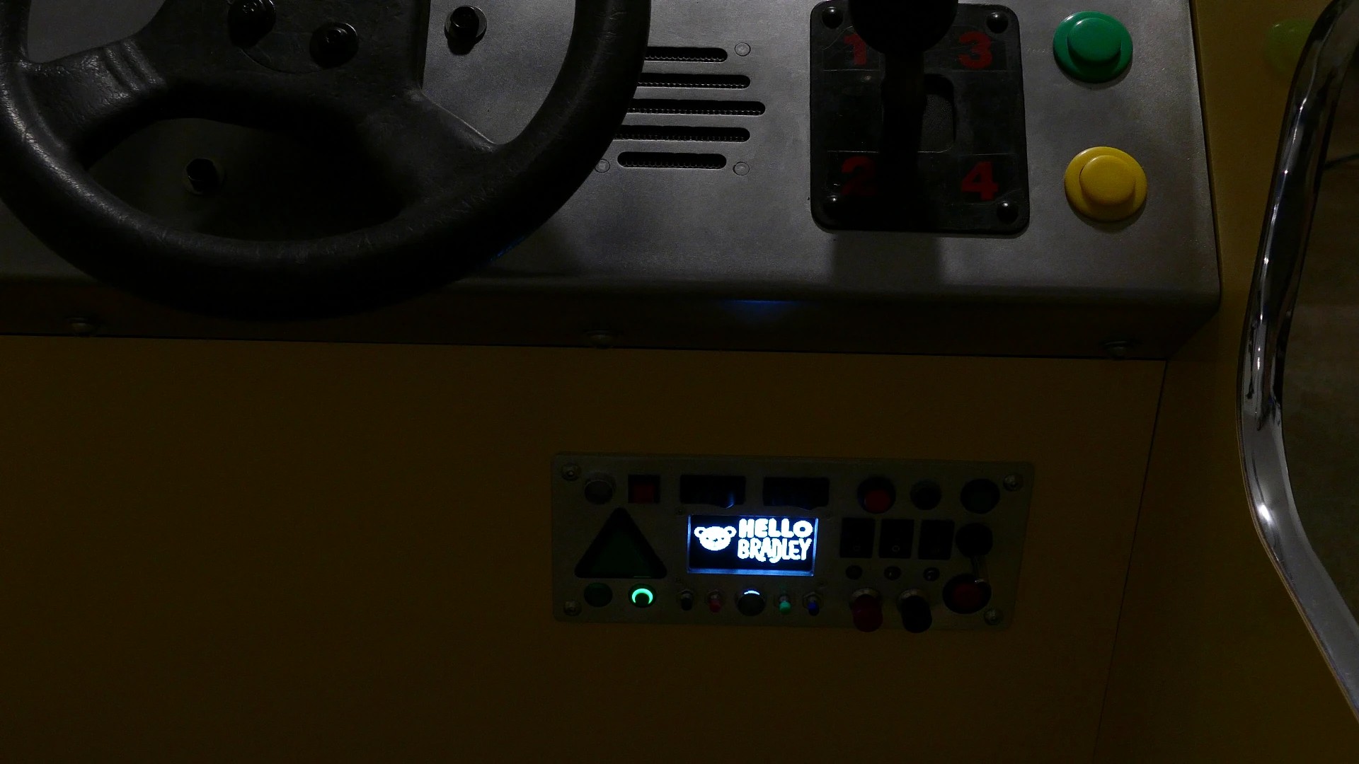
A method called hello_bradley displays the splash screen on the display. GC collect is also called to free up memory before the large image is loaded.
    def hello_bradley(self):
        """Display Hello Bradley image."""
        gc.collect()
        self.display.draw_bitmap('images/hello128X57.mono', 0, 7, 128, 57)
        self.display.present()
Here’s the main program logic. It starts by displaying the splash screen image. After 500 milliseconds it plays a greeting sound effect followed by a longer 3 second pause. After which the display buffers are cleared.
    def main(self):
        """Main program loop."""
        self.hello_bradley()
        sleep_ms(500)
        self.play_sound("Hello Bradley")
        sleep_ms(3000)
        self.display.clear_buffers()
Here’s an image of the splash screen.
Here’s the main program loop. The steering wheel indicator on the display is cleared by drawing a black filled rectangle over it. A circle is drawn to enclose the indicator. The steering wheel potentiometer is read which returns a 16-bit value. The old pot has quite a bit of jitter. I tried cleaning it, but the results were still erratic. If this were an actually gaming cabinet, I’d replace the pot. A small capacitor might also suffice. However, I was able to mitigate the noise in software. Movement is only registered if the absolute value of the 16-bit ADC wheel value minus its previous value is greater than the hysteresis threshold. This ensures the indicator doesn’t move unless the steering wheel actually turns and it prevents the indicator from oscillating when the when the wheel is near the boundary of 2 adjacent positions. When a valid movement occurs, the 16-bit value is scaled to a number between 0 and 16 to correspond with the 17 possible indicator positions. A min statement is used to catch any errant readings. Then the previous wheel position is updated to the current position. The associated coordinates are retrieved from the triangle_coords dict and the draw_polygon_coords method is called to draw a filled triangle on the display.
        while True:
            # Steering Wheel Display
            self.display.fill_rectangle(0, 0, 64, 64, invert=True)
            self.display.draw_circle(31, 36, 27)
            wheel = self.adc.read_u16()  # Read 16 bit ADC value for wheel
            # Apply hysteresis
            if abs(wheel - self.prev_wheel) > self.HYSTERESIS_THRESHOLD:
                # The pot range is approximately 2000 to 48000
                wheel_scaled = wheel // 2706  # Scale ADC output 0-16
                wheel_scaled = min(wheel_scaled, 16)  # Catch errant readings
                self.prev_wheel = wheel  # Store last clean reading
            coords = self.triangle_coords[wheel_scaled]
            self.display.draw_polygon_coords(31, 36, coords, fill=True)
Next gear is defaulted to N for neutral. The 4 shifter microswitches are read and the gear variable is set to 1, 2, 3 or 4 assuming the stick is in gear. The draw letter method is called to draw the gear number on the display. If the current gear does not equal the previously selected gear and the gear is not neutral and the gear is valid then a gear change sound effect is played. The previous gear variable is updated to the current gear. Display present is called to actually update the OLED display.
            # Gear shift display
            gear = "N"
            if self.gear1.value() == 0:
                gear = "1"
            elif self.gear2.value() == 0:
                gear = "2"
            elif self.gear3.value() == 0:
                gear = "3"
            elif self.gear4.value() == 0:
                gear = "4"
            self.display.draw_letter(95, 26, gear, self.unispace)
            if gear != self.prev_gear:
                if gear != "N" and self.prev_gear != "":
                    self.play_sound(gear)
                self.prev_gear = gear
            self.display.present()
Here’s an image of the lower control panel with the steering wheel indicator and the gear shifter number.
Next the rocker switchers for the headlights and strobes are read. Since they’re 3-state the values are added and the results will be zero for off, 1 for on and 2 for blink or breathe. If the strobes state doesn’t equal the previous state, then the previous state is updated. If the strobes value is equal to on then the expander setup_blink method is called with all zeros which cancels any blinking and sets the LED on. Else if the strobes are in the blink or breathe state then the expander breathe method is called which creates a smooth fading effect on the LEDs. Otherwise, the rocker is in the off position and the LEDs are turned off by calling setup_blink with all zeros except for the on_intensity which is set to 255
            # Headlights and strobe lights rockers
            headlights = ((not self.rocker_hl1.value()) +
                          (not self.rocker_hl2.value()))
            strobes = ((not self.rocker_strobe1.value()) +
                       (not self.rocker_strobe2.value()))
            if strobes != self.prev_strobes:
                self.prev_strobes = strobes
                if strobes == LightMode.ON:
                    self.expander.setup_blink(self.STROBE1_LED, 0, 0, 0, 0,
                                              0, 0)
                    self.expander.setup_blink(self.STROBE2_LED, 0, 0, 0, 0,
                                              0, 0)
                elif strobes == LightMode.BLINK:
                    self.expander.breathe(self.STROBE1_LED, 500, 600, 600, 250)
                    self.expander.breathe(self.STROBE2_LED, 500, 600, 600, 250)
                else:
                    self.expander.setup_blink(self.STROBE1_LED, 0, 0, 255, 0,
                                              0, 0)
                    self.expander.setup_blink(self.STROBE2_LED, 0, 0, 255, 0,
                                              0, 0)
Identical code is used for the headlights except the expander blink effect is used instead of the breathe effect. This just continuously toggles the headlights on and off.
            if headlights != self.prev_headlights:
                self.prev_headlights = headlights
                if headlights == LightMode.ON:
                    self.expander.setup_blink(self.HL1_LED, 0, 0, 0, 0, 0, 0)
                    self.expander.setup_blink(self.HL2_LED, 0, 0, 0, 0, 0, 0)
                elif headlights == LightMode.BLINK:
                    self.expander.blink(self.HL1_LED, 500, 1000)
                    self.expander.blink(self.HL2_LED, 500, 1000)
                else:
                    self.expander.setup_blink(self.HL1_LED, 0, 0, 255, 0, 0, 0)
                    self.expander.setup_blink(self.HL2_LED, 0, 0, 255, 0, 0, 0)
Next the keypad engine is read and returns the key data. If the key_data doesn’t equal the previous key_data and the key_data isn’t zero then a new button press has occurred. The previous key_data is updated to the current. The release count is set to 1. The row and column of the keypad matrix are retrieved using the get_row and get_col methods. And a method called process_input is called and passed the name of the key that was pressed. Unfortunately, the SX1509 doesn’t have a built-in way to check if a key is released. You can use the scan time and debounce time to avoid noise and chatter, but if someone holds a key down then it will keep registering button presses and in the interim the key_data can be zero. So, here’s my approach. If the previous key_data does not equal zero it means a button was previously in a pressed state. If the key_data is now zero then it could mean a release, but we can’t be sure until the scan time expires so the variable release_count is incremented. If the key_data doesn’t equal zero, then someone is definitely holding down the button and release_count is reset. If the release_count is greater than the maximum release count which is greater than the maximum number of cycles for the scan time, then previous_key data is reset to zero which indicates the keypad is now in a released state. This software-based approach works well as long as you have the max_release value dialed in right.
            # Scan I/O expander keypad
            key_data = self.expander.read_keypad()
            if key_data != self.prev_key_data and key_data != 0:
                self.prev_key_data = key_data
                self.release_count = 1
                # Find the active row and columns
                row = self.expander.get_row(key_data)
                col = self.expander.get_col(key_data)
                self.process_input(self.KEY_MAP[row][col])
            elif self.prev_key_data != 0:
                if key_data == 0:  # Increment release count if no button press
                    self.release_count += 1
                else:  # Reset release count if button still pressed
                    self.release_count = 1
                if self.release_count > self.MAX_RELEASE:  # Release button
                    self.prev_key_data = 0
Next the 2 pushbuttons that are not part of the expander keypad are polled. I wrote my own method to debounce the pushbuttons. The pin number of the black mini pushbutton is passed to the read_debounced_pin method. It will return 1 for high which is not pressed and 0 for low which is pressed. If the button is not pressed and the black_mini_pressed variable is true, then the button was pressed but it’s now released so black_mini_pressed is set to False. Else if the button is pressed and the black_mini_pressed is False then we have a new button press. The process_input method is called and passed the name of the pushbutton that was pressed. That’s the end of the main loop. It sleeps for 10 milliseconds and repeats.
            # Poll additional 2 pushbuttons not on expander keypad
            button_state = self.read_debounced_pin(self.black_mini)
            if button_state == 1 and self.black_mini_pressed:
                self.black_mini_pressed = False  # Release
            elif button_state == 0 and not self.black_mini_pressed:
                self.process_input("black_mini")  # Pressed
                self.black_mini_pressed = True

            button_state = self.read_debounced_pin(self.green_ring)
            if button_state == 1 and self.green_ring_pressed:
                self.green_ring_pressed = False  # Release
            elif button_state == 0 and not self.green_ring_pressed:
                self.process_input("green_ring")  # Pressed
                self.green_ring_pressed = True

            sleep_ms(10)
The play_sound method is used to play MP3 sound effects stored on the JQ6500. It’s wrapped in a try statement to catch any errors. The index of the passed sound title is returned from the sounds list and incremented by 1 because the JQ6500 index is 1-based instead of zero-based. Then the player.play_by_index method is called and passed the index. I really like this module because it’s so easy to add sound to your project.
    def play_sound(self, title):
        """Plays a sound effect on the MP3 module.

        Args:
            title (string): The sound effect title to play
        """
        try:
            index = self.SOUNDS.index(title) + 1
            self.player.play_by_index(index)
        except Exception as e:
            print("Error:", e)
Here’s the process_input method. It handles sound effects for button presses and also handles any associated LED effects and more. A variable process retrieves the sound effect and the LED effect if applicable. The sound effect is stored in the effect variable and then passed to play_sound which plays it. If there’s an LED effect it is stored in the variable LED. If led has a value, then the set_led_state method is called to update the LED. In the special case that the sound effect equals Hello Bradley then the hello_bradley method is called which displays the splash screen on the display for 3 seconds.
    def process_input(self, button):
        """Handles sound effects and any LED effects for given button press.

        Args:
            button (string): Name of button or switch to process.
        """
        process = self.PROCESS_MAP[button]
        effect = process['MP3']
        self.play_sound(effect)
        led = process['LED']
        if led:
            self.set_led_state(led)
        # Handle Hello Bradley
        if effect == "Hello Bradley":
            self.hello_bradley()
            sleep_ms(3000)
            self.display.clear_buffers()
The read_debounced_pin method is my custom pin debouncer. It’s passed a GPIO pin and an optional debounce_time which defaults to 50 milliseconds. The gpio pin is sampled twice at an interval equal to the debounce time. The last value is returned as long as the 2 samples are equal otherwise none is returned.
    def read_debounced_pin(self, pin, debounce_time=50):
        """Reads the GPIO pin state with debouncing.

        Args:
            pin: The pin to read
            debounce_time: Debounce time in milliseconds
        Returns: The debounced state of the pin
        """
        first_read = pin.value()
        sleep_ms(debounce_time)
        second_read = pin.value()
        return second_read if first_read == second_read else None
Here’s the set_led_state method. It takes a gpio pin number and there an optional off variable that can be used to force an LED off. If the pin number is less than 10 then it’s on the Pico. A variable LED is set to the GPIO pin as an output. If the optional off variable is true then the LED is turned off. Else, the LED is toggled. If it’s on it’s turned off, and if it’s off then it’s turned on. Otherwise, if the pin is greater than or equal to 10 then it’s on the expander. A variable roff stores the Off/Time Intensity register for the given pin and rion stores the On Intensity register for the pin. Then the LED is cycled to the next state. If roff is greater than zero, then the LED is currently breathing and should be turned off. This conditional block also fires if the optional force off parameter is specified. If rion is greater than zero, then the LED is currently off and should be turned on. Else, the LED is on and should be switched to the breathe state.
    def set_led_state(self, pin, off=False):
        """Either toggles or modifies LED state.

        Args:
            pin (int): The LED GPIO pin
            off (Optional bool): If True the LED will be turned off
        """
        if pin < 10:
            # LED connected to Pico GPIO
            led = Pin(pin, Pin.OUT)
            if off:
                led.value(0)
            else:
                led.value(not led.value())
        else:
            # LED connected to expander GPIO
            roff = self.expander.read_byte(self.expander.REG_OFF[pin])
            rion = self.expander.read_byte(self.expander.REG_I_ON[pin])
            if roff > 0 or off:
                # Currently breathing switch to off
                self.expander.setup_blink(pin, 0, 0, 255, 0, 0, 0)
            elif rion > 0:
                # Currently off, switch to on
                self.expander.setup_blink(pin, 0, 0, 0, 0, 0, 0)
            else:
                # Currently on, switch to breath
                self.expander.breathe(pin, 500, 600, 600, 250)
A main guard is inserted to allowing running the script directly. A car class is instantiated. A try statement is used to catch errors and allow for a graceful exit. The car’s main method is called to run the program. CTRL-C is caught to exit and the finally statement cleans up the display, the expander and turns off the LED’s connected to the Pico.
if __name__ == "__main__":
    print('starting program...')
    car = Car()
    try:
        car.main()
    except KeyboardInterrupt:
        print("Ctrl-C pressed.")
    finally:
        car.display.cleanup()
        car.expander.reset()
        car.set_led_state(car.GREEN_METAL_LED, off=True)
        car.set_led_state(car.GREEN_ILL_LED, off=True)
        print('Program terminated.')
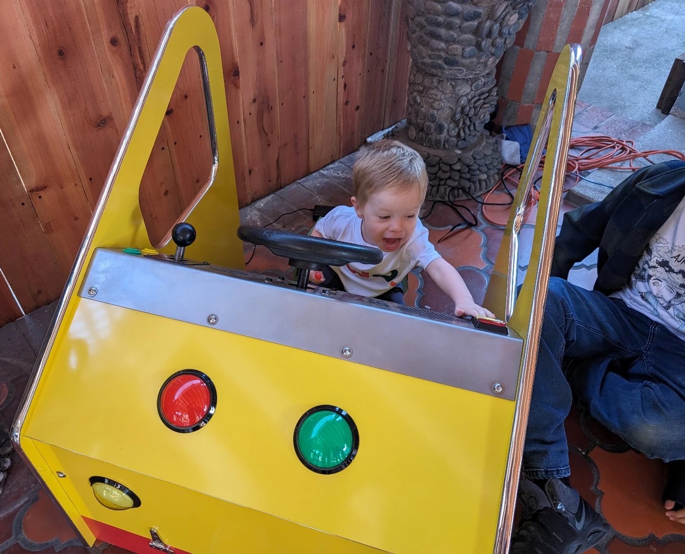
A happy birthday party!