
This MicroPython tutorial demonstrates utilizing the ESP32’s built-in capacitive touch sensors. A simple music player is constructed utilizing a JQ6500 MP3 module connected to an ESP32 via serial communication. The touch interface provides feedback by using pulse width modulation (PWM) to vary LED brightness.
This is the fifth video in my MicroPython ESP32 series.
-
- Part 1 demonstrates loading the ESP32 firmware, file manipulation with Rshell and NeoPixel LED’s.
- Part 2 uses MQTT to wirelessly transmit data from temperature/humidity sensors.
- Part 3 sets up a web server on the ESP32 that provides lighting control and sensor feedback.
- Part 4 demonstrates how to connect a color OLED display in addition to ADC and FTP.
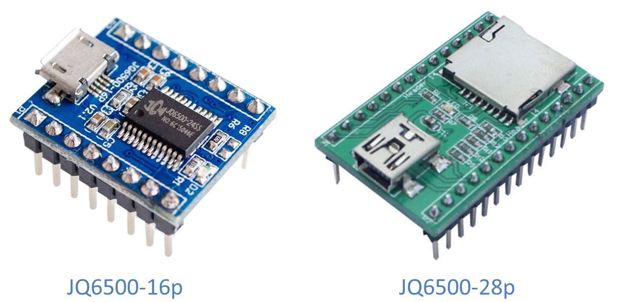
The JQ6500 MP3 module is a great way to add sound and music to your projects. It supports MP3 and WAV formats. The device requires 5 V power but it uses 3.3 V serial communication which makes it easy to connect to 3.3 V devices such as the ESP32 and the Raspberry Pi. It has amplified speaker and stereo headphone outputs with 30 volume levels. There is a micro-USB port which can be used to upload music files from a PC. It comes with Windows support but there’s also a Linux library available. The JQ6500 can be purchased for under $2 on AliExpress.

It comes in 2 versions. The 16P has only a few megabytes of memory to store sound files which is fine for sound effects. The 28P adds an SD card slot which supports up to 32 GB of music.
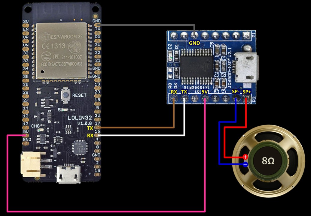
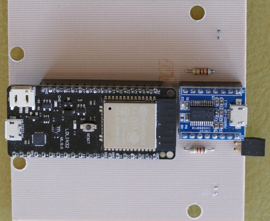
The JQ6500 is easy to hook up to the ESP32. The JQ6500 serial RX pin is connected to GPIO 17 on the ESP32 which is UART2 TX. The JQ6500 TX pin is connected to GPIO 16 which is RX. Remember RX always goes to TX and TX goes to RX. It’s a common mistake to connect the RX to RX or TX to TX. You might think that you should be connecting the serial lines to the pins marked TX and RX on the ESP32. However, these are UART0 which is reserved by the system for the REPL and logging. There’s also issues with using UART1. Fortunately, the ESP32 has UART2 on GPIO 16 and 17 which is available and works great. The JQ6500 is connected to the ESP32’s 5 V pin and to a ground. A speaker is connected to the speaker plus and minus pins. The driver supports a 3 watt 8 ohms speaker.
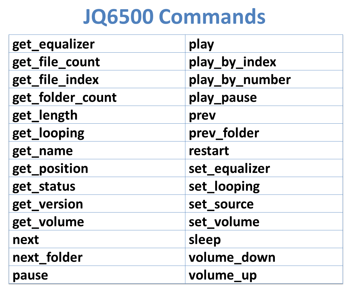
I wrote an open source MicroPython library for the JQ6500. It is available on my GitHub site. There are commands to control playback, volume, EQ, status, source, etc. For the code example the play_pause() command will toggle the play state. Prev() and next() will allow navigation between songs and set_volume() will control the volume level.
The ESP32 has 10 touch sensor pins 0-9. They can detect capacitive variations induced by touching or approaching the pads with a finger or other object. With this technology you can create touch buttons, sliders, keypads and even non-contact fluid level sensors. There are many benefits to capacitive touch controls: no mechanical parts which save costs and improves reliability, completely sealed surfaces that are waterproof and a modern look with a flexible design.
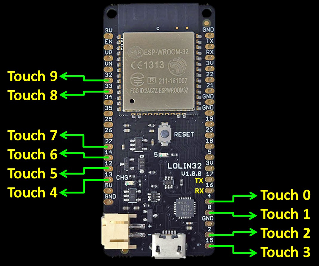
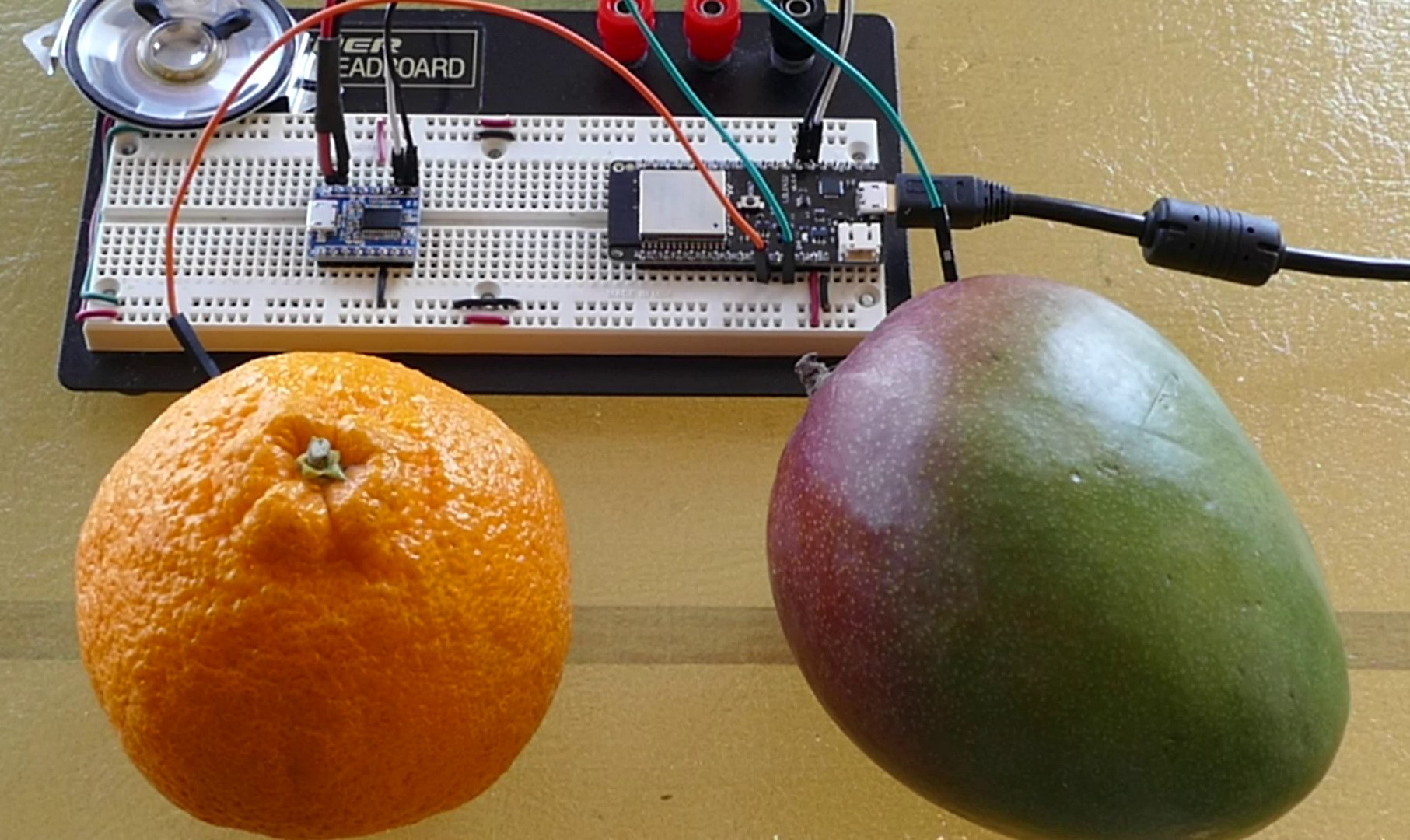
A common demo of touch capacitance involves produce and beverage musical instruments. Here’s an orange and a mango. A jumper wire is plugged into the ESP32’s touch sensor 5 which is GPIO 12. The other end is stuck into the mango. Another jumper is plugged into touch sensor 7 which is GPIO 27. The other end goes into the orange. The JQ6500 is loaded with musical chime tracks.
Here is the MicroPython code to play chime tracks when a fruit is touched. A capacitance ratio is recorded when the fruits are touched. The lower the percent the greater the change in capacitance and the more probable a touch event has occurred. A press will be registered if the ratio is between 40 and 95 percent. Anything higher than 95 could easily be a false positive from parasitic capacitance. Very low percents can also be errors due to interference. There are many software strategies to deal with errors. You can take multiple samples. You can analyze the duration of presses. You can examine the interpolation of adjacent sensors. For this simplistic example I’m just using a single reading.
"""TouchPad Fruit Demo."""
from time import sleep
from jq6500 import Player
from machine import Pin, TouchPad

# Initialize JQ6500
player = Player(port=2)
player.set_volume(30)

touch5 = TouchPad(Pin(12))
touch7 = TouchPad(Pin(27))
threshold5 = []
threshold7 = []

# Scan each TouchPad 12 times for calibration
for x in range(12):
    threshold5.append(touch5.read())
    threshold7.append(touch7.read())
    sleep(.1)

# Store average threshold values
threshold5 = sum(threshold5) // len(threshold5)
threshold7 = sum(threshold7) // len(threshold7)
print('Threshold5: {0}'.format(threshold5))
print('Threshold7: {0}'.format(threshold7))

try:
    while True:
        capacitance5 = touch5.read()
        capacitance7 = touch7.read()
        cap_ratio5 = capacitance5 / threshold5
        cap_ratio7 = capacitance7 / threshold7
        # Check if a TouchPad is pressed
        if .40 < cap_ratio5 < .95:
            player.next()
            print('Touch5: {0}, Diff: {1}, Ratio: {2}%.'.format(
                  capacitance5, threshold5 - capacitance5, cap_ratio5 * 100))
            sleep(.2)  # Debounce press
        if .40 < cap_ratio7 < .95:
            player.prev()
            print('Touch7: {0}, Diff: {1}, Ratio: {2}%.'.format(
                  capacitance7, threshold7 - capacitance7, cap_ratio7 * 100))
            sleep(.2)  # Debounce press

except KeyboardInterrupt:
    print('\nCtrl-C pressed.  Cleaning up and exiting...')
finally:
    player.clean_up()
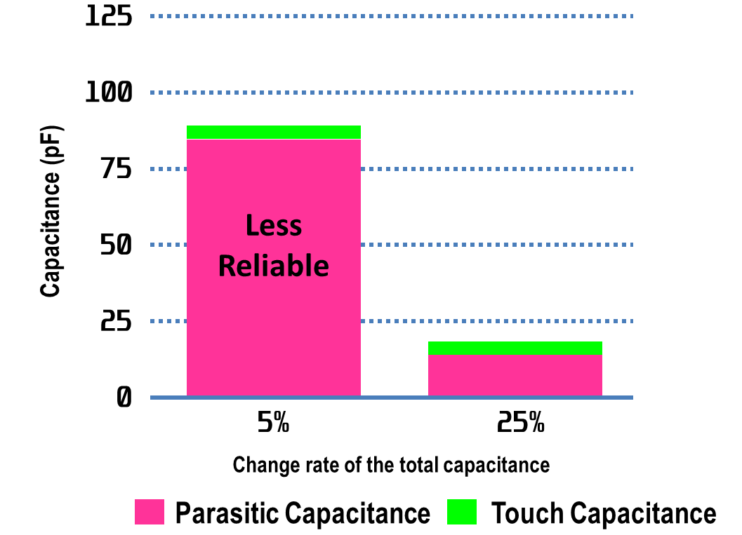
In any capacitive touch design there are going to be sources of capacitance other than a touch, such as capacitance between the traces, the electrodes and the circuit ground. These are referred to as parasitic capacitance and adversely affect the reliability of the touch sensors.

A lower parasitic capacitance results in a greater percent change in touch capacitance which provides more reliability because of the higher contrast between touched and untouched states. Improved sensor stability is achieved by minimizing parasitic capacitance and maximizing touch capacitance.
Fruit is fun but now let’s go for a more useful design: a touch controlled MP3 player. To achieve better reliability I created a PCB. There are 3 touch buttons on the bottom which will be used for reverse, play/pause and forward. On the top there is a slider comprised of 5 interwoven electrodes. This will be the volume control. It will function similarly to the linear SoftPot demonstrated in my previous video.
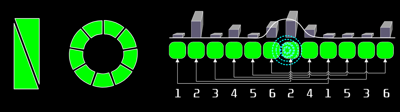
Another way to design a slider is with just 2 triangular pads forming a rectangle. As you move a finger along the slider the capacitance rises on 1 pad and lowers on the other. You can also have circular sliders and you can increase slider resolution by multiplexing touch pads and then using an interpolation algorithm to determine finger position. The example pictured on the right doubles your available touch pads.
Capacitive touch design is a very involved subject. I’m only going to briefly discuss some of the strategies that I worked into the board to achieve lower parasitic capacitance and more consistent performance. One of the best sources with respect to ESP32 touch sensors is the Espressif Touch Sensor Application Notes. Texas Instruments also has an excellent Capacitive Touch Hardware Design Guide. The ESP32 Technical Reference Manual also has a capacitive touch sensor section.
Making PCB’s yourself is very easy and inexpensive. All you need is a laser printer, some glossy paper, an iron and common chemicals found at the market and hardware store. I prepared detailed notes on the toner transfer PCB method. Here’s another helpful site on DIY PCB fabrication.
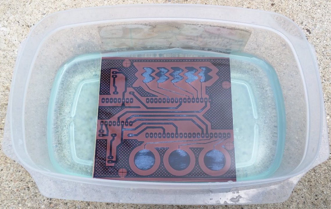
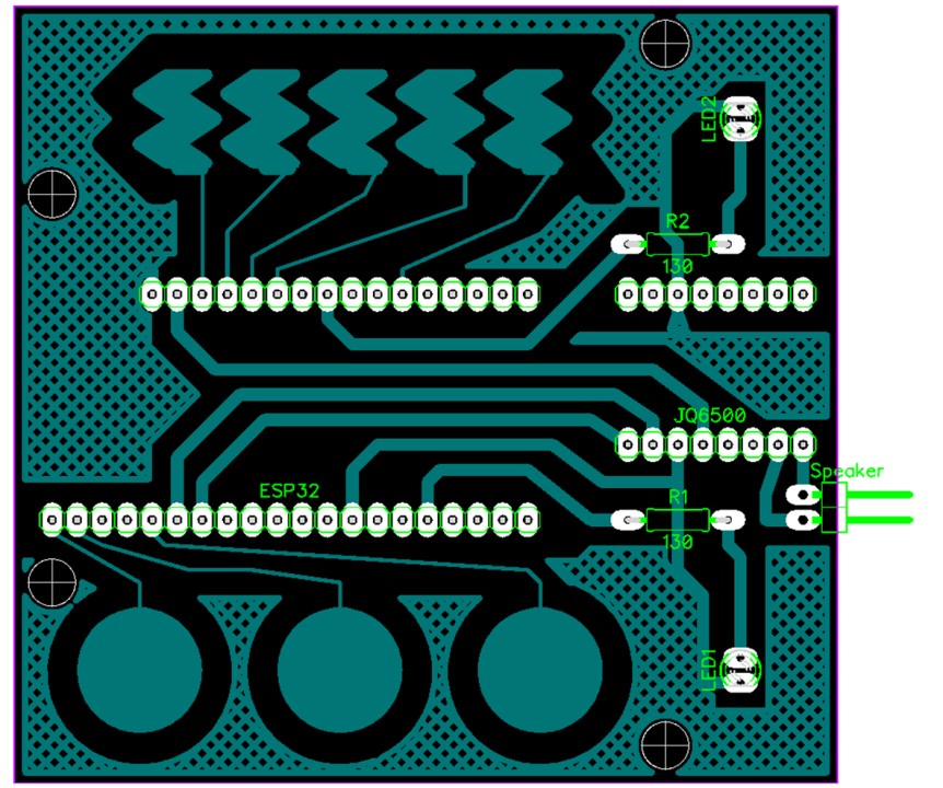
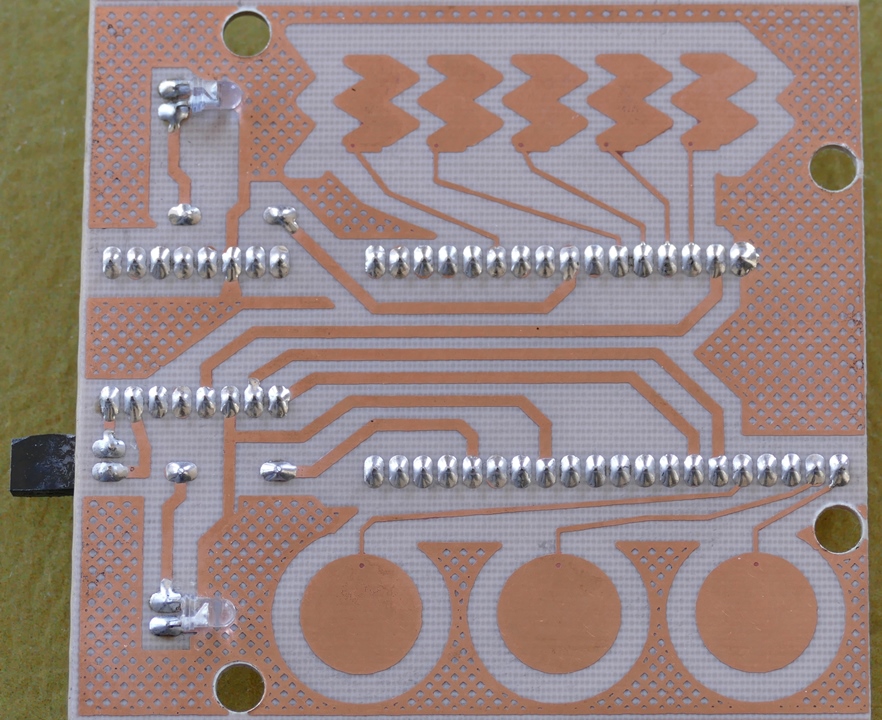
Here’s the finished PCB. For the buttons, rounded patterns are recommended and they should be about the diameter of a finger (8 to 15 mm). They should be spaced at least 5 mm apart to avoid false positives. The traces for the electrodes need to be short. They should not exceed 300 mm. Notice I’ve made the trace widths for the touch pads much narrower than the other traces. Ideally the trace width shouldn’t exceed .18 mm. It’s also important to route traces away from the path of fingers so the traces don’t register touches. The traces should also maintain distance from ground and other traces. There should be at least a 1 mm gap between the electrodes and the ground plane. The ground area helps reduce interference but it also increases parasitic capacitance. Therefore a cross-hatched ground pattern is used as a compromise (usually between 10 and 40 percent fill). Avoid putting components on the other side of the board directly opposite the touch pads. On this board I have most of the components in the center and the touch pads on the outside.
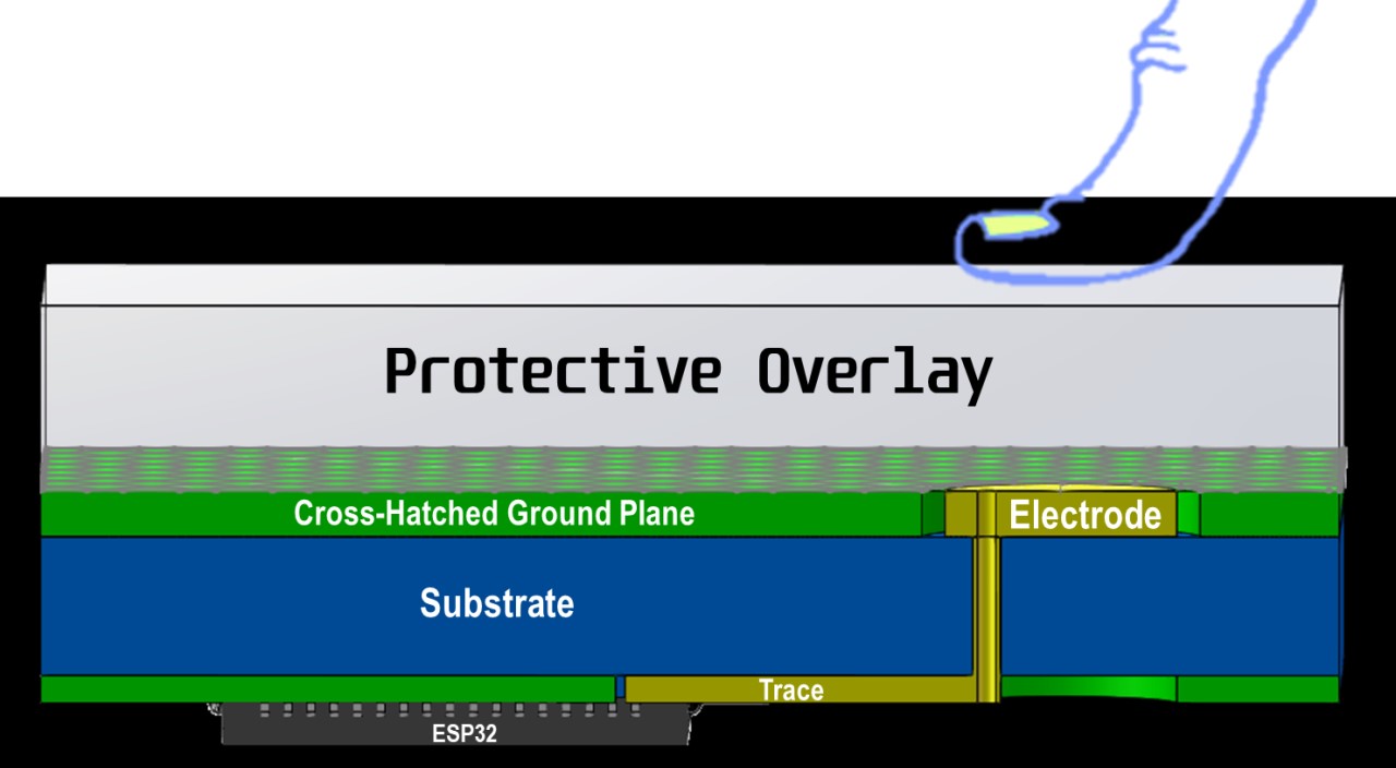
It’s good practice to place non-conductive overlays over the touch pads. This protects the pads from the environment and reduces the possibility of ESD damage. Capacitance is inversely related to distance, therefore, thinner overlays work better, but materials with higher dielectric constants such as glass can allow for thicker displays. The dielectric constant is the amount of electric field energy that a material can store when voltage is applied. Higher provides more capacitance. Air has a very low dielectric constant therefore air gaps between the electrodes and overlays should be avoided.
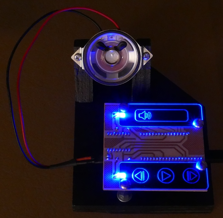
Here’s the finished player mounted with a speaker to a wood base. I’m using 0.7 mm polycarbonate for the overlays. I painted 1 side black and used my cnc mill to etch the button icons. The design is inverted so the painted side installs down and the glossy smooth side up.
Here’s the code for the MP3 player.
"""TouchPad MP3 Player Demo."""
from time import sleep
from jq6500 import Player
from machine import Pin, PWM, TouchPad

# Initialize JQ6500
player = Player(port=2)
player.set_volume(30)

# Configure LED PWM (default frequency, 25% duty cycle)
buttons_led = PWM(Pin(22))
slider_led = PWM(Pin(25))
buttons_led.duty(256)
slider_led.duty(256)

touch = {
    0: TouchPad(Pin(4)),
    1: TouchPad(Pin(2)),
    2: TouchPad(Pin(15)),
    3: TouchPad(Pin(32)),  # TouchPad pin 32 and 33 reversed (fixed?)
    4: TouchPad(Pin(27)),
    5: TouchPad(Pin(14)),
    6: TouchPad(Pin(12)),
    7: TouchPad(Pin(13))}

threshold = {
    0: [],
    1: [],
    2: [],
    3: [],
    4: [],
    5: [],
    6: [],
    7: []}

commands = {
    0: player.prev,
    1: player.play_pause,
    2: player.next}

volume = {
    0b00001: 0,
    0b00011: 9,
    0b00010: 12,
    0b00110: 15,
    0b00100: 18,
    0b01100: 21,
    0b01000: 24,
    0b11000: 27,
    0b10000: 30}

print('Calibrating...')
# Scan each TouchPad 12 times
for x in range(12):
    for i in range(8):
        threshold[i].append(touch[i].read())
    sleep(.1)
# Store average threshold values
for i in range(8):
    print('Range{0}: {1}-{2}'.format(i, min(threshold[i]), max(threshold[i])))
    threshold[i] = sum(threshold[i]) // len(threshold[i])
    print('Threshold{0}: {1}'.format(i, threshold[i]))

try:
    while True:
        press = False
        slider_volume = 0
        for i in range(8):
            capacitance = touch[i].read()
            cap_ratio = capacitance / threshold[i]
            # Check if current TouchPad is pressed
            if i < 3 and .5 < cap_ratio < .93:
                press = True
                buttons_led.duty(1023)
                # Execute selected command
                commands[i]()
                sleep(.1)  # Debounce button press
                print('Pressed {0}: {1}, Diff: {2}, Ratio: {3}%.'.format(
                      i, capacitance,
                      threshold[i] - capacitance, cap_ratio * 100))
            elif i >= 3 and .5 < cap_ratio < .95:
                press = True
                slider_led.duty(1023)
                slider_volume |= 1 << (i - 3)

                print('Pressed {0}: {1}, Diff: {2}, Ratio: {3}%.'.format(
                      i, capacitance,
                      threshold[i] - capacitance, cap_ratio * 100))
        if press is False:
            # Dim LED's to 25% if no press
            buttons_led.duty(256)
            slider_led.duty(256)
        elif slider_volume:
            if slider_volume in volume:
                print('Slider: {0}'.format(volume[slider_volume]))
                player.set_volume(volume[slider_volume])
                sleep(.1)  # Debounce slider
            else:
                print('Invalid volume: {0}'.format(slider_volume))
        sleep(.1)

except KeyboardInterrupt:
    print('\nCtrl-C pressed.  Cleaning up and exiting...')
finally:
    player.clean_up()
    buttons_led.duty(0)
    slider_led.duty(0)
In Part 6 of this tutorial a LoBo MicroPython WebSocket server will broadcast temperature data from a DS18b20 sensor connected to an ESP32. A web page built with React and MobX State Tree on a Raspberry Pi will be the client.