
This project adds solar powered sensors and home automation to my vegetable garden and transmits the data using MQTT for review and control on a mobile app.
Here’s the raised garden bed set up in my backyard. It’s made by an Australian company called Vegepod.
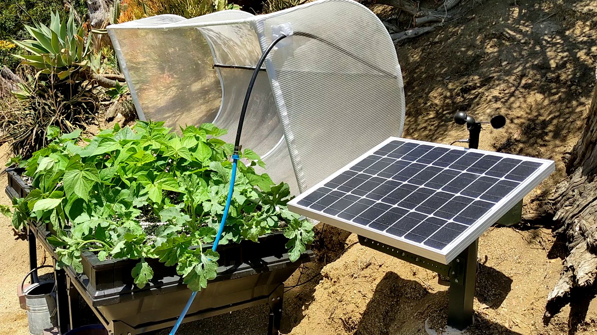
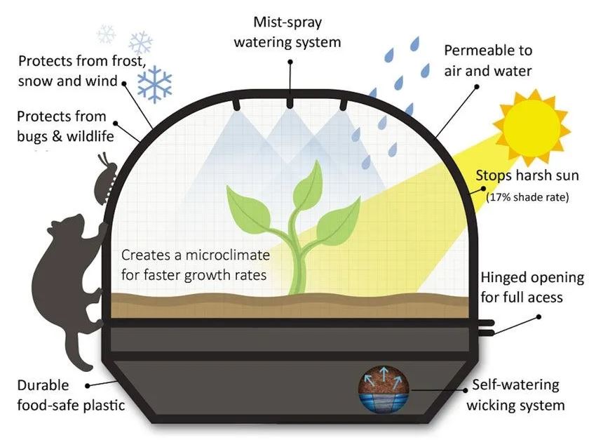
The canopy protects the vegetables from deer, squirrels and other pests. It also reduces weeds and mitigates harsh weather. Yet the permeable canopy doesn’t block sun light, rain or fresh air. There are 4 pods that utilize a wicking system to water the plants from below. Underneath the platform in each pod is a reservoir. Irrigation water drains through the soil and is collected. Vegepod claims, the vegetables can last for weeks without watering once the reservoirs are full. There’s a built-in mist sprayer on the top of the canopy that I have connected to an automated sprinkler valve.
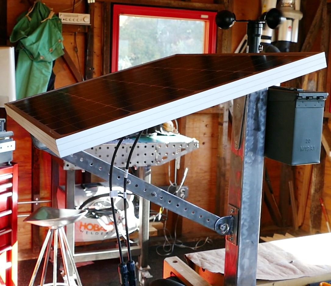
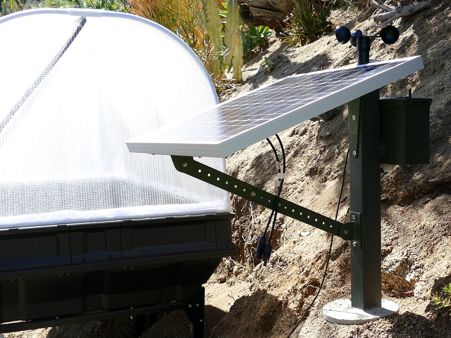
I fabricated a mounting for a solar panel and an electronics enclosure. I used scrap pieces of steel flat bar and square tubing. The panel bracket is adjustable so the angle can be optimized for the season. It’s currently at about 17 degrees. An inexpensive water tight steel ammo can will hold the battery, solar charge controller and other electronics. A wind speed sensor caps the top of the tube.
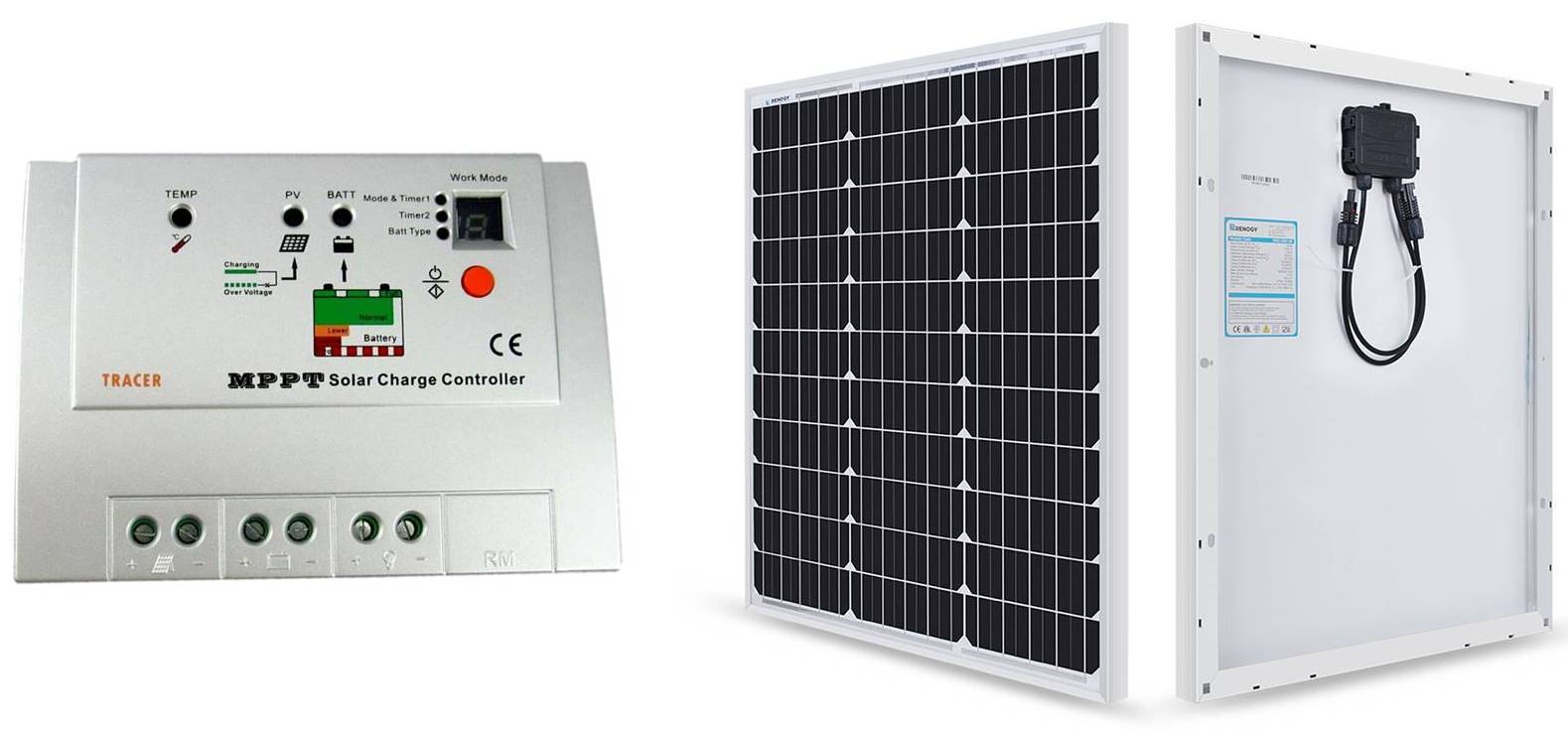
I’m using the MPPT solar charge controller and solar panel from my previous Raspberry Pi Solar Serial REST API tutorial.
In the previous tutorial, I used a Raspberry Pi to gather solar data and transmit it to a React Native app. This project will use an ESP32 instead and transmit the data using MQTT to Home Assistant which is an open source home automation system. I chose this approach because the previous React Native app that I developed in Expo is a chore to maintain. Over the past 4 years I’ve had 5 GitHub requests to upgrade my app so it works with the latest version of Expo and I’ve updated it 5 times which required reworking the navigation system, addressing deprecated modules, keeping up with changes to state and life cycle models, etc. I don’t use Expo anymore because addressing all the breaking changes between versions is too time consuming. With Home Assistant, I don’t have to worry about maintaining an app. Especially now that Home Assistant has released GUI support as opposed to a strictly YAML based system.
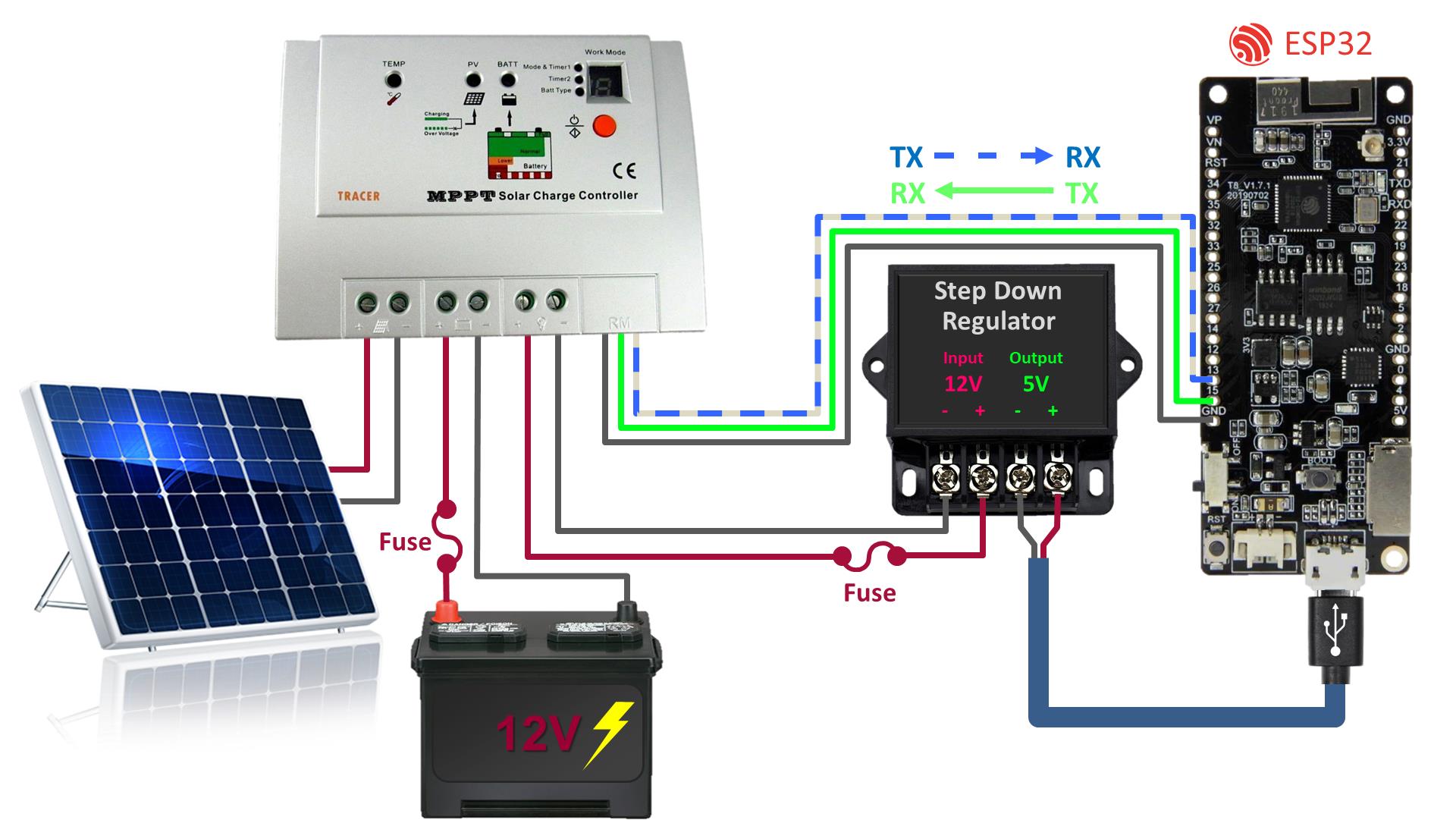
The wiring is very intuitive. The positive and negative leads from the panel are connected to the corresponding terminals on the controller. The positive and negative terminals from a 12 V battery are also connected to their corresponding terminals. An inline fuse should be placed within 15 centimeters of the battery’s positive terminal. An ESP32 running MicroPython will be used to poll the controller for voltage and current levels. A step down regulator will drop the 12 VDC output of the controller down to 5 V to power the ESP32 via its micro USB jack. The 3.3 V TTL communication lines from the MPPT charge controller are connected to the ESP32’s serial port #2. TX to RX GPIO13 and RX to TX GPIO15. The grounds are also connected. For a more detailed look at the wiring please watch the previously mentioned tutorial.
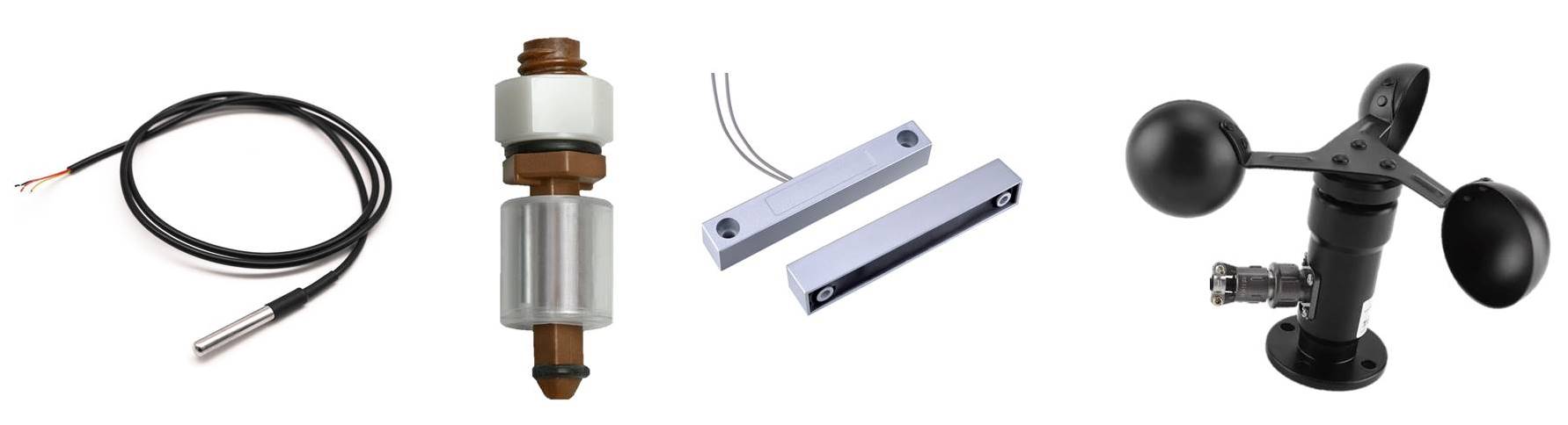
In addition to collecting solar power and battery data, the TTGO T8 ESP32 (datasheet) will also monitor 4 other sensors. The temperature in the Vegepod will be monitored with a DS18B20 (datasheet) which is a very reliable outdoor temperature sensor. The reservoir water level will be monitored with mechanical float switches (datasheet). A magnetic reed switch will monitor if the canopy is open or closed. An anemometer (user manual) will watch out for windy conditions especially if I forget to close the canopy. I live in an area with strong winds.
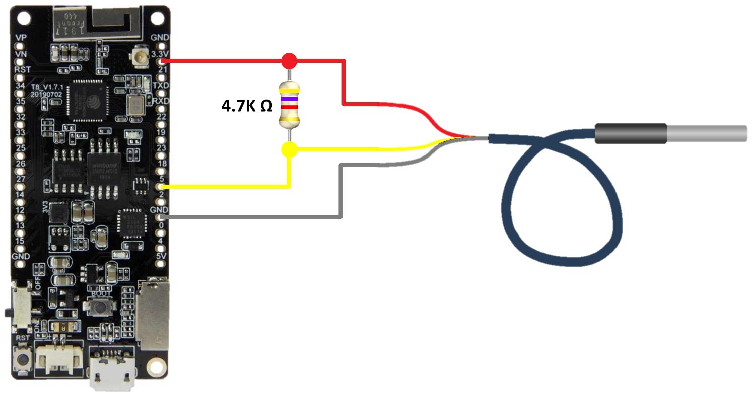
The DS18B20 temperature sensor has 3 wires. The black ground wire is connected to a ground on the ESP32. The red Vcc wire is connected to a 3.3 V pin. The yellow data wire is connected to GPIO5. I used a 10K ohm pull-up resistor placed across the Vcc and data lines. However, the datasheet recommends a 4.7K ohm value which will probably be more reliable especially on longer wire runs. Here are guidelines for reliable long line 1-Wire networks. By the way you don’t have to use GPIO5 for the data. Any available input/output GPIO should work for the data line.
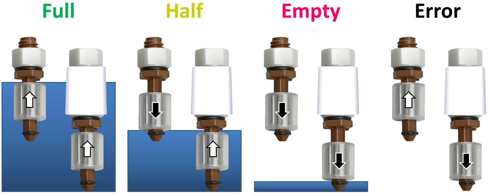
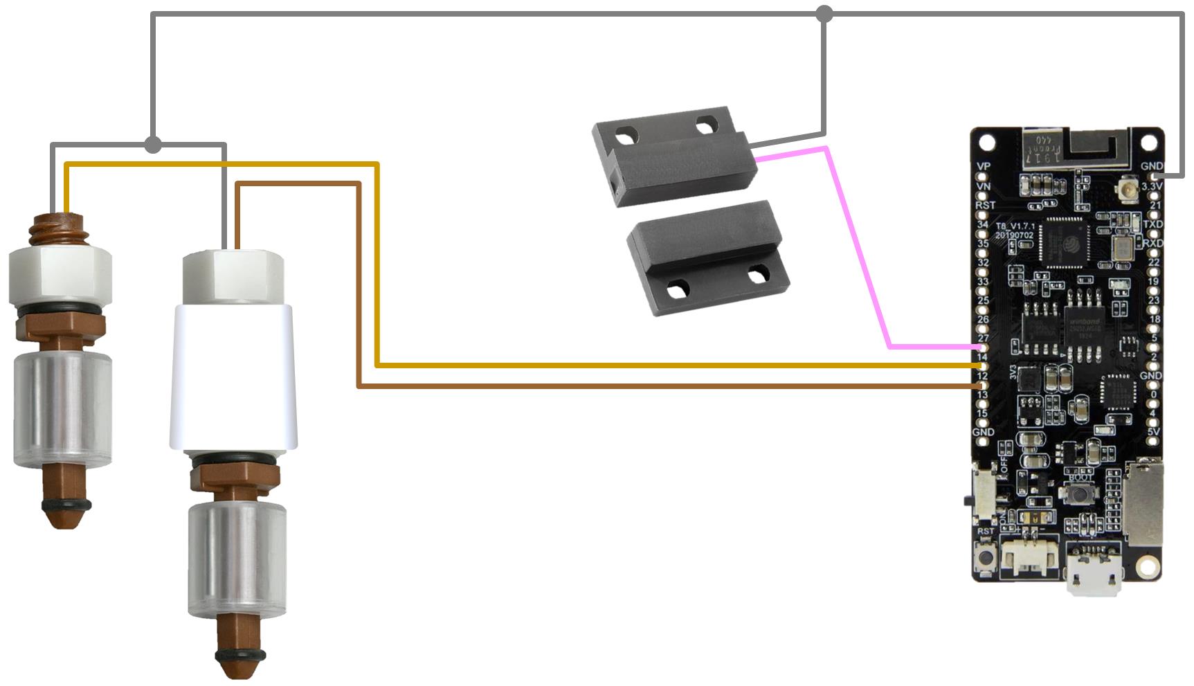
Liquid level switches will be used to monitor the water level in the Vegepod reservoir. The switches are mechanical and don’t require power which is well suited for battery power. The magnetic switches are fired based on whether the float is up or down reflecting the water level. These food-safe polypropylene level sensors are preferable to soil moisture sensors because they are not susceptible to corrosion from wet soil that can leach unhealthy material into the soil. The 2 switches will be offset. This will allow for 3 level readings. If both switches are up then the reservoir is full. If the top is down and the bottom one is up then the reservoir is half full. If they are both down then the reservoir is empty. If the top one is up and the bottom one is down then something is broken and an error state exists.
The liquid level sensors are easy to wire to the ESP32 because they are just like regular switches. One lead from each sensor is connected to a ground on the ESP32. The other lead from the top one is connected to GPIO14. The other lead from the bottom one is connected to GPIO12. Additionally, the magnetic reed switch used to monitor the state of the canopy is also just a switch. One lead is connected to ground and the other lead is connected to GPIO27. A magnet on the canopy will align with the reed switch on the pod when the canopy is closed. When the magnet is aligned the switch will close and vice versa.
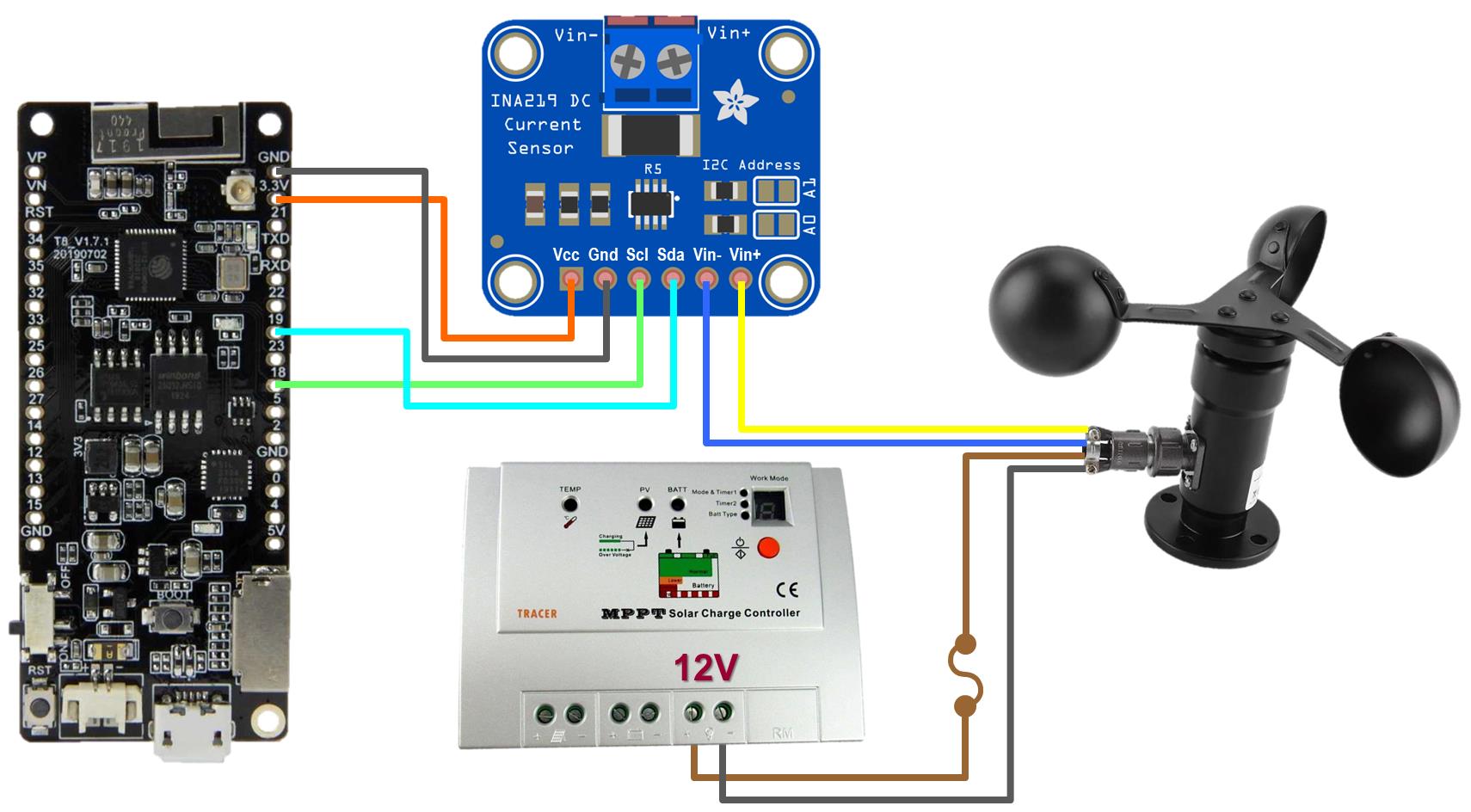
Connecting the wind sensor requires a little more work. It requires 12 V power so it will powered directly from the 12 V load terminals on the solar charge controller. The wind sensor’s black ground wire is connected to the negative terminal and the brown wire is connected to the 12 V positive terminal. It’s recommended to use an inline fuse. The wind speed sensor outputs a varying current which has a linear correlation to the wind speed. The easiest way to measure current is with an INA219 current sensor (datasheet). I have a previous tutorial dedicated to the INA219 current sensor. The INA219 ground is connected to a ground on the ESP32. The Vcc pin is connected to a 3.3 V pin. The INA219 communicates using the I²C protocol. The SCL (serial clock) pin is connected GPIO18. The SDA (serial data) pin is connected to GPIO 19. The yellow wire from the wind sensor is connected to the Vin positive pin. The blue wire is connected to the Vin negative pin. The INA219 will transmit a digital number representing the current from 4 to 20 mA which translates from 0 to 30 meters per second of wind speed (about 108 kilometers per hour or 67 miles per hour.)
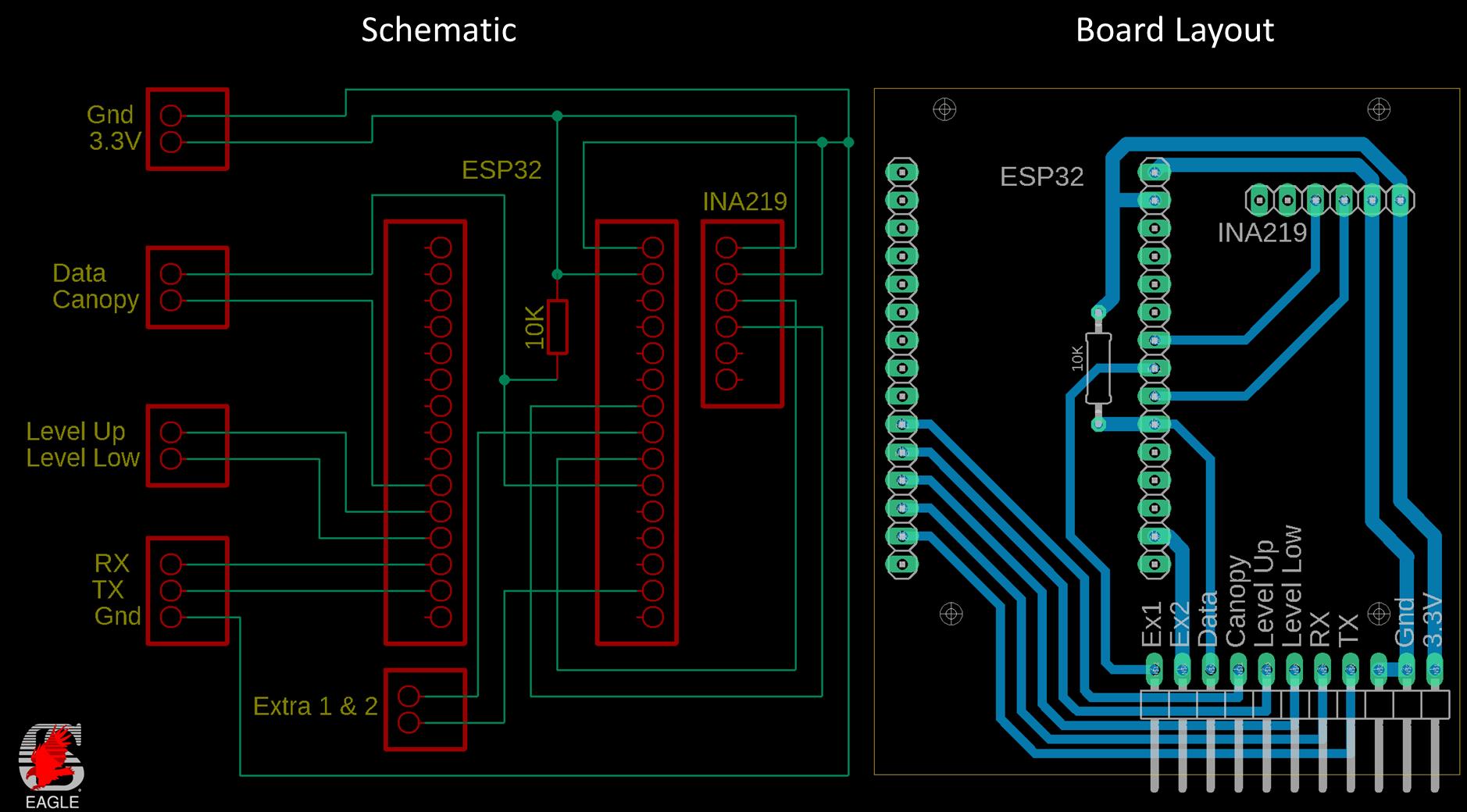
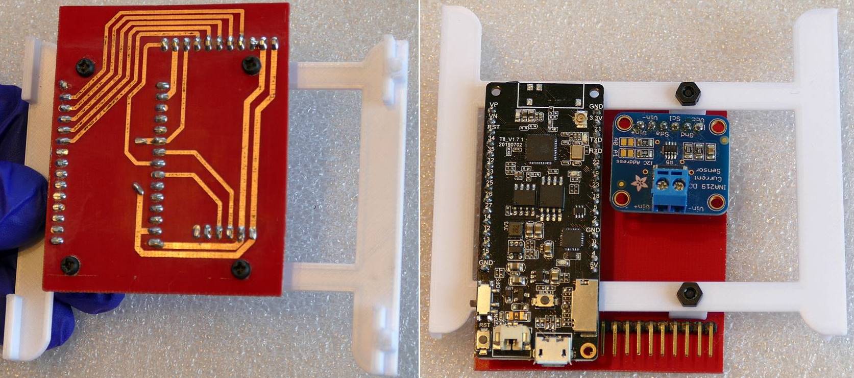
I designed a very simple PCB to hold the ESP32, the INA219 and pin headers for easy wire connections. This will simplify the wiring in the outdoor enclosure and provide a more tidy and easy to maintain environment.
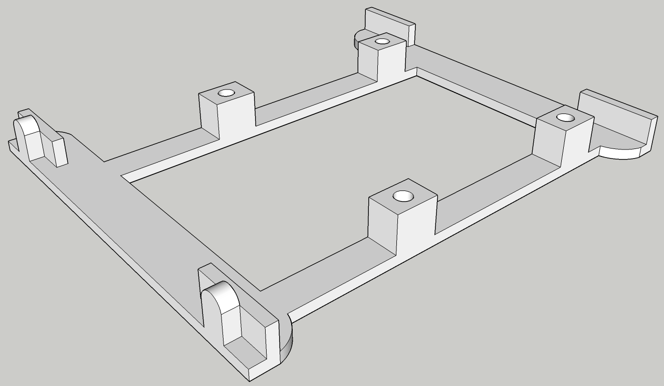
I designed and 3D printed a bracket to hold the PCB in the outdoor enclosure. The bracket mounts to and also secures the solar charge controller.
Here’s the PCB which I etched myself, and the bracket 3d printed in white PLA. The ESP32 plugs into the female pin headers on the left. And the INA219 plugs into the female pin headers on the right. The right angle male pin headers are for the sensor wire connections.
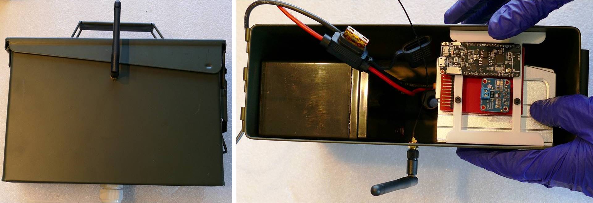
Here’s a 30 caliber metal ammo can. I mounted a WiFi antenna on the side because it’s effectively a faraday cage that blocks electromagnetic fields. The lid is easily removed and has a liquid tight rubber gasket. I drilled a hole in the bottom of the case and installed a strain relief connector for the wiring. Turning the connector compresses a grommet creating a good seal around the wires. A 12 V 7.2 Ah rechargeable sealed lead acid battery powers the electronics. Since the battery is sealed it can be mounted on its side to maximize space in the can. The MPPT solar charge controller is also mounted on its side. The can is a good fit for the battery and controller and there is still enough room for the electronics and wiring. The controller is held in place by the PCB bracket which locks into the holes on the side of the controller. Once the bracket is fit, the controller is held securely. A 5 A blade fuse is inline with the battery’s positive lead in a waterproof harness.
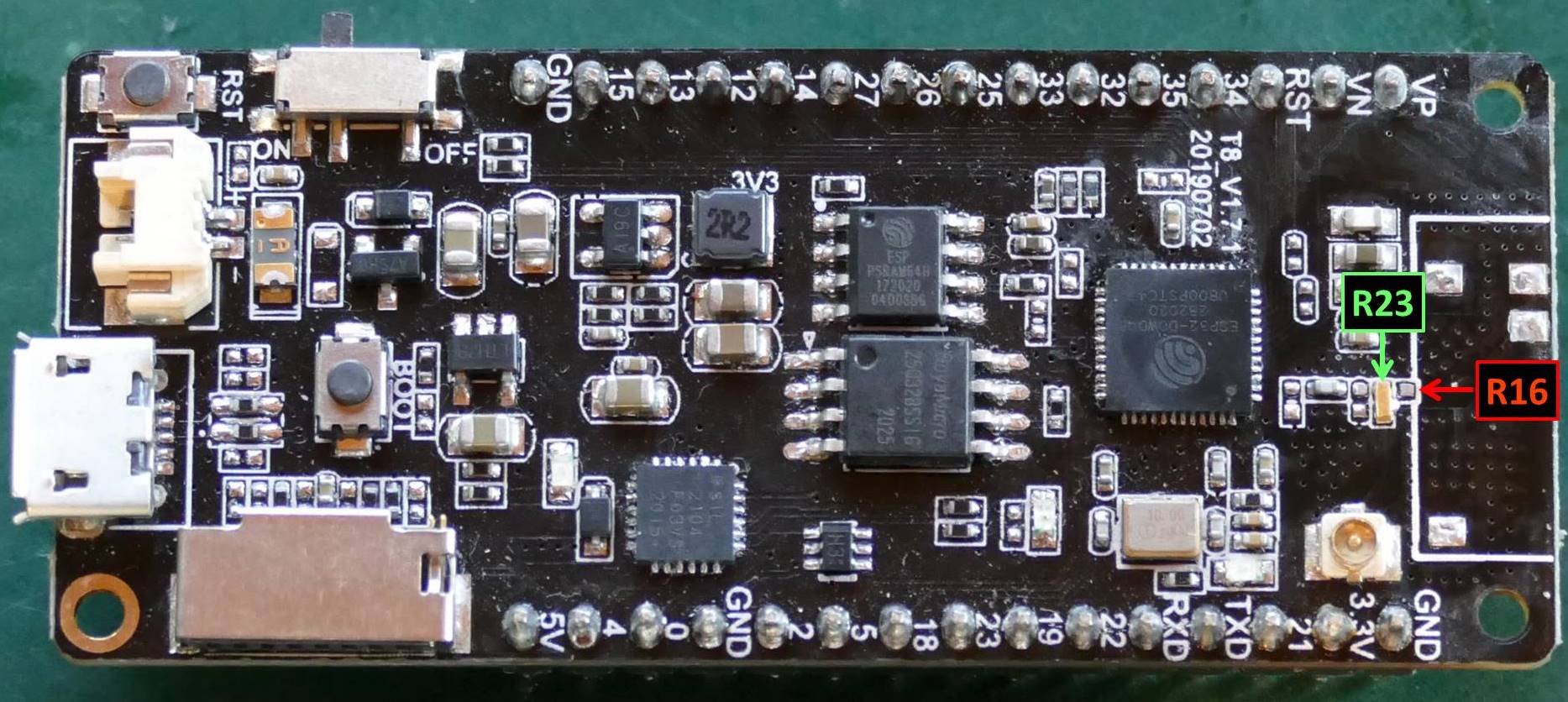
The antenna wire plugs into the external miniature RF connector on the ESP32. The antenna jack on the TTGO T8_v1.7.1 ESP32 (datasheet) was disabled by default. It’s necessary to move the zero ohm R16 resistor to R23 to enable the antenna jack. I removed the built-in antenna and the resistor R16. I dropped and lost the 0402 resistor on the dirty floor of my workshop so I cut a 1 mm piece off a gold plated female pin header and soldered it across R23.
I sunk the square steel tube in a concrete footing next to the Vegepod and gave it a coat of camo green paint. The solar panel mount is powder coated a matching green.
Here’s a short MicroPython program I wrote called vegepod.py. The DS18X20 library supports the DS18B20 temperature sensor. The INA219 library is for the INA219 current sensor. The info module from logging import is required by the INA219 library. Const is to declare constants. I2C, Pin and UART are for controlling the I²C bus, the GPIO pins and the serial ports respectively. The onewire library is for the onewire bus that drives the DS18B20 temperature sensor. I wrote the settings library and get_p2 function to obfuscate the MQTT password rather than hard coding it. I then precompiled the program into an MPY binary container which is only importable by MicroPython programs. It’s not technically secure but it would require much more effort to hack than a password stored in plain text. The tracer library supports the solar charge controller. This is a MicroPython port I created of the XXV python library that I used in my Raspberry Pi Solar Serial REST API tutorial. Ujson allows converting Python objects to JSON. The umqtt.simple library contains a light weight MQTT client for publishing and subscribing to MQTT topics. I previously posted a Raspberry Pi MicroPython MQTT tutorial.
from micropython import const  # type: ignore
from machine import I2C, Pin, UART  # type: ignore
from onewire import OneWire, OneWireError  # type: ignore
from ds18x20 import DS18X20  # type: ignore
from ina219 import INA219
from logging import INFO
from settings import get_p2
from tracer import Tracer, TracerSerial, QueryCommand
from time import sleep
from ujson import dumps
from umqtt.simple import MQTTClient
An MQTT client is instantiated. A unique ID is assigned. The server IP address is specified. For the server, I’m running the open source Mosquitto package on a Synology NAS. I have had the Synology NAS running in my very hot attic for a decade. Despite its age, Synology still provides full firmware and software updates on a frequent basis. The NAS is user friendly and very self-sufficient. It has hot swappable hard drives configured in a redundant RAID. It monitors its health and can predict hard drive failures. It monitors security and recommends best practices. You can also run Mosquitto on a Raspberry Pi which I demonstrated in the aforementioned tutorial.
# Configure MQTT client
client = MQTTClient(client_id="vegepod_client",
                    server="192.168.7.27",
                    port=1883,
                    user="mqtt",
                    password=get_p2())
Several sensor constants are defined. Empty, Mid, Error and Full represent the bitwise state of the water level sensors. Canopy_On and Canopy_Off indicate the binary state of the Vegepod canopy. Level_upper is set to GPIO14. The GPIO is set to input to read the level sensor switch and the pull-up is turned on so the pin doesn’t float. Level_lower is set to GPIO12 and is also an input with the pull-up on. Canopy_magnet is set to GPIO27 and is set as an input to read the reed switch. The pull-up is also set on. Two extra GPIO pins 23 and 4 are defined as inputs. These are just in case I decide to add any other sensors in the future.
# Sensor constants
EMPTY = const(0)
MID = const(1)
ERROR = const(2)
FULL = const(3)
CANOPY_ON = const(0)
CANOPY_OFF = const(1)

# Configure GPIO inputs
level_upper = Pin(14, Pin.IN, Pin.PULL_UP)
level_lower = Pin(12, Pin.IN, Pin.PULL_UP)
canopy_magnet = Pin(27, Pin.IN, Pin.PULL_UP)
extra1 = Pin(23, Pin.IN, Pin.PULL_UP)
extra2 = Pin(4, Pin.IN, Pin.PULL_UP)
Next the INA219 is configured. A constant shunt_ohms is set to .1. This is the value of the shunt resistor on the INA219 breakout board. The I²C bus zero is instantiated. Serial clock is set to GPIO18 and serial data is set to GPIO19. An INA219 sensor is defined and passed the shunt ohms, the I²C bus and the maximum expected amps which is set to 40 mA. The wind sensor shouldn’t go above 20 mA but I’m leaving some optional overhead. The ina.configure method is called. Voltage range is set to 16 V. The wind sensor is 12 V. The gain is set to 40 mV which is the lowest option. The bus and shunt ADC are set to ADC_128 SAMP, which provides the highest 12 bit resolution and performs 128 samples per read for more reliability. The ina.sleep method is called to put the INA219 sensor to sleep and save power until it’s needed.
# Configure INA219
SHUNT_OHMS = 0.1
i2c = I2C(0, scl=Pin(18), sda=Pin(19))
ina = INA219(SHUNT_OHMS,
             i2c,
             max_expected_amps=.04,
             log_level=INFO)
ina.configure(voltage_range=ina.RANGE_16V,
              gain=ina.GAIN_1_40MV,
              bus_adc=ina.ADC_128SAMP,
              shunt_adc=ina.ADC_128SAMP)
ina.sleep()
The DS18B20 temperature sensor is set up. A variable dat is set to GPIO5. A variable ds instantiates a DS18B20 sensor on the one wire bus at GPIO5. The ds.scan method finds the sensor and returns it to the variable roms. It’s possible to daisy chain multiple DS18B20 sensors on the same bus so roms could contain multiple sensors. The results are printed to the console for debugging purposes.
# Configure DS18B20
dat = Pin(5)
ds = DS18X20(OneWire(dat))
roms = ds.scan()  # scan for devices on the bus
print('found devices:', roms)
The solar charge controller is configured. A variable port is set to serial port 2 at 9600 baud. RX is GPIO13 and TX is GPIO15. A tracer is instantiated and passed 0x16 which I believe is the default ID. A tracer serial is instantiated and passed the tracer and the port. A query command is instantiated and the serial port is flushed to clear any preexisting data.
# Configure Tracer MPPT
port = UART(2, 9600, rx=13, tx=15)
tracer = Tracer(0x16)
t_ser = TracerSerial(tracer, port)
query = QueryCommand()
t_ser.flush()  # Clear any existing data on serial port
A function called get_data is declared. It queries the solar charge controller and returns the results. The function is wrapped in a try to catch errors which is a good practice anytime input or output operations are performed. The send_command method is passed the query command. This instructs the charge controller to return data via the serial port. A small sleep is required to ensure the query is processed. If there’s any data in the serial buffer, then it’s stored in the variable data. If no data is retrieved then an error message is returned. If the serial port buffer is empty then an error message is returned. The Except catches any operating system errors.
def get_data():
    try:
        t_ser.send_command(query)
        sleep(.2)
        if t_ser.port.any():
            data = t_ser.receive_result()
            if data is None:
                return('No data returned.')
        else:
            return('No data returned.')
        return data
    except (OSError) as e:
        return 'Error:' + str(e)
The main program while loop is wrapped in a try statement to catch errors and will run indefinitely. A blank dict called vegepod_data is declared to hold the sensor data that will be transmitted by MQTT.
try:
    while True:
        vegepod_data = {}
Another try statement wraps the polling of the temperature sensor. The ds.convert method initiates a temperature reading on the DS18B20. A short sleep is used to ensure a complete reading. The ds,read_temp method returns the temperature in Celsius to a variable temp from the first sensor on the onewire bus. There’s only 1 sensor. A variable tempf stores the temperature converted to Fahrenheit. Both temperature values are printed to the console for debugging. A temperature key is added to the vegepod_data dict and set to the temperature in Fahrenheit rounded to 1 decimal place. Any onewire bus errors are captured. Any runtime errors are captured. Any other unknown errors are captured.
        # Temperature
        try:
            ds.convert_temp()
            sleep(.75)
            temp = ds.read_temp(roms[0])
            tempf = temp * 9/5.0 + 32  # Convert to fahrenheit
            if 0 <= tempf <= 125:  # Validate temperature range
                print('Temperature: {0:0.2f}°C, {1:0.2f}°F'.format(temp, tempf))
                vegepod_data["temperature"] = round(tempf, 1)
            else:
                print('Range Error: {0:0.2f}°C, {1:0.2f}°F'.format(temp, tempf))
        except OneWireError:
            print('Failed to read onewire sensor.')
        except RuntimeError as error:
            print("Onewire error" + error.args[0])
        except:
            print("Unknown onewire error.")
The ina.wake method wakes the INA219 from sleep. A small sleep is used to allow the sensor to fully wake up. The ina_current method returns the wind speed sensor output current to a variable i. The ina.sleep method puts the current sensor back to sleep. A variable wind is set to the wind speed in meters per second using a linear formula provided by the vendor of the wind sensor. The variable wind_kph holds the wind speed converted to kph. A variable wind_mph holds the wind speed in mph. All three speed values are printed to the console. A wind key is added to the vegepod_data dict and set to the wind speed in mph.
        # Wind Speed
        ina.wake()
        sleep(.3)  # Delay to ensure ina revived from sleep
        i = ina.current()
        ina.sleep()
        wind = (i - 4) * 1.3  # manual states 1.875, anemometer shows 1.3
        wind_kph = wind * 3.6
        wind_mph = round(wind * 2.237, 1)
        print("Wind Speed: {0:0.2f} m/s, {1:0.2f} km/h, {2:0.2f} mph".format(
              wind, wind_kph, wind_mph))
        vegepod_data["wind"] = wind_mph
The get_data function is called to poll the solar charge controller and the results are stored in a variable data. If the data variable is a string then an error occurred and the message is printed to the console and the serial port is flushed. Otherwise, the collected solar data is printed to the console. Keys are created in the vegepod_data dict for battery, panel, charging and load. They are set to the battery voltage, the panel voltage, the charge current converted to milliamps and the load current converted to milliamps.
        # Solar Power
        data = get_data()
        if type(data) is str:
            # Error
            print(data)
            t_ser.flush()
        else:
            print("Battery: {} V, PV: {} V, Charge: {} A, Load: {} A".format(
                data.batt_voltage,
                data.pv_voltage,
                data.charge_current,
                data.load_amps))
            vegepod_data["battery"] = data.batt_voltage
            vegepod_data["panel"] = data.pv_voltage
            vegepod_data["charging"] = data.charge_current * 1000
            vegepod_data["load"] = data.load_amps * 1000
The water level is computed by left shifting the upper water level switch by one and ORing it against the value of the lower switch. This represents the 4 possible states of the 2 switches which is empty, mid, full or error. The level_msg variable stores the value. The water level is printed to the console. A key called level is added to the vegepod_data dict and set to the water level message. The vegepod_data dict is dumped to json format and printed to the console for debugging purpose.
        # Water Level
        water_level = level_upper.value() << 1 | level_lower.value()
        level_msg = ""
        if water_level is EMPTY:
            level_msg = "Empty"
        elif water_level is MID:
            level_msg = "Midway"
        elif water_level is FULL:
            level_msg = "Full"
        else:
            level_msg = "Error"
        print("Water level: " + level_msg)
        vegepod_data["level"] = level_msg
        print(dumps(vegepod_data))
A variable canopy_msg holds the state of the Vegepod canopy. The state is either set to on and printed to the console or off and printed.
        # Canopy
        canopy_msg = ""
        if canopy_magnet.value() is CANOPY_ON:
            print('Canopy on.')
            canopy_msg = "ON"
        else:
            print('Canopy off.')
            canopy_msg = "OFF"
A try statement wraps all the MQTT communication. The client_connect method is called to establish a connection with the Mosquitto MQTT broker running on my Synology NAS. Another try statement wraps the publish statements. The client.publish method is called. The topic is set to homeassistant/sensor/vegepod/state. This topic will be subscribed to by an open source automation app called Home Assistant that is also running on my Synology NAS. The dumps method is called to convert the vegepod_data dict to JSON format which is supported by Home Assistant. A print statement indicates a successful publish. A second publish is necessary for the canopy state because Home Assistant handles binary sensor data separately from other sensor data. The topic is set to homeassistant/binay_sensor/vegepod/state. The canopy_msg on or off value is transmitted. A print statement indicates a successful publish. Except catches any operating system errors related to MQTT publishing and prints them to the console. The client.disconnect method disconnects from the MQTT broker. Another except catches operating system errors related to the MQTT connection and prints them to the console.
        # Publish MQTT sensor data
        try:
            client.connect()

            try:
                client.publish(b'homeassistant/sensor/vegepod/state',
                    dumps(vegepod_data))
                print("Published MQTT sensor data.")
                client.publish(b'homeassistant/binary_sensor/vegepod/state',
                    canopy_msg)
                print("Published MQTT binary sensor data.")
            except OSError:
                print("Failed to publish MQTT sensor data.")

            client.disconnect()
        except OSError:
            print("Failed to connect MQTT client.")
The values of the 2 extra GPIO pins are printed. The main program loop sleeps for 10 seconds and then repeats. An except catches CTRL-C to gracefully exit the program and finally ensures that the serial port is deinitialized.
        print("Extra1: {}, Extra2: {}\n".format(extra1.value(), extra1.value()))

        sleep(10)
except KeyboardInterrupt:
    print("\nCtrl-C pressed.  Cleaning up serial port and exiting...")
finally:
    port.deinit()
I’m running the Home Assistant Core package by ymartin59 on my decade old Synology NAS. The streamlined Core version lacks the supervisor and the MQTT discovery didn’t work so I manually coded the MQTT sensors in the configuration YAML file which is located at /var/packages/homeassistant/target/var/config/configuration.yaml.
mqtt:
  discovery: false

sensor:
  - platform: mqtt
    device_class: "temperature"
    state_topic: "homeassistant/sensor/vegepod/state"
    name: "Vegepod Temperature"
    unique_id: "vegepod_temperature"
    unit_of_measurement: "°F"
    value_template: "{{ value_json.temperature | round(1)}}"
  - platform: mqtt
    state_topic: "homeassistant/sensor/vegepod/state"
    name: "Vegepod Water Level"
    unique_id: "vegepod_level"
    value_template: "{{ value_json.level}}"
  - platform: mqtt
    state_topic: "homeassistant/sensor/vegepod/state"
    name: "Vegepod Wind"
    unique_id: "vegepod_wind"
    unit_of_measurement: "mph"
    value_template: "{{ value_json.wind}}"
  - platform: mqtt
    device_class: "voltage"
    state_topic: "homeassistant/sensor/vegepod/state"
    name: "Solar Panel"
    unique_id: "solar_panel"
    unit_of_measurement: "V"
    value_template: "{{ value_json.panel}}"
  - platform: mqtt
    device_class: "voltage"
    state_topic: "homeassistant/sensor/vegepod/state"
    name: "Solar Battery"
    unique_id: "solar_battery"
    unit_of_measurement: "V"
    value_template: "{{ value_json.battery}}"
  - platform: mqtt
    device_class: "current"
    state_topic: "homeassistant/sensor/vegepod/state"
    name: "Solar Charging"
    unique_id: "solar_charging"
    unit_of_measurement: "mA"
    value_template: "{{ value_json.charging}}"
  - platform: mqtt
    device_class: "current"
    state_topic: "homeassistant/sensor/vegepod/state"
    name: "Solar Load"
    unique_id: "solar_load"
    unit_of_measurement: "mA"
    value_template: "{{ value_json.load}}"


binary_sensor:
  - platform: mqtt
    state_topic: "homeassistant/binary_sensor/vegepod/state"
    name: "Vegepod Canopy"
    unique_id: "vegepod_canopy"
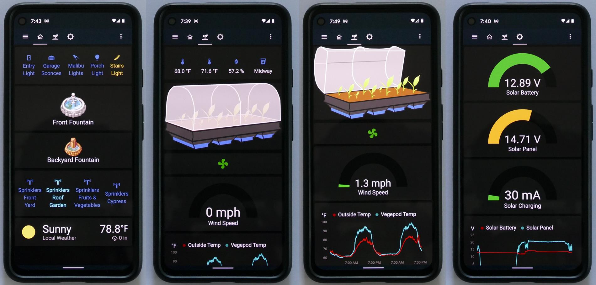
Here’s the free Home Assistant app running on my phone. The first tab lets me control my home lights, fountains and irrigation. The next tab is for the Vegepod. The temperature inside is displayed along with the outside temperature and humidity. The image of the Vegepod will change to reflect the state of the canopy and the water level. The wind speed is displayed below. The green fan spins when the wind sensor spins. The chart below tracks the outside temperature vs the Vegepod temperature. The next tab tracks the solar and battery power. The photo was taken near sunset so the panel voltage is low indicated by the yellow color. The chart below tracks the battery voltage relative to the solar panel voltage. At night time the panel voltage drops to zero but the battery never goes below 12.5 V. And in the morning the battery quickly charges back up. The panel and battery are overkill to power the ESP32, but I do plan on adding a greenhouse in the future that will require more power. At that time I may revisit the code and deploy some of the ESP32’s power saving functions.
 UPDATE: it’s been 3 weeks since my initial planting and I have my first pickling cucumber.

Downloads:
- Vegepod Code (2021-08-10)
- Bracket Sketchup & STL (2021-07-02)
- Eagle schematic and board (2021-07-02)