This tutorial demonstrates how to connect analog sensors to the Raspberry Pi. In particular, I’ll be using a water level detection sensor and a 200 psi pressure sensor.
Unlike Arduinos, the Raspberry Pi doesn’t have an ADC, which stands for Analog to Digital Converter. An ADC measures voltage on a pin and translates it to a number. You can plug an analog sensor directly into an Arduino using the analog ADC pins. The Raspberry Pi requires extra steps.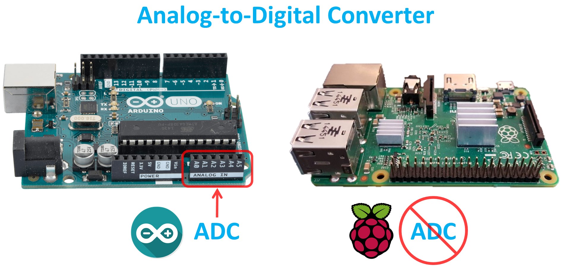
Most devices that you connect to the raspberry PI are either digital or analog. For example, in my DHT-22 tutorial, the temperature humidity sensor is digital. When it’s 25.2 degrees, the DHT22 will send the Pi the number 25.2. At a low level, the communication is ones and zeros or highs and lows but the associated software libraries are usually user friendly and the wiring is minimal. On the other hand, analog sensors signal voltage or resistance depending on the reading. The Koolance SEN-AP006G temperature sensor which I used in my liquid cooled computer monitor, acts as a variable resistor. Its resistance changes as the temperature changes. At 25.2 degrees it has a resistance of about 49 kΩ. The vendor provides a chart so you can look up the corresponding temperature from the resistance. Adding a 10 KΩ fixed resistor creates a voltage divider that would output about .56 V which could be read by an ADC.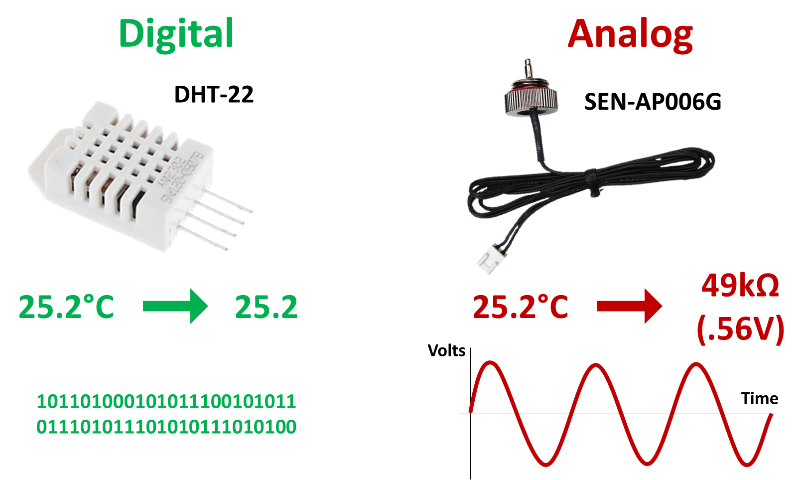
So why use an analog sensor if it’s more work and the Pi doesn’t even have an ADC? Among other reasons, they are often easier to get, some are better suited for specific environments and they may be cheaper. Sometimes there isn’t a digital equivalent.
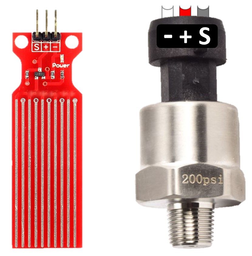
Here’s an analog water level and an analog pressure sensor that I got an eBay. I did search around for comparable digital equivalents, but this is the best I could find at a reasonable price. Both devices output a voltage on the S pin which corresponds to a water level or a pressure value. I’m going to hook them up in my house to warn me if there’s a leak, and to monitor the pressure of the plumbing system.
There are several approaches you can take to connect analog devices to the Pi. You could try an RC charging circuit, but it would only work with sensors that act like resistors such as the Koolance SEN-AP006G. It would not work with the above level and pressure sensors because they output a voltage. The charging circuit counts the program cycles required to charge a capacitor which varies depending on resistance. It works better on microcontrollers than on SoCs. They tend to be inaccurate on the Pi because its operating system can interfere with the counting especially in Python and on multi-core chips found on newer Pi’s. Here’s a sample circuit but I don’t recommend this approach:
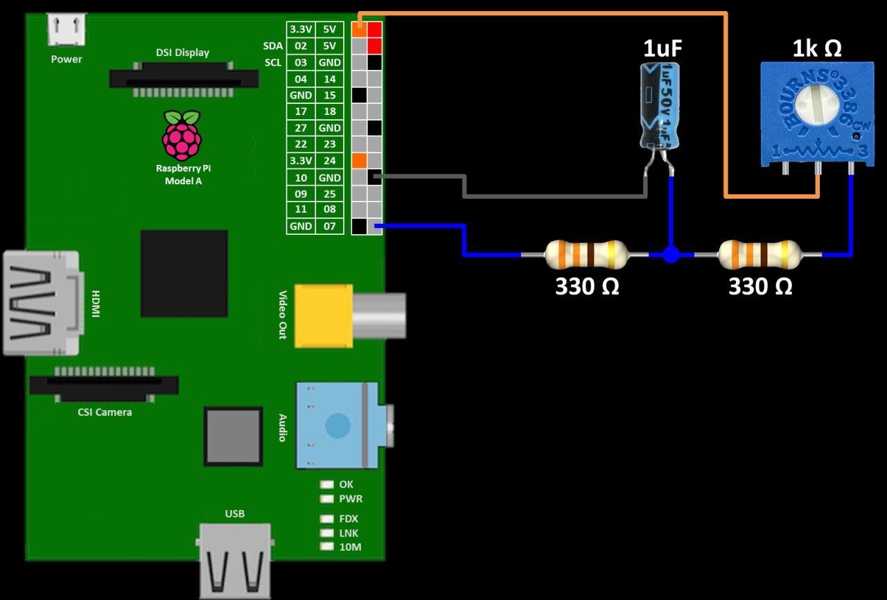
The python code for an RC charging circuit toggles the GPIO monitoring the analog signal between output and input. Then it counts the number of program cycles until GPIO goes high. This number corresponds to a voltage.
import RPi.GPIO as GPIO
from time import sleep

GPIO.setmode(GPIO.BCM)

try:
    while 1:
        count = 0
        GPIO.setup(21, GPIO.OUT)
        GPIO.output(21, GPIO.LOW)
        sleep(0.05)

        GPIO.setup(21, GPIO.IN)
        while(GPIO.input(21) == GPIO.LOW):
            count += 1
        print(count)
        sleep(1)

except KeyboardInterrupt:
    print ("\nCtrl-C pressed.  Program exiting...")
finally:
    GPIO.cleanup() # run on exit
Another solution is to use a microcontroller with an ADC such as an Arduino. It can poll the analog sensors and transmit the results via SPI to the Pi. This is a more advanced technique and I’ve already covered it in my previous video Raspberry Pi AVR Programmer & SPI Tutorial. Therefore this video will focus on dedicated ADC chips such as the MCP3002 and the ADS1115. These devices are inexpensive and very easy to use.
The MCP3002 is a 10-bit resolution SPI analog to digital converter chip with 2 ADC channels.
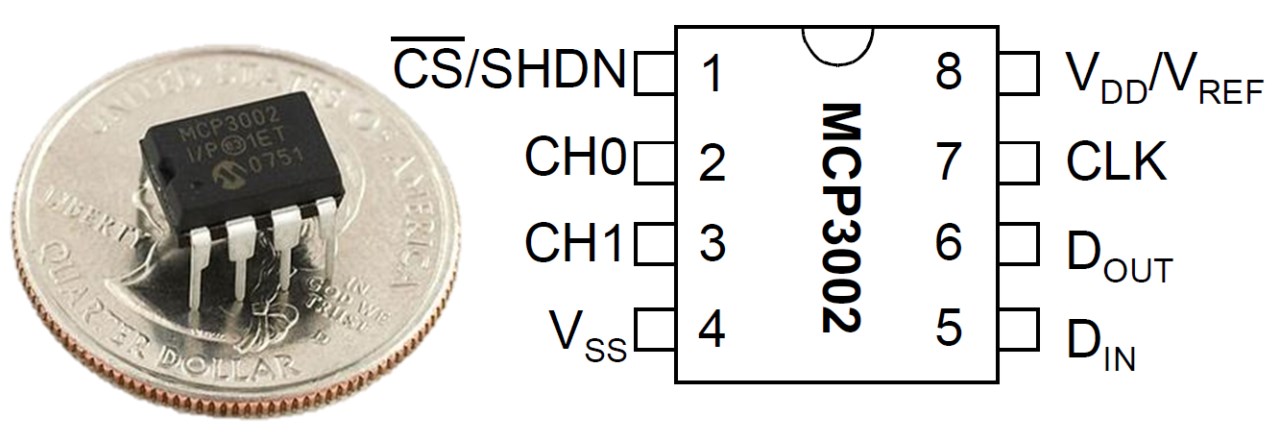
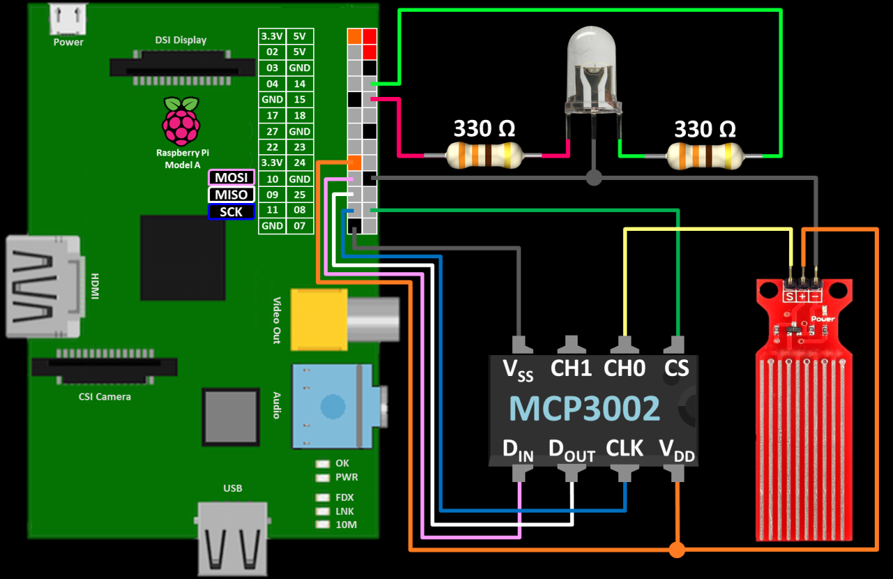
The MCP3002 is connected using Pi’s hardware SPI GPIO pins. DIN goes to GPIO 10 (MOSI: master out slave in). DOUT goes to GPIO 9 (MISO: master in slave out). CLK goes to GPIO 11 (SCK: serial clock). CS goes to GPIO 8 (chip enable zero often called chip select). VDD pin goes to 3.3 V on the Pi and the VSS goes to a ground pin. The water level sensor’s ‘S’ pin is connected to CH0 (ADC channel 0). The plus and minus pins go to 3.3 V and ground respectively. An optional bi-color LED connected in series with 330 Ω resistors to GPIO 14 and 15 provides feedback. The schematic shows a Raspberry Pi A, but this set up will work on any Pi.
For SPI and I2C communication, I recommend you start with a fresh install of the latest version of Raspbian. It comes with all the necessary software libraries installed such as spidev. Also please make sure it is up-to-date:
sudo apt-get update && sudo apt-get upgrade
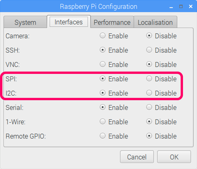
The only software requirements is to enable the SPI and I2C interfaces. From the Pi’s menu click Preferences – Raspberry Pi Configuration . Click the Interfaces tab and enable the SPI interface for the MCP3002 and the I2C interface for the ADS1115. I have more detailed tutorials on both SPI and I2C communication protocols if you’re interested.
Fortunately, the latest version of Raspbian no longer requires super user privileges to access the GPIO pins which simplifies things. Adafruit does make a python library for the MCP3008 which is an 8 channel version of the MCP3002. However, during testing I found that it was not completely compatible. Therefore, I wrote the poll_sensor function below. It reads a specified ADC channel and returns the 10 bit result. The following program polls the sensor every 2 seconds and displays the voltage and 10 bit data value to the shell. A bi-color LED is also used to indicate the presence of water (green: none, yellow: some water, red: more water).
from time import sleep
import RPi.GPIO as GPIO
import spidev
spi = spidev.SpiDev()
spi.open(0, 0)
spi.max_speed_hz = 250000

GPIO.setmode(GPIO.BCM)
GPIO.setup(14, GPIO.OUT)
GPIO.setup(15, GPIO.OUT)

def poll_sensor(channel):
        """Poll MCP3002 ADC
        Args:
            channel (int):  ADC channel 0 or 1
        Returns:
            int: 10 bit value relating voltage 0 to 1023
        """
        assert 0 <= channel <= 1, 'ADC channel must be 0 or 1.'

        # First bit of cbyte is single=1 or diff=0.
        # Second bit is channel 0 or 1
        if channel:
            cbyte = 0b11000000
        else:
            cbyte = 0b10000000

        # Send (Start bit=1, cbyte=sgl/diff & odd/sign & MSBF = 0)
        r = spi.xfer2([1, cbyte, 0])

        # 10 bit value from returned bytes (bits 13-22):
        # XXXXXXXX, XXXX####, ######XX
        return ((r[1] & 31) << 6) + (r[2] >> 2)

try:
    while True:
        channel = 0
        channeldata = poll_sensor(channel)

        voltage = round(((channeldata * 3300) / 1024), 0)
        print('Voltage (mV): {}'.format(voltage))
        print('Data        : {}\n'.format(channeldata))

        if voltage < 50:
            # Green
            GPIO.output(14, GPIO.HIGH)
            GPIO.output(15, GPIO.LOW)
        elif voltage < 1800:
            # Yellow
            GPIO.output(14, GPIO.HIGH)
            GPIO.output(15, GPIO.HIGH)
        else:
            # Red
            GPIO.output(14, GPIO.LOW)
            GPIO.output(15, GPIO.HIGH)
        sleep(2)
finally:                # run on exit
    spi.close()         # clean up
    GPIO.cleanup()
    print "\n All cleaned up."
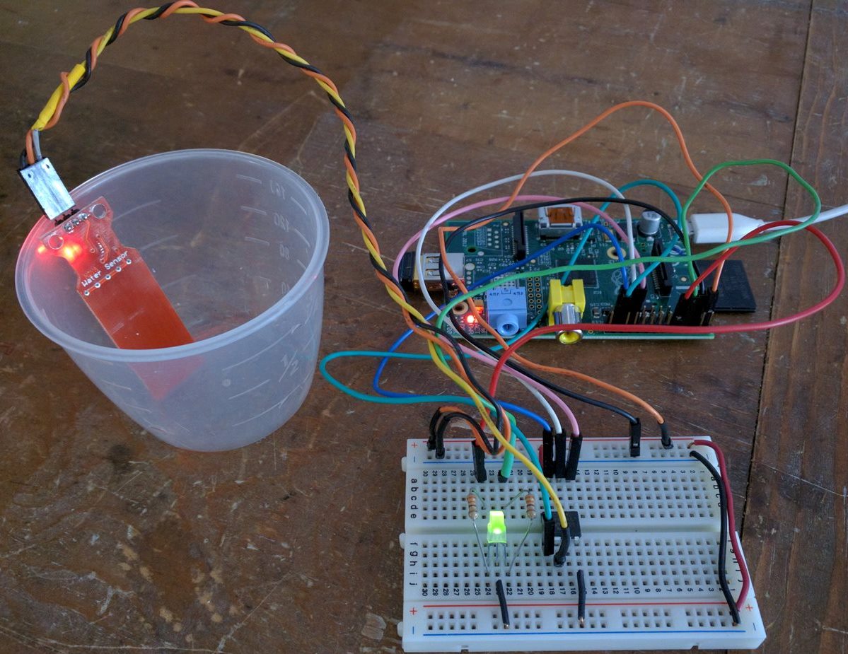
Here’s the water detection circuit on the breadboard.
I found that the water level sensor is not very accurate, but it is good for water detection. It would also be possible to use a water pressure sensor to measure water level by monitoring the pressure at the bottom of a water tank. I’m using a 200 psi sensor to measure my household plumbing pressure which can reach 180 psi. For water level, you would use a much lower pressure sensor.
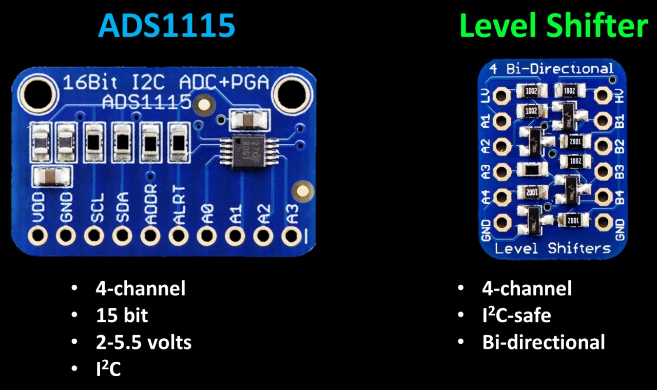
For the pressure sensor hook up, I’ll use an ADS1115 breakout board. It’s a 4 channel I2C ADC. It’s 15 bit resolution is more accurate than the 10 bit MCP3002. It supports power supplies from 2 to 5.5 V which works well because the pressure sensor runs at 5 V. I’ll also use an Adafruit I2C-safe level shifter between the 3.3 V Pi and the ADS1115 running at 5 V. In theory, I could hook up the ADS1115 without a level shifter for the I2C lines but it would be out of spec and I would probably have to desolder the pull-up resistors from the breakout board. Hence, I feel it’s safer and more reliable to use the inexpensive shifter. You can damage the Pi by exposing a GPIO pin to 5 volts.
The ADS1115 is connected to the Pi using the I2C lines SDA (GPIO2) and SCL (GPIO3). The Pi’s SDA and SCL connect to the lower voltage side of the level shifter on ports A1 and A2. The ADS1115’s SDA and SCL connect to the higher voltage side of the shifter on corresponding ports B1 and B2. The shifter resides between the Pi and the ADS1115 and shifts the voltages appropriately to protect the Pi and ensure reliability. The LV (lower voltage) pin on the shifter is connected a 3.3 V pin on the Pi. The shifer’s HV (higher voltage) pin and the ADS1115’s VDD are connected to a 5 V pin on the Pi. All 3 boards share a ground. The pressure sensor plus pin goes to 5 V and the minus pin goes to ground. The ‘S’ pin is connected to A0 on the ADS1115 which is ADC channel zero. An LCD display is used for visual feedback. For more information on using LCD displays with the Pi, please see my LCD display tutorial.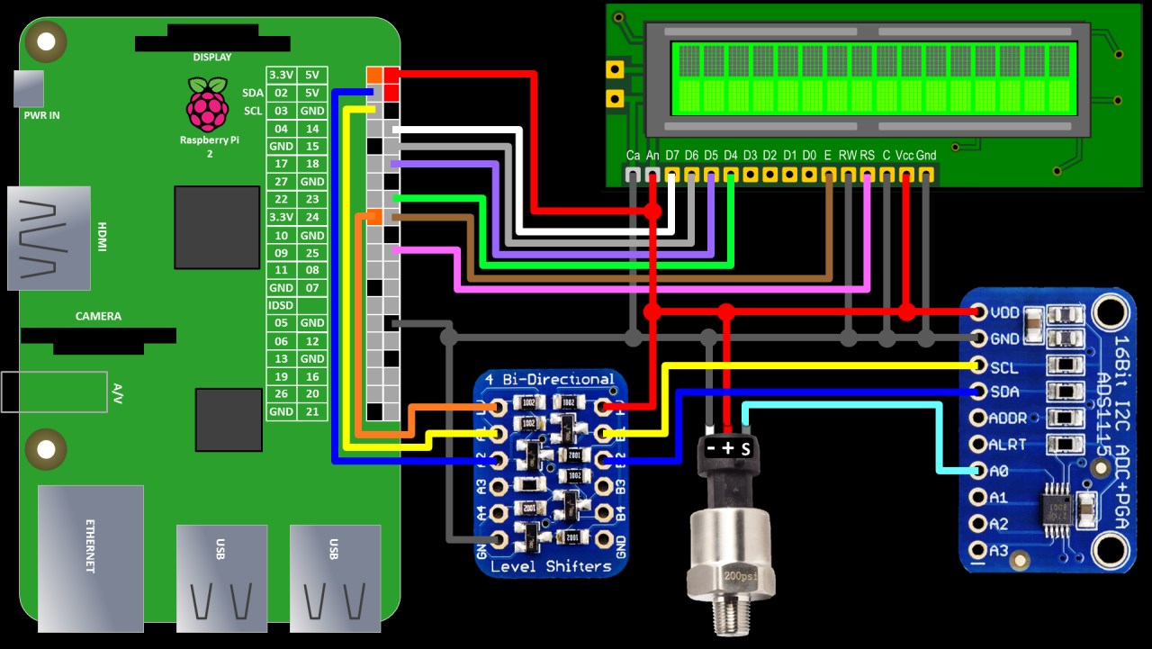
Adafruit provides a python library for the ADS1115 that works great and is easy to use. The Adafruit–ads1x15 library is easily installed using pip.
sudo pip install adafruit-ads1x15
Adafruit also provides a great python library for LCD displays which I have used in several of my projects. It’s now even easier to install. Again just use pip to install the Char LCD library.
sudo pip install adafruit-charlcd
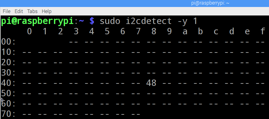
Next i2cdetect is used to ensure the wiring is OK and to obtain the hex address for the ADS1115. The 1 argument designates bus 1. On older Pi’s this could be zero.
sudo i2cdetect -y 1
The matrix shows the ADS1115 is connected correctly on hex address 0x48.
The python code imports the Adafruit_CharLCD libary and instantiates and lcd specifying the GPIO pins and display size. The Adafruit_ADS1x15 library is imported and an adc is instantiated specifying the hex address 0x48 obtained from the i2cdetect utility and bus number 1. The gain is set to 2/3 which is for reading voltages up to 6.144 V. Table 3 in the datasheet has different gain values if you are reading lower voltages. Please note that you should never allow voltages higher than the VDD pin to come in contact with an ADC channel. Since the ADS1115 is running at 5 V, it could be damaged by a voltage on one of the ADC channels exceeding 5.3 V. The main loop polls the sensor and displays the results to the LCD display.
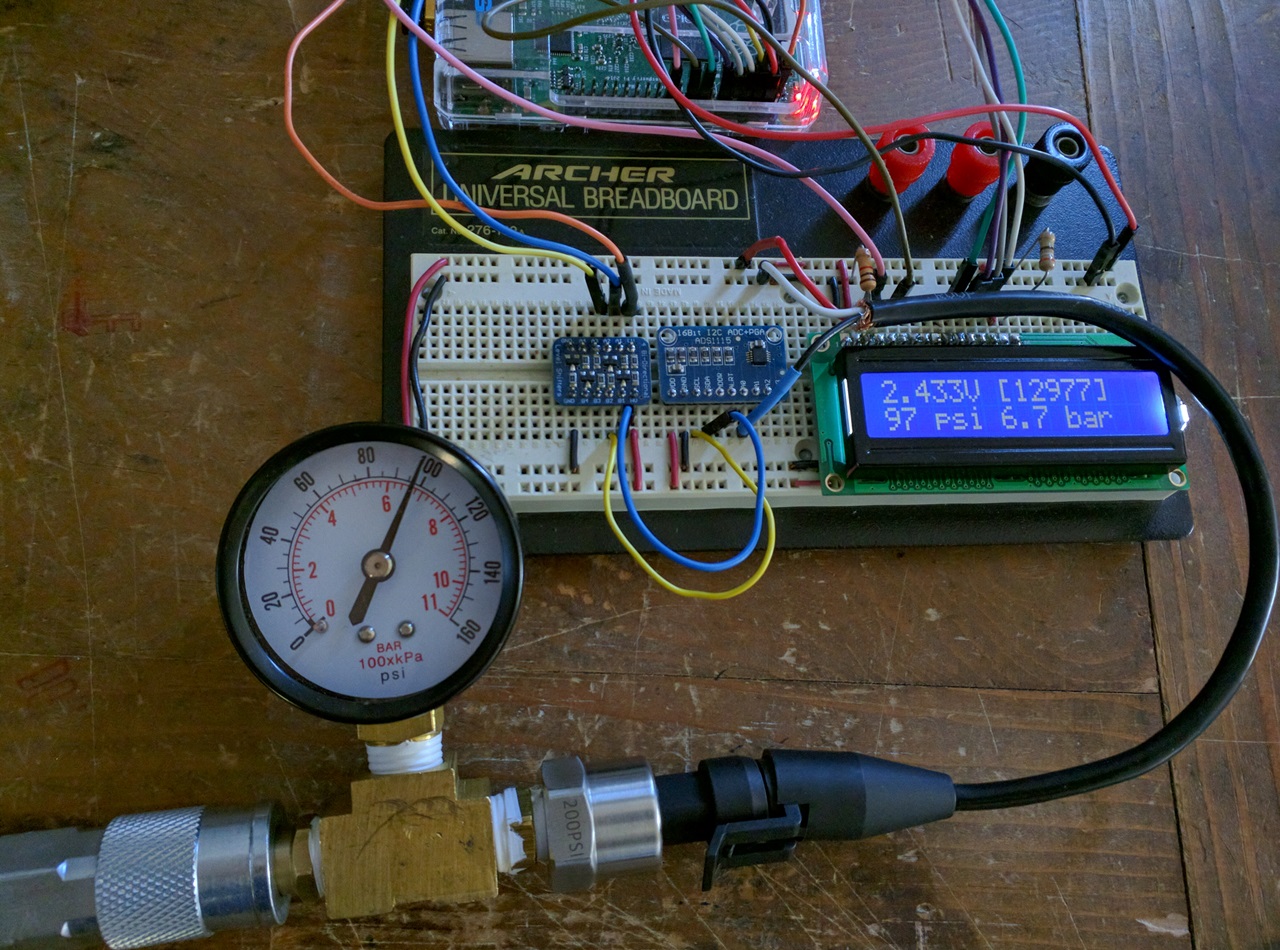
from time import sleep
from Adafruit_CharLCD import Adafruit_CharLCD
lcd = Adafruit_CharLCD(rs=25, en=24, d4=23, d5=18, d6=15, d7=14,
                       cols=16, lines=2)

import Adafruit_ADS1x15
adc = Adafruit_ADS1x15.ADS1115(address=0x48, busnum=1)

# Gain = 2/3 for reading voltages from 0 to 6.144V.
# See table 3 in ADS1115 datasheet
GAIN = 2/3

# Main loop.
while 1:
    value = [0]
    # Read ADC channel 0
    value[0] = adc.read_adc(0, gain=GAIN)
    # Ratio of 15 bit value to max volts determines volts
    volts = value[0] / 32767.0 * 6.144
    # Tests shows linear relationship between psi & voltage:
    psi = 50.0 * volts - 25.0
    # Bar conversion
    bar = psi * 0.0689475729

    lcd.clear()
    lcd.message("{0:0.3f}V [{1}]".format(volts, value[0]))
    lcd.message("\n{0:0.0f} psi {1:0.1f} bar".format(psi, bar))

    sleep(1)
Voltage is calculated from the 15 bit returned value by dividing by 32,767 for 10 bit resolution and then multiplying by 6.144 for the maximum gain voltage. When I first tested the sensor I determined that the relationship between psi and voltage was linear and determined the line equation using y=mx+b. There is a great online line equation calculator on WebMath that automatically solves for the line equation using 2 points. It provides the answer and a complete explanation of how to solve for the equation. For this sensor, psi = 50 x volts – 25. Plugging in the returned voltage returns the psi reading. The display shows voltage, the data reading, psi and bar.
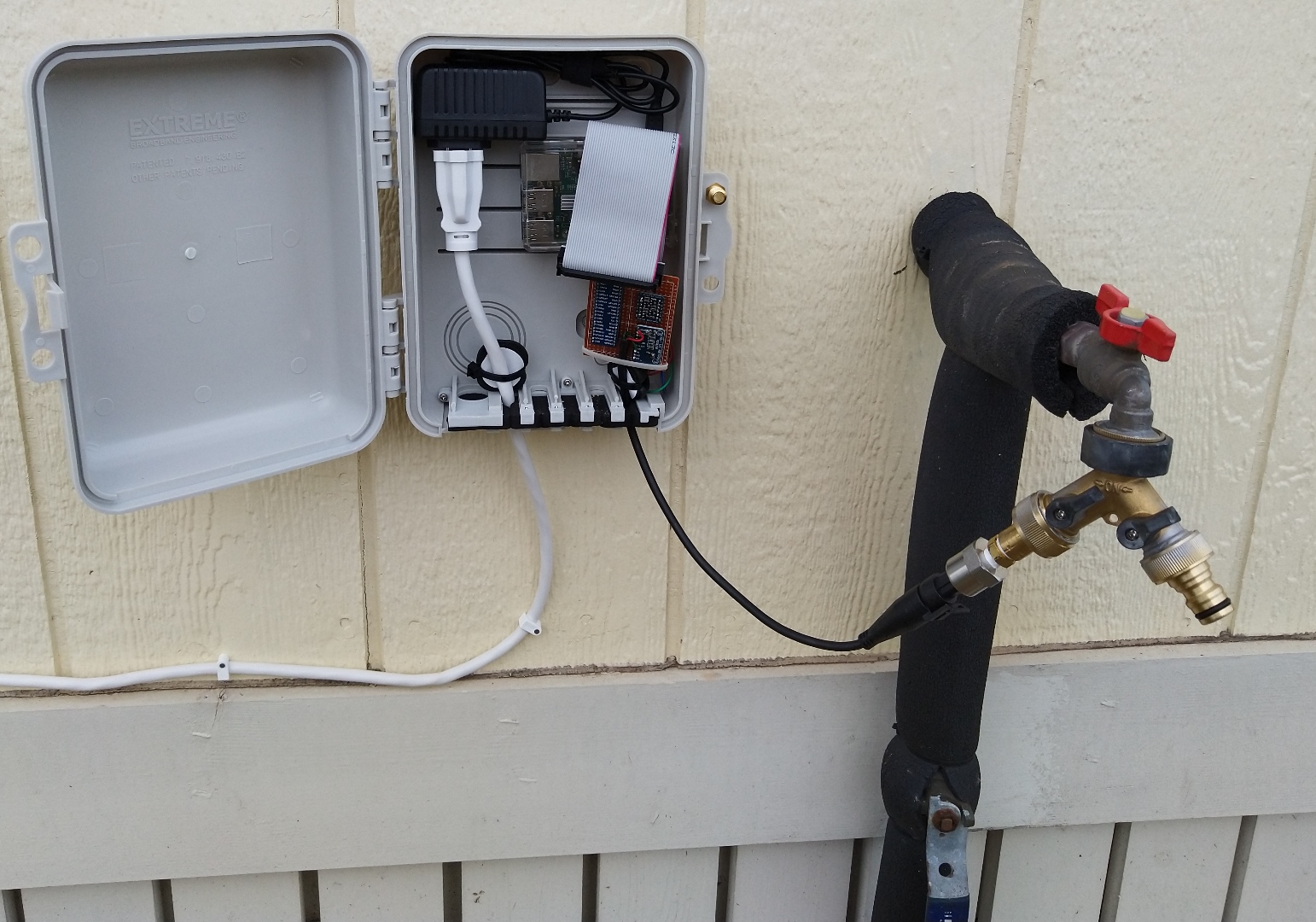
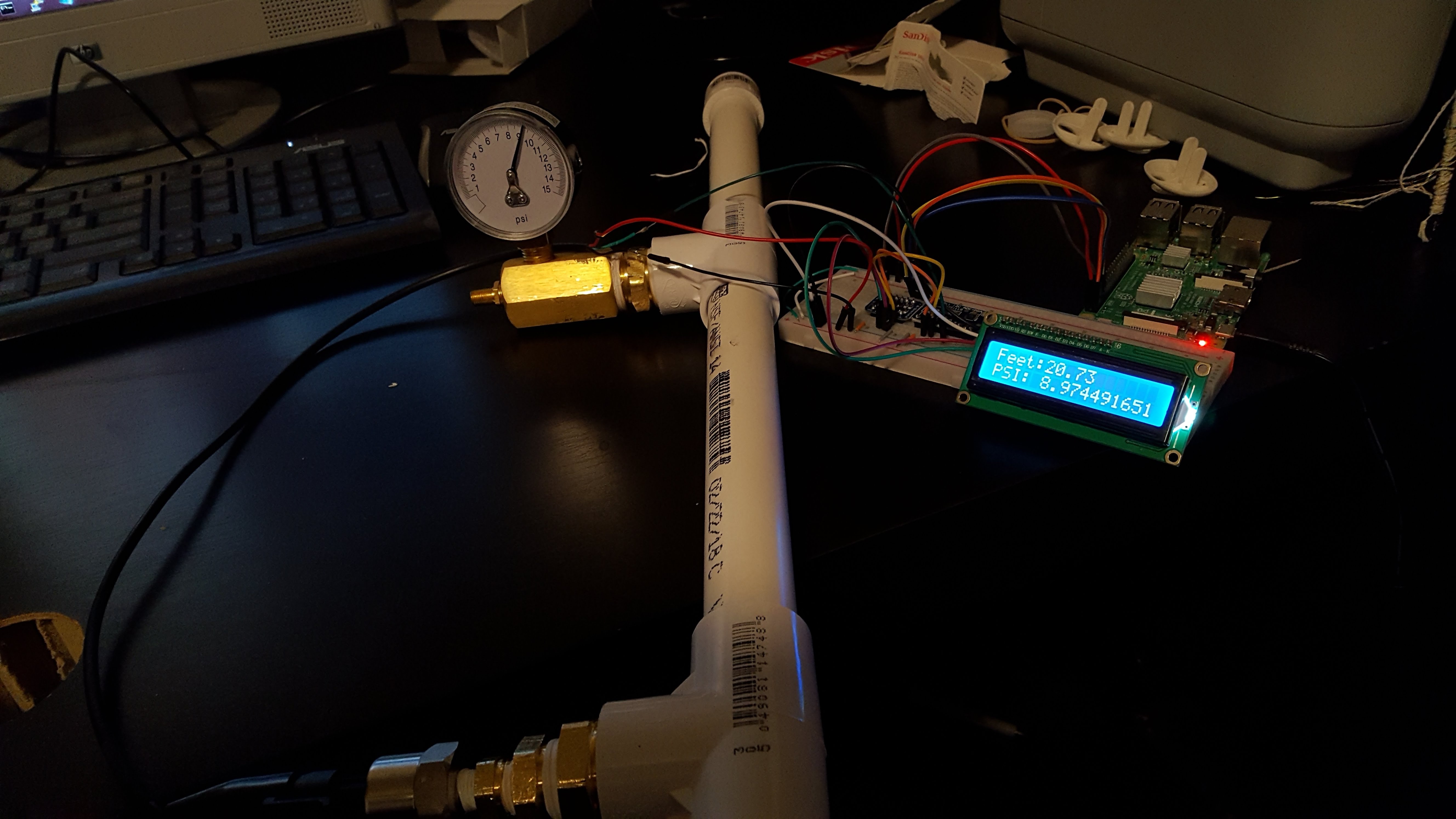
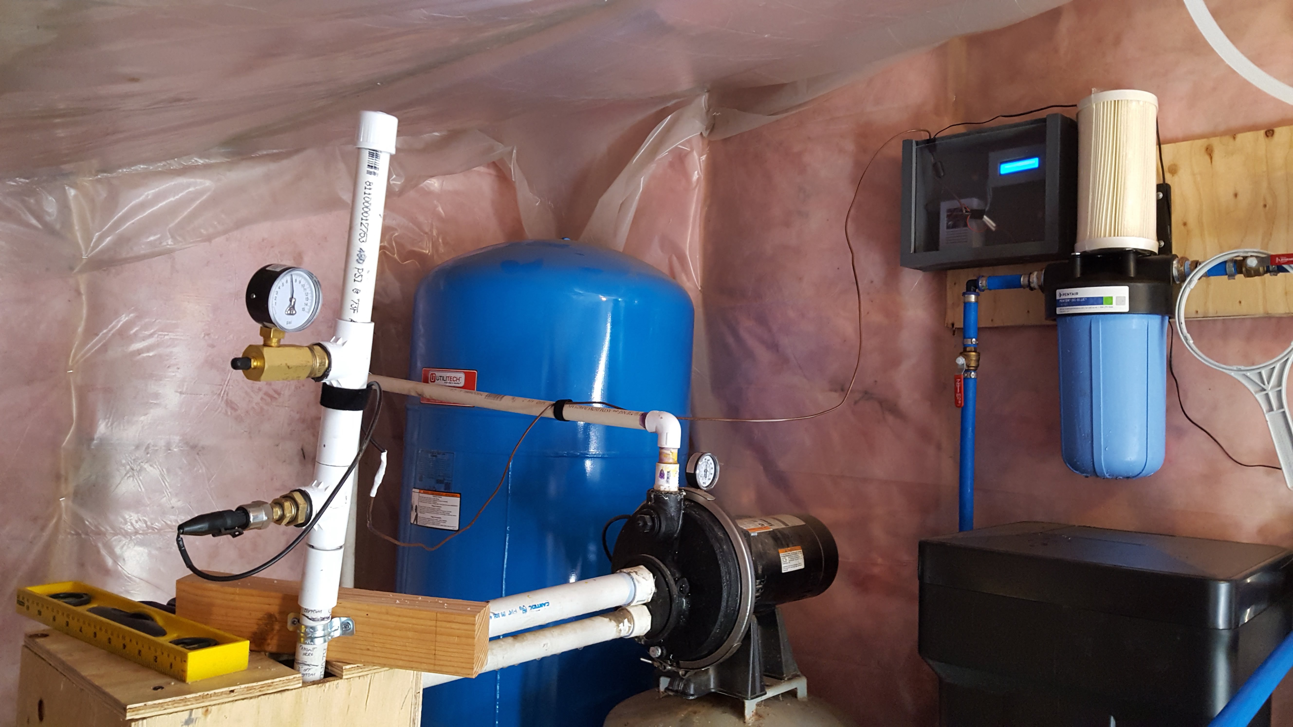
A viewer named Robert sent me some pics of a well monitoring system he designed and built using this tutorial. He sunk a pipe into his underground well and is using an analog pressure sensor to measure the air pressure of the pipe. A Raspberry Pi uses the pressure readings to calculate water level, usage and generate reports.
Another inspired viewer named Juan sent me a pic of a Raspberry Pi web server he created to track the city water pressure.