
This tutorial demonstrates how to build a Raspberry Pi audio spectrum analyzer using a bi-color LED matrix and a Holtek HT16K33 which is a very powerful I2C LED controller driver and matrix key scanner.
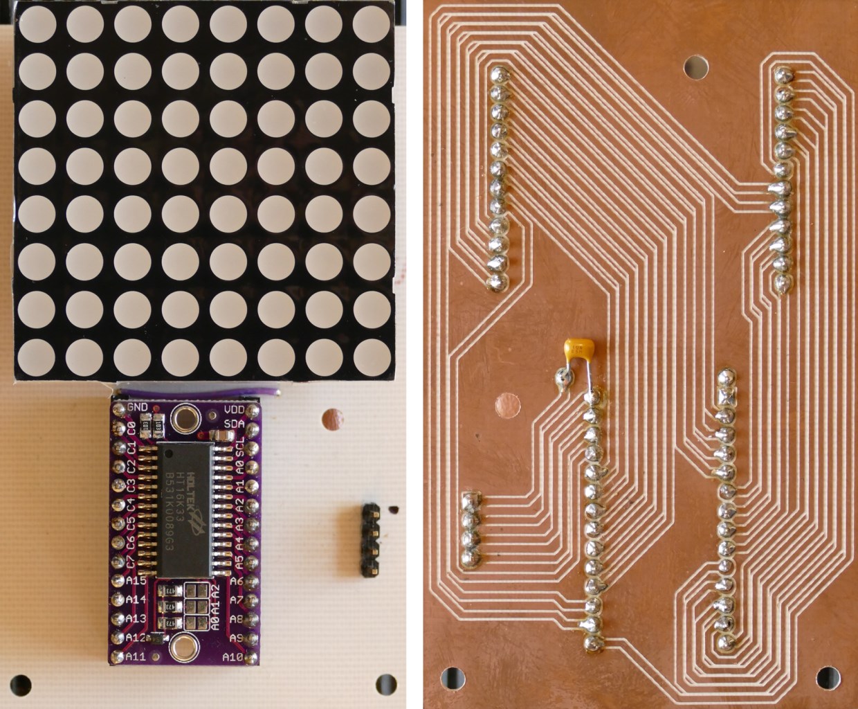
Here’s an HT16K33 breakout board, I picked up on eBay. They are also available from Adafruit. This inexpensive board adds a ton of capability to the Pi and is very intuitive and easy to set up.
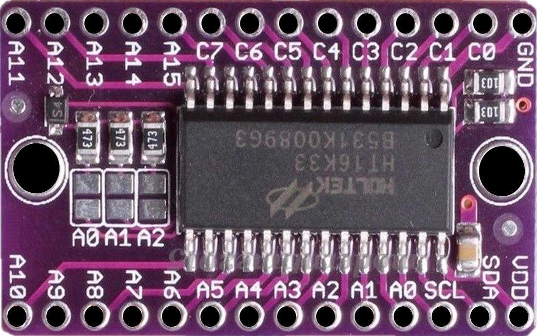
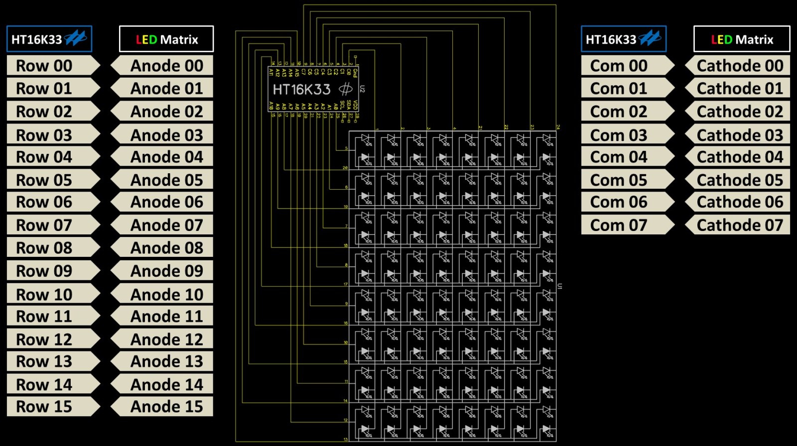
It has 16 row pins (A0 to A15) and 8 column pins (C0 to C7). The rows connect to LED anodes and the columns connect to cathodes. It uses multiplexing to light up 8 groups of 16 LED’s. Check out my 7 segment LED tutorial for more information on multiplexing. The chip can drive 128 LED’s and it only requires 2 GPIO pins on the Pi. Here are some examples of the types of displays you can use:
- • A 16×8 LED matrix
- • Eight 16 segment alphanumeric LED displays
- • Sixteen 7 segment numeric displays which have 8 LED’s if you include the decimal
- • A dual color 8×8 LED matrix
Here’s a SparkFun 2″ dual color LED matrix. It will be used for the spectrum analyzer’s display. It has 64 bi color LED’s — green and red. If you turn both LED’s on simultaneously you get yellow too. It’s a perfect match for the HT16K33 because it has 16 anodes for the 16 rows (8 red plus 8 green) and 8 cathodes for the 8 columns.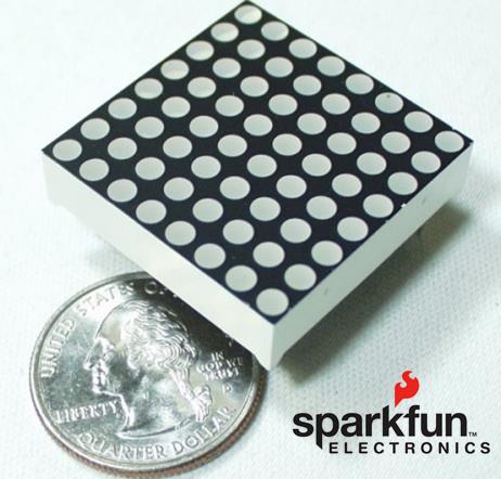
The SparkFun display is very bright but does use a bit of power. The HT16K33 can run at 3.3 V but that was not powerful enough to light up this bi-color matrix properly. It needs to be run at 5 V. It’s prudent to use a level shifter to protect the Pi’s 3.3 V data lines when working with 5 V devices. It is also important to use a level shifter that supports I2C. I’m using an Adafruit I2C safe level shifter with 4 BSS138 FETs and 10K pull-ups.
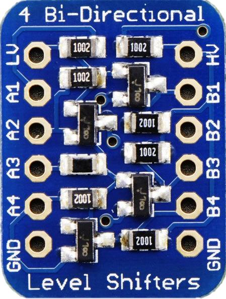
This is one of the few level shifters that works well with I2C. It has 4 channels for shifting voltages between 1.8 V and 10 V. We’ll use 2 channels to shift SDA and SCL between the 3.3 V Raspberry Pi and the 5 V HT16K33.
For the wiring, a 5 V pin from the Pi is connected to the HV pin on the level shifter and to the VDD pin on the HT16K33. All three devices share grounds. A Pi 3.3 V pin goes to the LV pin on the level shifter. The Pi’s SDA & SCL (GPIO 2 & 3) connect to A1 and A2 on the shifter. The HT16K33 SDA and SCL pins go to B1 and B2. That’s all it takes to connect the HT16K33.
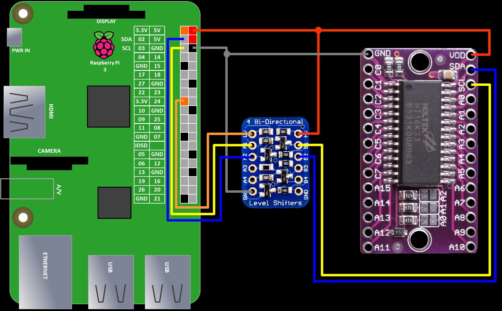
The shifter sits between the data lines and performs bi-directional logic level voltage conversion between the A pins and the corresponding B pins. It also serves to protect the Pi’s GPIO pins which could be damaged if exposed directly to 5 V.
Connecting the HT16K33 to the dual color LED matrix is straight forward. The 16 row pins from the chip connect to the 16 anode pins on the matrix. And the 8 column pins connect to the 8 cathode pins.
The 24 connections is a lot of jumpers so I milled an adapter board. Female headers are used so the matrix and breakout board can easily be removed. The HT16K33 datasheet recommends a 0.1 μF capacitor which I soldered to the adapter between Vdd and ground. It’s probably not necessary because the breakout board already has a cap. You can download the adapter board plans below.
 UPDATE: There have been breaking changes to the code. Please check out the update.
I recommend that you use a clean install of the latest version of Raspbian and use apt-get to insure it is updated and upgraded.
sudo apt-get update && sudo apt-get upgrade
Python DEV, Python Imaging and Python SMBUS are required.
sudo apt-get install python-dev python-imaging python-smbus
The Python ALSA Audio library is required to provide audio playback.
sudo apt-get install python-alsaaudio
Use Git clone to download and install the Adafruit Python GPIO library. It’s used by the other Adafruit libraries to interface with the Pi’s GPIO.
cd~
git clone https://github.com/adafruit/Adafruit_Python_GPIO.git
cd Adafruit_Python_GPIO
sudo python setup.py install
Repeat for the Adafruit Python LED backpack library. It provides lots of code to control LED displays via the HT16K33.
cd~
git clone https://github.com/adafruit/Adafruit_Python_LED_Backpack.git
cd Adafruit_Python_LED_Backpack
sudo python setup.py install
Use the Raspberry Pi Software Configuration Tool to enable I2C.
sudo raspi-config
- 1. Select Advanced Options
- 2. Select I2c
- 3. Click Yes to enable the interface
- 4. Click OK and Finish to exit
- 5. Reboot the Pi (Required)
After rebooting, open Idle with GKSU because super-user privileges are required when working with the GPIO pins. (Update: super-user privileges are no longer required for GPIO access with the latest version of Raspbian.) The Idle IDE no longer comes with the latest version of Raspbian. It has been replaced by the Thonny Python IDE.
/usr/bin/gksu -u root idle
The program starts by importing the ALSA python wrapper, the python Wave library, Unpack from Struct, NumPy and the Bi Color Matrix 8×8 class from the Adafruit LED backpack library.
import alsaaudio as aa
import wave
from struct import unpack
import numpy as np
from Adafruit_LED_Backpack import BicolorMatrix8x8
A bicolor 8×8 matrix display is instantiated. Begin initializes the display. The display is cleared and the brightness is set to seven. You can pick any value from 0 which is dim to 15 full brightness.
# Create BicolorMatrix display instance with default settings
display = BicolorMatrix8x8.BicolorMatrix8x8()
display.begin()
display.clear()
display.set_brightness(7)
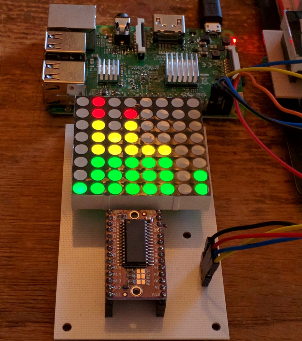
A spectrum list determines the color thresholds for frequencies. 1 is green, 3 is yellow and 2 is red. The lower 3 LED rows will be green, then 3 yellow and the top 2 red. Matrix holds the current frequency levels. Power is for the amplitude spectrum. Weighting scales the frequency data to the display.
spectrum  = [1,1,1,3,3,3,2,2]
matrix    = [0,0,0,0,0,0,0,0]
power     = []
weighting = [2,8,8,16,16,32,32,64]
The audio set up is all boiler plate code. A wave music file which already exists in my Pi’s music folder is opened. The sample rate and number of channels is determined. Chunk sets the number of frames of audio to read at a time as a string of bytes. It should be a multiple of 8.
# Audio setup
wavfile = wave.open('/home/pi/Music/Secret Agent.wav','r')
sample_rate = wavfile.getframerate()
no_channels = wavfile.getnchannels()
chunk       = 4096 # Use a multiple of 8
An ALSA audio output is set up. This pipes the music to PI’s audio outputs so we can hear it.
# ALSA
output = aa.PCM(aa.PCM_PLAYBACK, aa.PCM_NORMAL)
output.setchannels(no_channels)
output.setrate(sample_rate)
output.setformat(aa.PCM_FORMAT_S16_LE)
output.setperiodsize(chunk)
I didn’t write the next 2 functions piff() which returns a power array index corresponding to a particular frequency and caculate_levels() which returns a list of audio frequency amplitudes to display. I derived them from Juliana Pena’s blog.
Unpack converts the raw audio data to a format compatible to create a NumPy array. I’m not going to go into the FFT math because NumPy does the heavy lifting for you. Basically NumPy applies a fast Fourier transform to the audio data to extract the average amplitude levels for the 8 specified frequency ranges measured in hertz. The frequency data is formatted for the matrix display and returned.
# Return power array index corresponding to a particular frequency
def piff(val):
   return int(2*chunk*val/sample_rate)

def calculate_levels(data, chunk,sample_rate):
   global matrix

   # Convert raw data (ASCII string) to numpy array
   data = unpack("%dh"%(len(data)/2),data)
   data = np.array(data, dtype='h')

   # Apply FFT - real data
   fourier=np.fft.rfft(data)
   # Remove last element in array to make it the same size as chunk
   fourier=np.delete(fourier,len(fourier)-1)
   # Find average 'amplitude' for specific frequency ranges in Hz
   power = np.abs(fourier)
   matrix[0]= int(np.mean(power[piff(0)    :piff(156):1]))
   matrix[1]= int(np.mean(power[piff(156)  :piff(313):1]))
   matrix[2]= int(np.mean(power[piff(313)  :piff(625):1]))
   matrix[3]= int(np.mean(power[piff(625)  :piff(1250):1]))
   matrix[4]= int(np.mean(power[piff(1250) :piff(2500):1]))
   matrix[5]= int(np.mean(power[piff(2500) :piff(5000):1]))
   matrix[6]= int(np.mean(power[piff(5000) :piff(10000):1]))
   matrix[7]= int(np.mean(power[piff(10000):piff(20000):1]))

   # Tidy up column values for the LED matrix
   matrix=np.divide(np.multiply(matrix,weighting),1000000)
   # Set floor at 0 and ceiling at 8 for LED matrix
   matrix=matrix.clip(0,8)
   return matrix
The main program loop reads the wave file audio data 1 chunk at a time and continues until the end of the song. The ALSA output.write() plays the music. The calculate_levels() function is called to generate the audio frequencies spectrum. The LED matrix display is cleared. For Y loops through the 8 specified frequencies. For X loops through the amplitudes. The Adafruit display.set_pixel() draws a pixel at the XY location on the led matrix. LED color is determined by spectrum[x] – green, yellow or red. Nothing is actually displayed on the LED matrix until write_display() is called which presents all the pixel data to the display. The Wave library wavfile.readframes() gets the next chunk of audio data and the loop repeats.
# Start reading .wav file
data = wavfile.readframes(chunk)
# Loop while audio data present
while data!='':
   output.write(data)
   matrix=calculate_levels(data, chunk,sample_rate)
   display.clear()
   for y in range (0,8):
       for x in range(0, matrix[y]):
           display.set_pixel(x, y, spectrum[x])
   display.write_display()
   data = wavfile.readframes(chunk)
When you run the code, the music starts and the matrix shows the audio spectrum.
 Microphone Update: I received a couple of questions regarding using a mic for the input source. This turns out to be a simple modification. PyAudio is used instead of the Python Wave library. It can be installed with apt install:
sudo apt install python3-pyaudio
The Pi doesn’t have a microphone jack or line input so I’m using an old USB Logitech QuickCam Pro 3000 which is plug-and-play with the Pi. You will need to determine the index of your audio device. I used the following function:
def list_devices():
    # List all audio input devices
    p = pyaudio.PyAudio()
    i = 0
    n = p.get_device_count()
    while i < n:
        dev = p.get_device_info_by_index(i)
        if dev['maxInputChannels'] > 0:
           print(str(i)+'. '+dev['name'])
        i += 1
Here’s the code to instantiate PyAudio and open a stream. The chunk size takes some trial and error. A lower number gives you a more responsive display but if it’s too low the program will crash with the an overflow error. Device is the index of my microphone obtained with the list_devices() function above.
import pyaudio
no_channels = 1
sample_rate = 44100
chunk = 3072
device = 2

p = pyaudio.PyAudio()
stream = p.open(format = pyaudio.paInt16,
                channels = no_channels,
                rate = sample_rate,
                input = True,
                frames_per_buffer = chunk,
                input_device_index = device)
You can download the revised microphone code below.
 CircuitPython Update
The Alsa Audio library should be installed for Python3
sudo apt install python3-alsaaudio
The Adafruit Blinka library needs to be installed. Here are detailed instructions. If you are using Raspberry Pi OS Bookworm or higher then you will need to create a virtual environment.
sudo apt install python3-venv
python3 -m venv env --system-site-packages
source env/bin/activate
Adafruit provides an automated install script to facilitate the setup of Blinka.
cd ~
pip3 install --upgrade adafruit-python-shell
wget https://raw.githubusercontent.com/adafruit/Raspberry-Pi-Installer-Scripts/master/raspi-blinka.py
sudo -E env PATH=$PATH python3 raspi-blinka.py
A reboot will be required after you run the script. Every time the Pi is rebooted you will need to reactivate the virtual environment.
source env/bin/activate
The Adafruit CircuitPython HT16K33 library will be used to control the matrix. It is installed using pip3.
pip3 install adafruit-circuitpython-ht16k33
The revised CircuitPython code is available to download below.
Downloads
Python Code v.1.0 – 08/19/2016
Python Code (Microphone Version) v.1.0 – 08/25/2016
Python Code (CircuitPython) v.2.0 – 05/31/2024
Python Code (Microphone / CircuitPython) v.2.0 – 05/31/2024
Adapter board DipTrace & FlatCAM files