
This tutorial demonstrates how to use a Raspberry Pi to program AVR chips and how to use SPI protocol in Python which can be used to communicate between a Pi and an AVR or any other device that supports SPI.
My projects section contains many AVR based projects. AVR chips such as the Atmel ATtiny or ATmega are powerful 8 bit microcontrollers. They can often be purchased on eBay for a couple of dollars. They are a great solution for controlling projects because they are small, inexpensive, fast, can run off batteries and can interface with just about any DIY electronics including the Pi. Futhermore, there are times when there is no Pi driver available for a component such as a graphic display, but an AVR driver is available. Also some devices such as multi-digit LED displays can consume too much of the Pi’s CPU resources. Offloading the operations to an AVR can reduce the load and is often cheaper than a dedicated LCD driver IC.
I’m better at software than hardware. Often a single AVR can replace a complicated electrical circuit with multiple components. AVR chips run code that can be compiled from basic, C and assembly language. The code is usually written on a PC and then compiled and uploaded to the AVR with a programmer. Adafruit sells a USB programmer kit that works well. I also have a DIY USB programmer that I developed. Of course, you don’t need to buy or make a programmer if you have a Raspberry Pi, because it can do the job.
For this tutorial, I’ll be using an ATtiny24 AVR chip.
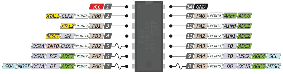
It is a 14 pin DIP package so it’s breadboard friendly. 12 pins can be used as inputs or outputs similar to the PI’s GPIO. Eight of these pins are hardware ADC which means they support analog to digital conversion. You can use them to measure voltage or read analog devices (a feature missing from the pi). This AVR can run at a voltage between 1.8 and 5.5 V, so it can be powered by a Pi. It can be clocked up to 20 MHz and it has a Universal Serial Interface or USI which is compatible with the PI’s SPI.
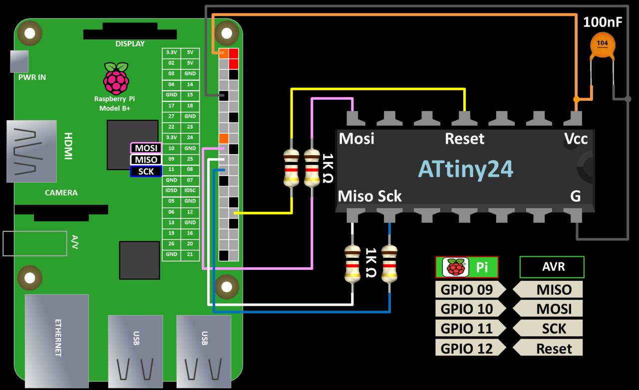
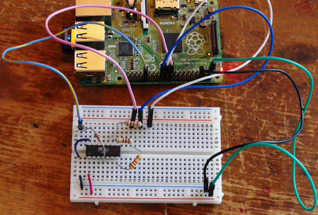
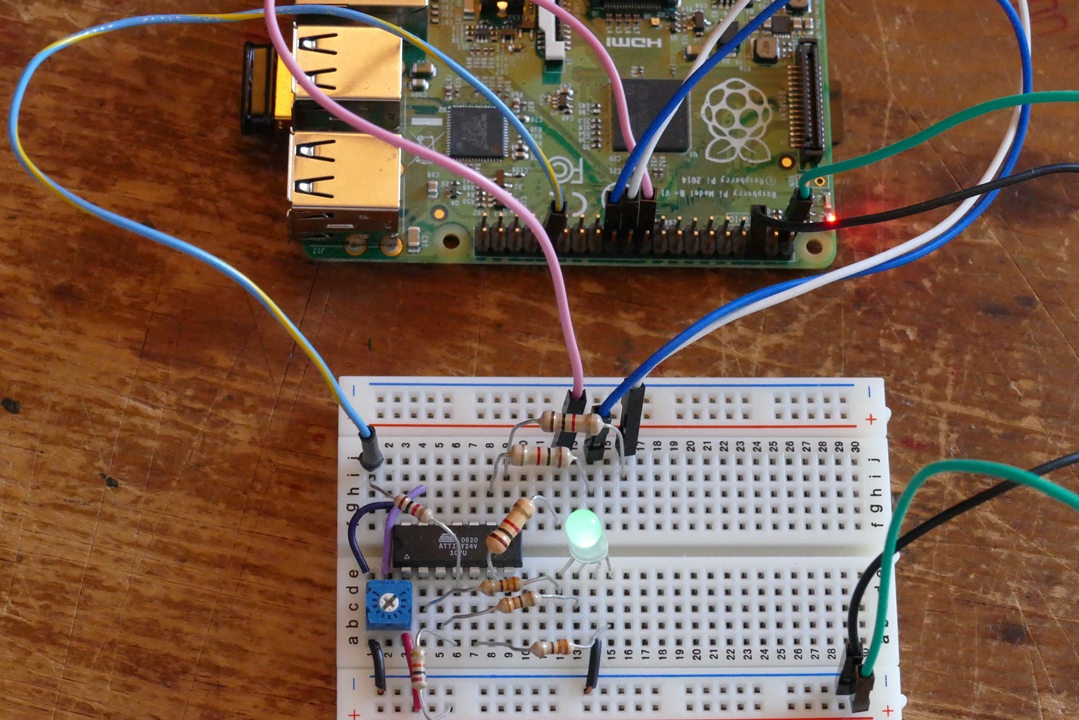
The wiring to program an AVR from the Pi is very simple. There are 4 GPIO connections. The MOSI, MISO and Serial Clock pins of the Pi and the AVR will be connected together and an additional Pi pin will control the AVR Reset. 1 KΩ resistors are placed in series with each connection to limit the current. The Pi will also provide 3.3 V power and ground. If you want to run the AVR at a higher voltage then you would need to use voltage level shifters on all the data lines because the Pi’s GPIO pins cannot tolerate more than 3.3 V. AVR’s should have a low ESR capacitor (10 nF to 100 nF) as close as possible to each VCC/ground pair on the chip.
A popular programming software for AVR chips is called AVRDude.
 It is no longer necessary to manually install avrdude (as shown in the video). Just use apt-get install:
sudo apt-get install avrdude
Open the AVRDude configuration file for editing after installation (location different from video.)
sudo nano /etc/avrdude.conf
In Nano, use ctrl-w to search for linuxgpio. This is the section that controls the GPIO pins used for programming. The section needs to be uncommented. Set the MOSI, MISO and SCK entries to the GPIO pins on the Pi. For Reset, you can use any GPIO pin. I’m using 12.
programmer
  id    = "linuxgpio";
  desc  = "Use the Linux sysfs interface to bitbang GPIO lines";
  type  = "linuxgpio";
  reset = 12;
  sck   = 11;
  mosi  = 10;
  miso  = 9;
;
Just for the record, AVRDude is not implementing true SPI communication. Instead it is bitbanging the GPIO lines. A good way to test that everything is set up correctly is to enter AVRDude terminal mode (location different from video.)
sudo /usr/bin/avrdude -p t24 -c linuxgpio -v -t
The -p switch specifies the AVR part (t24 for ATtiny24). The -c switch specifies the programmer which is linuxgpio to use the Pi’s GPIO. The -v is for verbose and -t is for terminal. Once, in terminal you can issue commands such as erase to clear the AVR chip or sig for the AVR device signature. Quit is used to exit terminal mode.
AVRDude supports programming many different chips. You can get a list of all supported part numbers with the following command:
avrdude -c avrisp
I wrote a simple AVR test program in BascomAVR basic that allows you to control the color of an RGB LED with a potentiometer. Here is the main loop from the basic program:
Do
   W = Getadc(0)
   'Lower 10 bit ADC to 3 bit resolution (8 values)
   Shift W , Right , 7
   'Look up RGB pulse values
   red_pulse = LookUp(W, RedData)
   green_pulse = LookUp(W, GreenData)
   blue_pulse = LookUp(W, BlueData)
   'Generate RGB pulses
   If red_pulse > 0 then Pulseout PortB , R , red_pulse
   Waitms 1
   If green_pulse > 0 then Pulseout PortB , G , green_pulse
   Waitms 1
   If blue_pulse > 0 then Pulseout PortB , B , blue_pulse
   Waitms 1
Loop
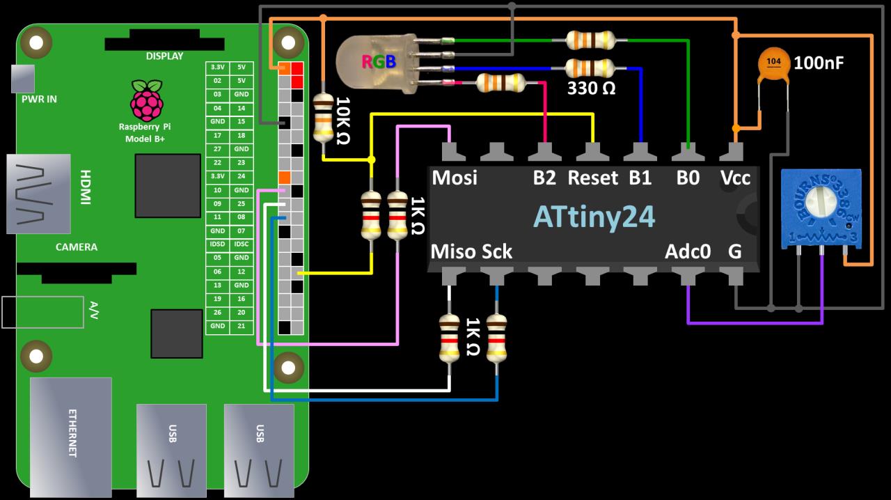
The program polls ADC0 on the AVR which reads the voltage of a potentiometer. The value is shifted to 3 bit so there are 8 possible values which are translated into 8 possible colors. The RGB LED is then illuminated to the selected color using PWM.
The AVR programming lines (MOSI, MISO, SCK, Reset) can be left hooked up to the Pi although it’s not necessary once the chip is programmed. You just need to provide power. The pot is connected to AVR pin 13 which is ADC0. The pot dial will vary the voltage to pin 13 between 0 and 3.3 V. The RGB LED is connected to AVR pins 2, 3 & 5 which are port B pins 0 – 2. 330 Ω resistors are placed in series to limit the current. The state of the pins on port B will change the color of the LED. The only other modification is to add a 10 kΩ pull-up resistor to the AVR reset pin to insure it doesn’t float. Here’s the wiring schematics for the test circuit:
AVRDude is used to write the compiled basic code to the AVR.
sudo /usr/bin/avrdude -p t24 -c linuxgpio -U flash:w:RGB_Test01.hex
The -U flash:w switch specifies writing the hex file to the AVR’s flash memory.
The test program is running independently of the Pi. But suppose we want a program that requires the Pi and the AVR to communicate. To implement this feature we will use SPI which stands for Serial Peripheral Interface. It’s often pronounced SPY. It is a very common protocol for transferring data between devices.
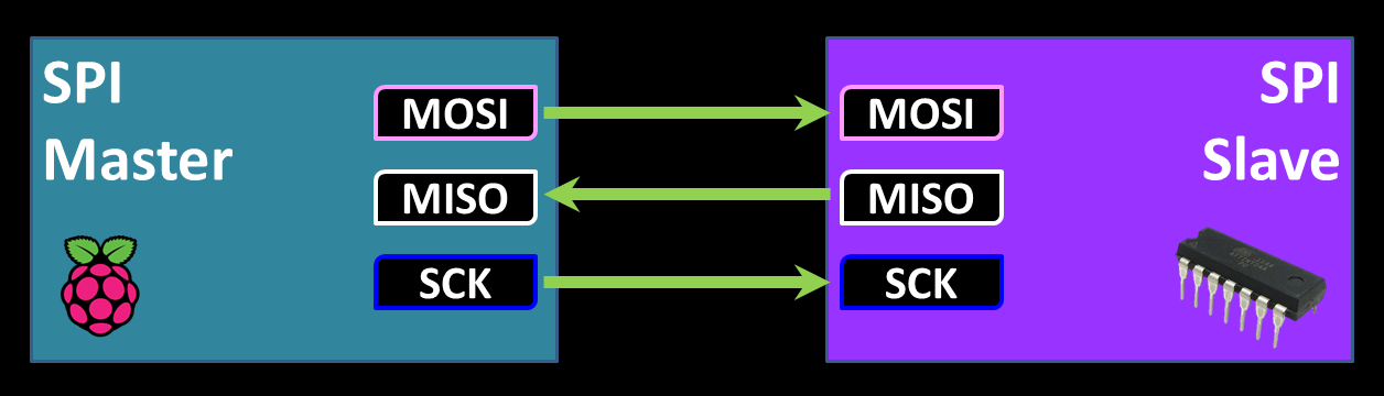
It requires 3 wires. MOSI which is the Master Output, Slave Input. It handles output from master. MISO which is the Master Input, Slave Output. It handles the output from slave. Serial clock is generated by the master and synchronizes the timing between devices. If you have more than 1 slave then a chip enable line, also called slave select is required for each additional slave. For the next example we’ll keep it simple to one slave so we won’t need the extra chip enable lines.
The Pi will be the master and the AVR will be the slave. SPI protocol allows us to transmit bytes between the 2 devices. Every time a byte is sent from the master, the slave can simultaneously return a byte. Both devices have a memory location containing a byte and the protocol basically swaps the 2 bytes. This provides bi-directional communication.
Before using SPI on the Raspberry Pi, we have to enable it with raspi-config.
sudo raspi-config
From the raspi-config menu, select Advanced Options; then SPI. Select Yes for “Would like the SPI interface to be enabled”. Hit OK a reboot is required and Yes for “the SPI kernel module to be loaded by default”. Please reboot the Pi after enabling SPI.
After rebooting, you can test that SPI is enabled using lsmod:
lsmod | grep spi
It should return spi_bcm2708 or spi_bcm2835 depending on your Pi version. You can also cat /boot/config.txt. The file should include the uncommented line: dtparam=spi=on
The python SPI library requires python2.7 dev which can be installed with apt-get install:
sudo apt-get install python2.7-dev
The python SPI library is called py-spidev. Currently the doceme fork seems to be the most up-to-date. It can be installed using git:
cd~
git clone https://github.com/doceme/py-spidev.git
cd py-spidev
sudo python setup.py install
 It is usually necessary to reset the SPI bus after you use AVRDude. The command rmmod removes the module and modprobe reloads it. If you’re troubleshooting SPI, this is a good place to start:
sudo rmmod spi_bcm2708
sudo modprobe spi_bcm2708
I wrote a short python program to allow the Pi to set the color of an RGB led connected to an ATtiny24 AVR chip. It can also read a potentiometer connected to the AVR. It will use the same hardware wiring from the previous example. It starts by importing, instantiating, opening and setting the speed of the SPI module:
import spidev
spi = spidev.SpiDev()
spi.open(0,0)
spi.max_speed_hz = 250000
Bi-directional communication is handled by the spi.xfer2 method.
resp = spi.xfer2(color)
This method allows you to pass an argument to the AVR and at the same time an argument is returned from the AVR. In this case, a color is sent to the AVR to change a connected RGB LED and a response is returned that indicates the value of a connected potentiometer.
I wrote another basic program for the AVR. Here is the main loop:
Do
   If Usi_data_ready = 1 Then
      Reset Usi_data_ready
      'Set RGB LED passed value in SPI buffer
      Portb = Usidr
      'Read ADC
      W = Getadc(0)
      'Scale ADC value to byte
      Shift W , Right , 2
      'Place ADC value in SPI buffer
      Usidr = W
   End If
   Waitms 32
Loop
It checks a flag to see if any SPI data has been transmitted. If so the flag is reset and Port B is set to the value transmitted from the Pi which can be between 1 and 7. This translates to every non-zero combination of bits on the 3 Port B pins and changes the color of the RGB LED accordingly. Next the potentiometer is polled and the voltage value is scaled to a byte (0 – 255). This value is then placed into the USI data register which is passed back to the Pi. This allows the Pi to read the state of the pot on the AVR.
The python program has the maximum SPI communication speed throttled to 250,000 Hz.
spi.max_speed_hz = 250000
You can increase this speed, but you will have to increase the MHz of the AVR. The ATtiny has a default speed of 1 MHz which saves power but is a bit slow. I found that communication errors occur if SPI is running too fast and the AVR is clocked too slow. The ATTiny speed can easily be increased to 8 MHz with a software adjustment in the basic code:
$crystal = 1000000
 change to
$crystal = 8000000
The AVR fuses also need to be programmed to increase the speed. The default low fuse setting of 62 needs to be changed to E2. This disables the clock divide by 8 function and increases the AVR speed from 1 MHz to 8 MHz. There is an excellent online AVR fuse calculator that helps you determine the proper fuse bytes. It also provides you with AVRDude parameters so you can copy and paste them. Here is the AVRDude command to modify the fuse settings:
sudo /usr/bin/avrdude -p t24 -c linuxgpio -U lfuse:w:0xe2:m
The -U lfuse:w switch writes hex value e2 to the AVR lower fuse. This increases the AVR speed to 8 MHz.
Please exercise caution when programming the fuses. If you make a mistake you can brick the AVR.
Downloads:
BascomAVR Basic RGB LED Test Code v.1.0 – Released 7/1/2015 – For ATtiny24
BascomAVR Basic SPI Test Code v.1.0 – Released 7/1/2015 – For ATtiny24
Python SPI Test Code v.1.0 – Released 7/1/2015 – For ATtiny24