
This tutorial demonstrates how to set up and program an ESP32 device running MicroPython from a Raspberry Pi.
The ESP32 is a very inexpensive versatile chip designed for efficient Wi-Fi and Bluetooth including BLE. It has a powerful 240MHz dual core microcontroller with 520K of SRAM. It is designed for mobile devices so it has ultra-low power consumption. The ESP32 chip has 32 GPIO pins with support for I2C, I2S, SPI and UART. In addition it has multiple analog to digital channels and digital to analog, hardware accelerated encryption, pulse width modulation, capacitance touch interfaces and a lot more.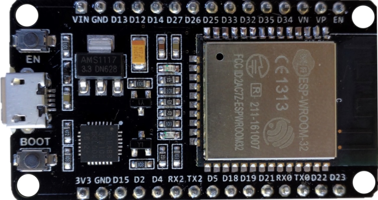
The ESP32 is a more powerful successor to the very popular ESP8266. The following chart compares the specs.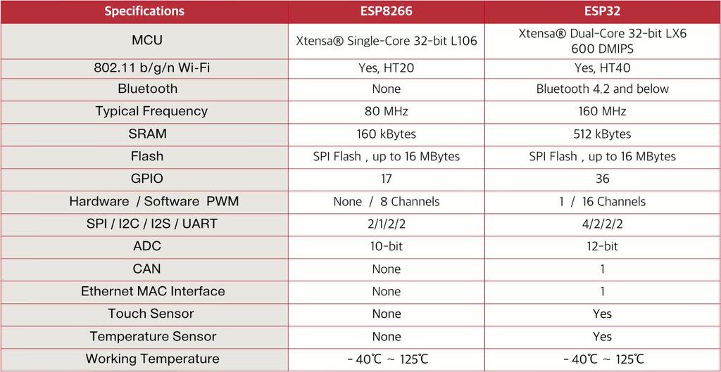
One of the main reasons I like the ESP32 and the ESP8266 is that you can program them in Python. More specifically, MicroPython, which is a very efficient streamlined version of the Python 3 programming language that is optimized to run on microcontrollers, such as the ESP32.
The Raspberry Pi is great for many projects, but it is a full-fledged computer with a Linux operating system. For simple repetitive task such as monitoring sensors and controlling relays it’s often easier, cheaper, more reliable and more efficient to use a microcontroller such as an Arduino which boots up instantly and just runs your program. Arduinos such as the Uno are usually programmed using a set of the C language using the Arduino IDE, which can also be used to program the ESP32. Instead of C, this tutorial focuses on MicroPython, which works great when integrating with a Raspberry Pi because you can use Python on both devices for all the code.
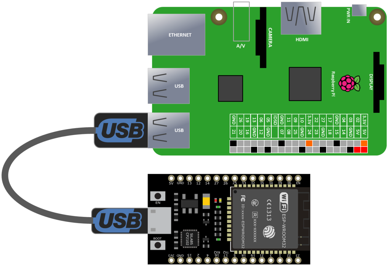
To get started the MicroPython firmware needs to be uploaded to the ESP32. This can be done with a simple micro-USB cable which provides a 2 way serial interface between the Pi and the ESP32. It also provides 5 volts to power the ESP32.
Before uploading the firmware, please make sure the Pi is up-to-date. From a terminal, type the following:
sudo apt-get update && sudo apt-get upgrade
I recommend you use the latest version of Raspbian to ensure you have all the necessary software.
A utility called ESPTool is used to upload the MicroPython firmware to the ESP32. It is installed using pip3 to target Python3:
sudo pip3 install esptool
Next the USB port needs to be determined using dmesg | grep ttyUSB. The results should show a CP210x UART to USB bridge attached to a USB port. Below the port is ttyUSB0.
dmesg | grep ttyUSB
[   11.263101] usb 1-1.4: cp210x converter now attached to ttyUSB0
Some boards need to be put in programming mode using the push buttons on the board (or grounding GPIO 0 and 2 during boot) before you can use the ESPtool. However, I’ve found that it’s not necessary on the ESP32 (at least not on mine.) The ESPTool flash_id command can be used to ensure everything is working. Specify the port with double dash port followed by /dev/ and the port name returned by the dmesg command above.
esptool.py --port /dev/ttyUSB0 flash_id
esptool.py v2.0.1
Connecting........_
Detecting chip type... ESP32
Chip is ESP32D0WDQ6 (revision 0)
Uploading stub...
Running stub...
Stub running...
Manufacturer: c8
Device: 4016
Detected flash size: 4MB
Hard resetting...
The query returns basic info such as the chip type (ESP32) and flash size (4 MB). Before uploading the firmware it is recommended to erase the ESP32, which can also be done with the ESPTool:
esptool.py --port /dev/ttyUSB0 erase_flash
A copy of the MicroPython firmware is required. You could build it yourself from the source code on the MicroPython GitHub ESP32 repo, but is much easier to just download a ready-to-go daily build.
Once the firmware is downloaded it can be uploaded with the ESPTool using the write_flash command. The hex value indicates the starting memory address and it is followed by the path to the downloaded MicroPython ESP32 firmware file.
 UPDATE: the starting address now needs to be 0x1000 instead of zero.
esptool.py --port /dev/ttyUSB0 write_flash 0x1000 <path to firmware file>
MicroPython boards have a Read-Eval-Print Loop (REPL) which is a simple interactive programming environment. It’s similar to the Python Idle shell. On the ESP32, the REPL is accessed using a serial connection. Other boards like the ESP8266, which is the predecessor to the ESP32, also have a Web REPL which allows you to manage and program them over the web. Currently, this feature has not yet been implemented on the ESP32 along with many other features, but new stuff is being added daily so there might be more options in the future. The ESP32 now supports Web REPL, but you can only transfer 1 file at a time (no folders), the security is very weak and it’s buggy. For now we’ll stick to serial. The same USB cable that was used to upload the ESP32 firmware can also be used to access the REPL. Any serial program such as PuTTY or Screen should work with the REPL. However, these programs won’t let you manage the ESP32 file system which can be used to store your programs. Actually you can access some file commands by writing Python code, but this is cumbersome and still does not provide for file transfers between the ESP32 and the Pi. Ideally you want a program that provides a REPL terminal and also can perform file management. I’ve tried several programs and currently my favorite is rshell. It can be installed using pip:
sudo pip3 install rshell
This simple program will run on the Raspberry Pi and allow you to access the REPL terminal on the ESP32. It also provides file management to transfer and manipulate files on both the Pi and the ESP32. To start rshell, type rshell and specify 30 for the buffer size and your USB port:
rshell --buffer-size=30 -p /dev/ttyUSB0
The first prompt can be used to execute file commands. For example, type boards to get a list of connected boards. The first line returned should start with the board ID which for my ESP32 is pyboard.
/home/pi> boards
pyboard @ /dev/ttyUSB0 connected Dirs: /boot.py
The boot.py file is automatically run at startup and contains code to set up the board and finish booting. You typically don’t want to edit it. However, you can add a file called main.py if you need your own code to run at start up after the boot.py.
Type repl to open the MicroPython programing environment. The terminal will now accept Python code. For example, print hello world, outputs hello world.
/home/pi> repl
Entering REPL. Use Control-X to exit.
>
MicroPython v1.9.1-218-g56f05137 on 2017-07-01; ESP32 module with ESP32
Type "help()" for more information.
>>>
>>> print('Hello World')
Hello World
>>>
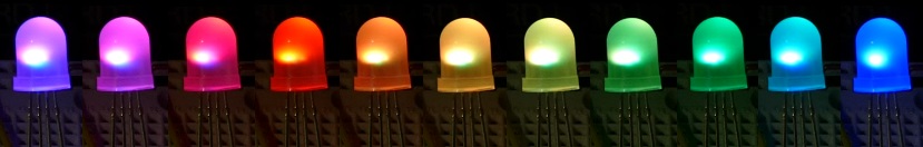
Next, let’s upload a MicroPython program to control a NeoPixel LED on the ESP32. A NeoPixel is an RGB led with a built in chip (usually WS2812B or SK6812) to control color and brightness. It can be controlled using a single data line. They are often sold in strips with multiple LED’s, but for this demo a single 8mm LED is used. These single 8mm LED’s can also be daisy-chained using a single data line.
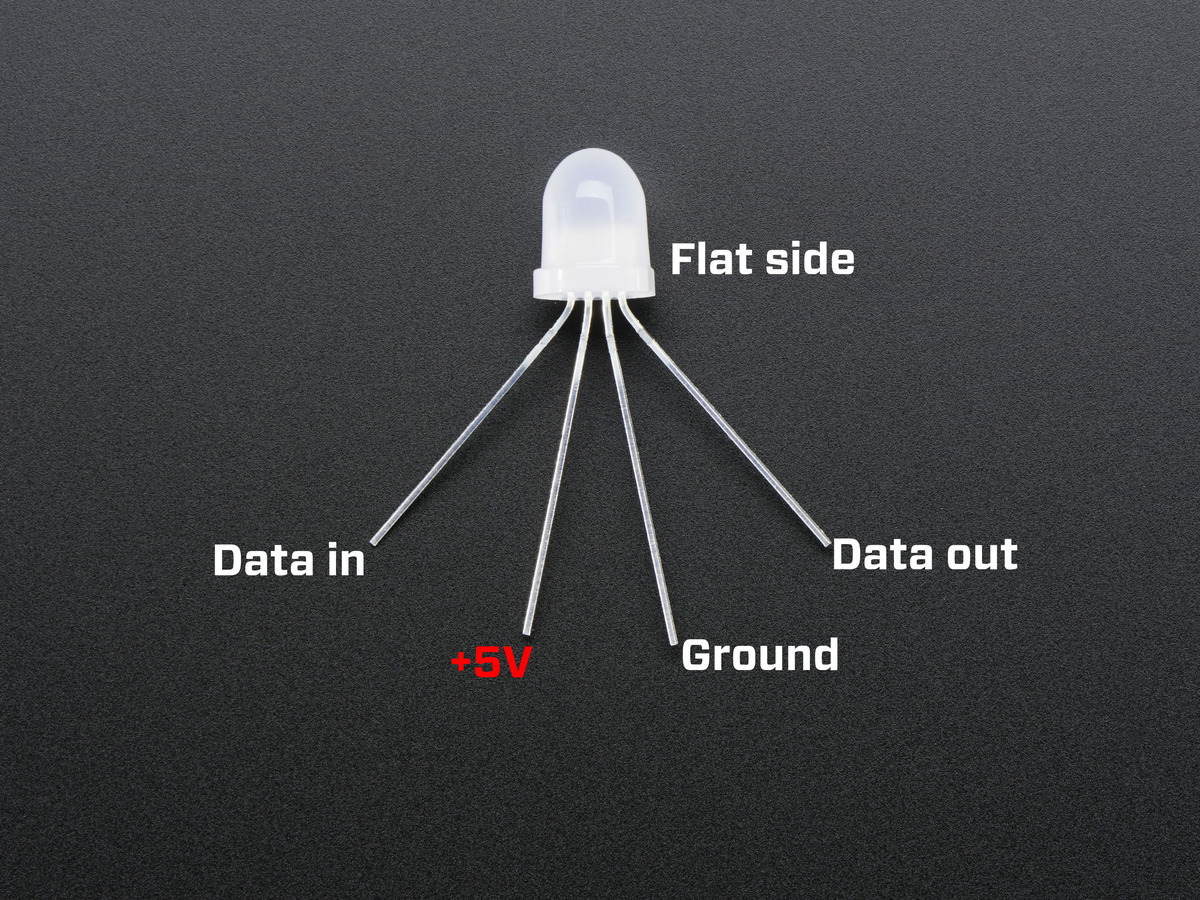
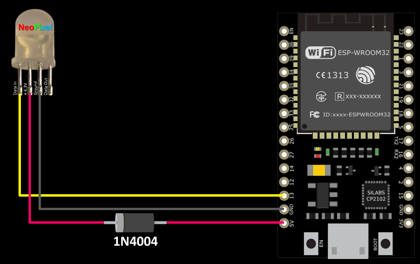
It is very easy to connect a NeoPixel to the ESP32. A 5 V pin provides power. A 1N4004 diode is used to drop the voltage from 5 V to 4.3 V which allows the NeoPixel to read the ESP32’s 3.3 V output. The ESP32 3.3 V data output needs to be at least 70% of the NeoPixel’s supply voltage. At 5 V it’s outside this range at 66% but at 4.3 V it’s good to go at 76%. A ground from the ESP32 is connected to the ground on the NeoPixel. GPIO 13 is connected to the data in. Please note that a single NeoPixel can use up to 60mA at full brightness. Therefore, if you want to run a strip of LED’s, please use an external power source to avoid damaging the board and it would be preferable to use a level shifter on the data line instead of the diode approach.
Here’s the MicroPython code to control the NeoPixel. The Pin library is very similar to the Raspberry Pi GPIO library. It lets you reference and control the ESP32 GPIO pins. The NeoPixel library drives NeoPixel LED’s and strips.
Since MicroPython is a subset of Python, it doesn’t have all the standard libraries. For example, an easy way to cycle RGB LED colors is to vary the hue between 0 and 1. This can be done with the hsv_to_rgb method which is part of the Python colorsys library. It’s not included with MicroPython, but I can just add the function I need to the code. HSV is a common cylindrical-coordinate representation of points in an RGB color model. The hsv_to_rgb function simply converts an HSV value (hue, saturation and brightness) to an RGB value (red, green, blue).
"""NeoPixel LED Demo."""
from machine import Pin
from neopixel import NeoPixel
from time import sleep


def hsv_to_rgb(h, s, v):
    """
    Convert HSV to RGB (based on colorsys.py).

        Args:
            h (float): Hue 0 to 1.
            s (float): Saturation 0 to 1.
            v (float): Value 0 to 1 (Brightness).
    """
    if s == 0.0:
        return v, v, v
    i = int(h * 6.0)
    f = (h * 6.0) - i
    p = v * (1.0 - s)
    q = v * (1.0 - s * f)
    t = v * (1.0 - s * (1.0 - f))
    i = i % 6

    v = int(v * 255)
    t = int(t * 255)
    p = int(p * 255)
    q = int(q * 255)

    if i == 0:
        return v, t, p
    if i == 1:
        return q, v, p
    if i == 2:
        return p, v, t
    if i == 3:
        return p, q, v
    if i == 4:
        return t, p, v
    if i == 5:
        return v, p, q


np = NeoPixel(Pin(13), 1)
spectrum = list(range(2048)) + list(reversed(range(2048)))


try:
    while True:
        for c in spectrum:
            hue = c / 2048.0
            np[0] = hsv_to_rgb(hue, 1, .15)
            np.write()
            sleep(.01)

except KeyboardInterrupt:
    print ("\nCtrl-C pressed.  Cleaning up and exiting...")
finally:
    np[0] = (0, 0, 0)  # Turn off NeoPixel
    np.write()
A NeoPixel is instantiated, on GPIO pin 13. One indicates the number of LED’s. Spectrum is a list to represent 2048 colors. The first range is zero to 2047 and the 2nd is 2047 to zero. A try statement to catch errors wraps the main while loop which is infinite. A for loop cycles through the color spectrum range (0 to 2047 and back to 0). Hue is set to a value from 0 to 1 (divided into 2048 steps.) NP[0] refers to the first NeoPixel LED. In this case, there is only one. If we were using a strip we could reference other LED’s using other numbers. The hsv_to_rgb function is passed the hue, 1 for saturation and brightness is set to 15%. The np.write method sets the NeoPixel LED to the previously specified color. The loop sleeps for ten milliseconds and continues. Except is used to gracefully exit the program on ctrl-C. Finally ensures the LED is turned off on exit by setting red, green and blue to zeros.
Back in rshell type ctrl-X if you are still in the REPL to exit back to the main rshell terminal. Navigate to the folder where the program is saved. You can use cd and ls just like in a regular terminal. Then use cp to copy the program file to the ESP32 which is specified with /pyboard:
/home/pi/Documents> cp rgb.py /pyboard
Type repl to return the REPL and type import rgb to run the rgb.py program.
/home/pi> repl
Entering REPL. Use Control-X to exit.
>
MicroPython v1.9.1-218-g56f05137 on 2017-07-01; ESP32 module with ESP32
Type "help()" for more information.
>>>
>>> import rgb
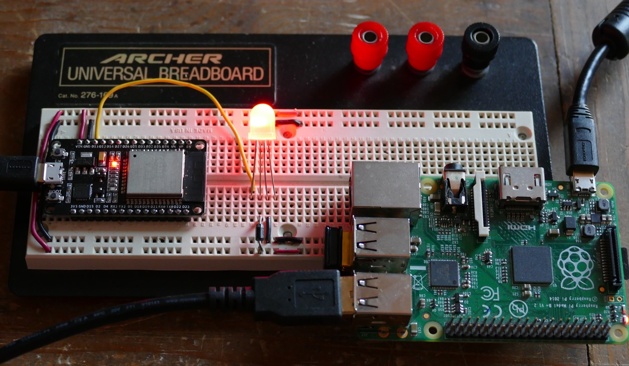
Here’s a pic of the breadboard with an ESP32 and a NeoPixel.
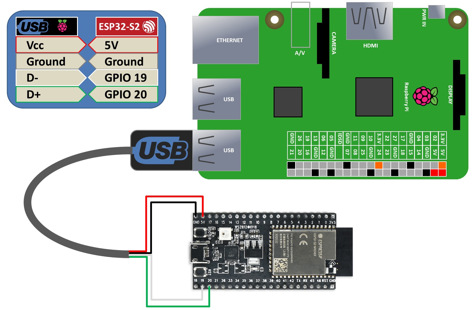
 UPDATE: ESP32-S2 set up is slightly different:
For the ESP32-S2, first put the board in boot mode by holding down the boot button and then toggling the RST (reset) button. Then release the boot button. Next confirm you have the latest version of ESPTool:
sudo pip3 install --upgrade esptool
The rest of the MicroPython firmware installation is the same as above. Programming the S2 also uses the ESP32-S2’s UART which is usually connected to the micro-USB jack on most S2 boards. However, because of the new USB functionality available on the S2, I think you have to use the native USB (DFU) for rshell access. This usually requires a USB breakout cable which you can make by cutting one end off of a USB cable. The USB cable is then connected as follows:
Test the USB (DFU) connection by using dmesg and you should see ttyACM0.
pi@raspberrypi:~ $ dmesg | grep ttyACM
[  770.355362] cdc_acm 1-1.5:1.0: ttyACM0: USB ACM device
Rshell can then be used on the ttyACM0 port.
pi@raspberrypi:~ $ rshell  -p /dev/ttyACM0
Using buffer-size of 32
Connecting to /dev/ttyACM0 (buffer-size 32)...
Trying to connect to REPL  connected
Retrieving sysname ... esp32
Testing if ubinascii.unhexlify exists ... Y
Retrieving root directories ... /boot.py/
Setting time ... Mar 01, 2022 13:12:02
Evaluating board_name ... pyboard
Retrieving time epoch ... Jan 01, 2000
Welcome to rshell. Use Control-D (or the exit command) to exit rshell.
/home/pi> repl
Entering REPL. Use Control-X to exit.
>
MicroPython v1.18 on 2022-01-17; ESP32-S2-WROVER with ESP32-S2
Type "help()" for more information.
>>>
Part 2 of this tutorial demonstrates MQTT protocol.
Resources:
Adafruit NeoPixel UberGuide
Sipping Power with NeoPixels
MicroPython Forum a very helpful community to answer MicroPython related questions.
MicroPython-lib a great source for additional MicroPython libraries.
NeoPixel RGB LED Python Code from Video – Released 7/16/2017