
This tutorial demonstrates how to flash CircuitPython onto an inexpensive nRF52840 dongle using OpenOCD and a Raspberry Pi. The Bluefruit LE Connect app will also be used to control the dongle from a mobile phone using BLE.
This is my 2nd CircuitPython tutorial. The first one demonstrated getting started with the Adafruit Feather nRF52840 Express which is very easy because it comes preloaded with a CircuitPython compatible bootloader.
For this tutorial, I’ll be using the nRF52840 dongle from Nordic Semiconductor. The part number is PCA10059.
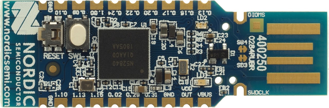
The dongle is very inexpensive and stocked by most of the large online electronics distributers. It’s similar to the Adafruit Feather except it doesn’t have a battery connector or charging circuit. The board is designed by Nordic to help develop wireless solutions such as Bluetooth Low Energy.
The main chip is an nRF52840 SoC. The board has a card edge USB connector so it can be plugged directly into a computer without a cable. There are 20 castellated mounting holes which can be used to solder directly to another board or accept common 2.54 mm pin headers. They expose 15 GPIO pins. There is a user switch (SW1), a reset button, an RGB LED (LD2) and a regular green LED (LD1).
On the bottom side of the board is an unpopulated 10 pin solder pad (P1). It is for a standard 1.27 mm pitch Serial Wire Debug interface (SWD) which can be used for debugging or programming. The SWD interface also exposes a plug of nails adapter for use with a spring-pin connector.
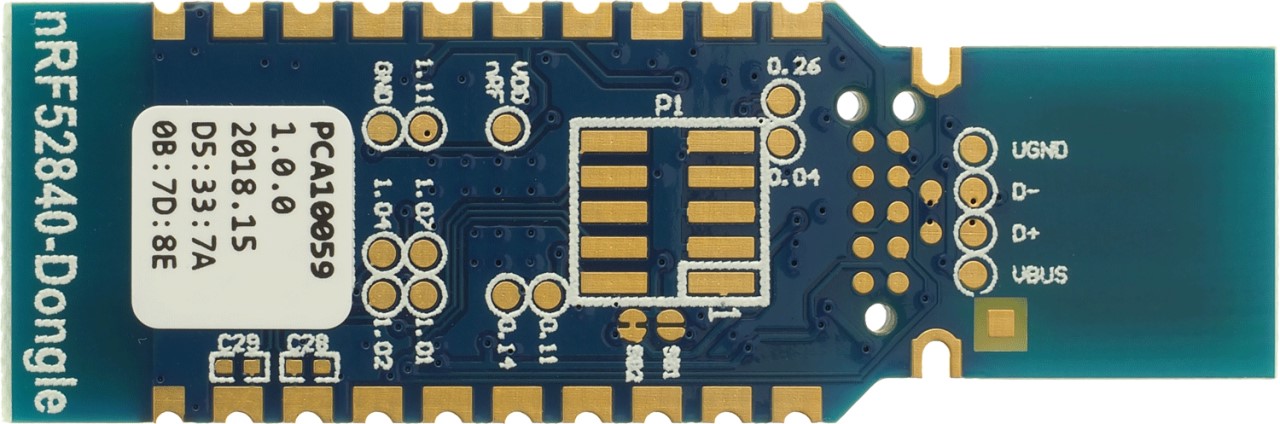
The bottom center of the board contains solder pads for an additional 9 GPIO’s. There are also 2 more castellated mounting holes inset from the others that provide easy access to the SWD clock (SWDCLK) and bi-directional data input/output (SWDIO). This is convenient because the dongle’s bootloader is not compatible with CircuitPython. Nordic provides utilities for DFU programming over USB, but they won’t let you overwrite the bootloader unless it’s vendor signed. As far as I can tell the dongle’s existing bootloader can only be overwritten using an SWD compatible debugging probe such as Segger J-link.
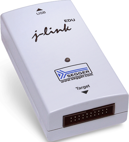
I like the J-Link because it just works. It’s supported by most IDEs and compatible with most MCUs. It’s very popular and well documented. I’ve used it many times to recover bricked boards. A convenient way to connect the J-link to the nRF52840 dongle is with a Tag-Connect 2050 plug-of-nails connector.
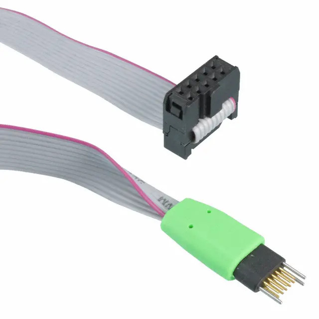
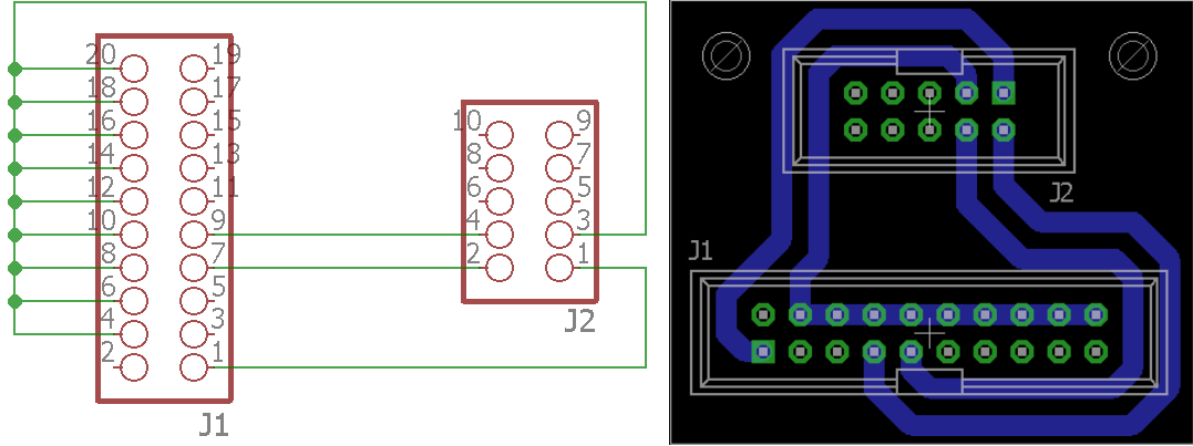
It mates well with the nRF52840 dongle. The 3 outer pins slide through the board while the spring pins make contact with the SWD interface. You can physically hold it in place during programming or use a retaining clip sold separately to secure it. My Tag-Connect 2050 came with a 10 pin plug so I etched a small adapter board. Here are the eagle files.
The J-link is a great tool for debugging and programming. Unfortunately it’s expensive. Therefore, I’ve come up with an alternative low cost solution for this tutorial.
OpenOCD which is short for Open On-Chip Debugger, is an open source project designed to provide debugging, in-system programming and boundary-scan testing for embedded target devices. It has support for the nRF52 chips and it supports using the Raspberry Pi’s GPIO as a debug adapter.
Currently OpenOCD requires manual installation to get the necessary features. I recommend you use a freshly wiped Raspberry Pi 3 running the latest updated version of Raspbian. A few necessary libraries including autoconf, libtool and libusb-dev will be required. These prerequisites may vary if you’re using a different OS. Install the libraries using apt-get install.
sudo apt-get install autoconf libtool libusb-dev
CD into the home directory and use git clone to download the OpenOCD repository into a folder called openocd-code. The recursive parameter is used to pull any necessary submodules. Afterwards, CD into the new folder.
cd ~
git clone --recursive git://git.code.sf.net/p/openocd/code openocd-code
cd openocd-code
Run the bootstrap script to begin the configuration.
./bootstrap
Next run the configure script. The –enable-BCM2835GPIO parameter is passed to enable Raspberry Pi GPIO support. This allows the Pi’s GPIO pins to be used as a bit bang debugger. Afterwards a configuration summary is displayed. Don’t worry if it doesn’t mention the Raspberry GPIO. It still works.
./configure --enable-bcm2835gpio
The make utility is used to compile the source code. It takes around 20 minutes to complete on a Pi3 and will probably take a lot longer on an older Pi.
make
Sudo make install is used to install OpenOCD.
sudo make install
When OpenOCD is run, it looks for a config file to set the interface and target. The interface is the hardware debug adapter which will be the Raspberry Pi GPIO. The target device is the nRF52840 chip. Create a new folder in the home directory called openocd-config and use Nano to create a blank openocd.cfg file.
cd ~
mkdir openocd-config
cd openocd-config
nano openocd.cfg
Here’s the contents of the openocd.cfg file. Uncomment lines appropriate to your Raspberry Pi. If you encounter errors, try uncommenting adapter_khz and set it to a lower speed.
interface bcm2835gpio

# Raspi1 peripheral_base address
# bcm2835gpio_peripheral_base 0x20000000
# Raspi2 and Raspi3 peripheral_base address
bcm2835gpio_peripheral_base 0x3F000000


# Raspi1 BCM2835: (700Mhz)
# bcm2835gpio_speed_coeffs 113714 28
# Raspi2 BCM2836 (900Mhz):
# bcm2835gpio_speed_coeffs 146203 36
# Raspi3 BCM2837 (1200Mhz):
bcm2835gpio_speed_coeffs 194938 48
# Raspi3 A/B+ BCM2837 (1400 MHz)
# bcm2835gpio_speed_coeffs 227428 56
# Raspi4 BCM2711 (1500Mhz):
# bcm2835gpio_speed_coeffs 243704 60

# SWD GPIO set: swclk swdio
bcm2835gpio_swd_nums 25 24

transport select swd

set CHIPNAME nrf52840
source [find target/nrf52.cfg]

# Uncomment & lower speed to address errors
# adapter_khz 1000

init
targets
reset halt
I relied heavily on a post to the Linux Device Hacking forum by Joerg999 to derive the settings for the openocd.cfg file. The SWD GPIO pins are specified for the clock and the data input output as GPIO 25 and 24 respectively. The transport is set to SWD as opposed to JTAG. Chipname is set to the nRF52840. OpenOCD comes with a configuration file for the nRF52 chips so source can be used to specify the target. Init to initialize. Targets, should display the single target status for the nRF52840. Reset halt, halts the target.
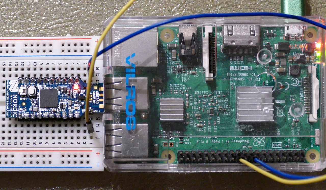
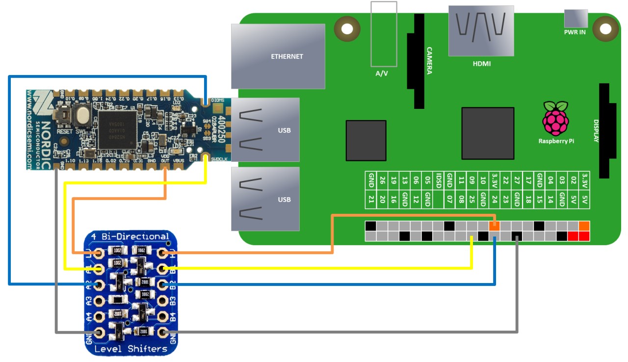
Before using OpenOCD the SWD wiring needs to be set up between the Pi and the nRF52840 dongle. The SWDIO pin on the dongle is connected to GPIO 24. The SWDCLK pin is connected to GPIO 25. Power and ground are connected by plugging the dongle into the Pi. The nRF52840 has an on-chip regulator that can be set from 1.8 to 3.3 V. My board came set to 3.3 V so its GPIO’s are Pi friendly.
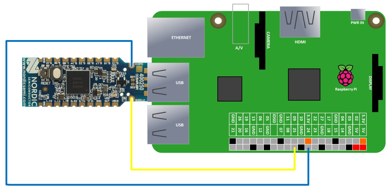
I recommend you disconnect power to the Pi before making any connections.
Make sure you are in the openocd-cfg folder and type sudo openocd to start the program. The summary should look as follows. If you get errors check your wiring and try lowering the clock speed.
pi@raspberrypi:~/openocd-config $ sudo openocd
Open On-Chip Debugger 0.10.0+dev-00689-g6c2020eb (2019-02-11-21:41
Licensed under GNU GPL v2
For bug reports, read
	http://openocd.org/doc/doxygen/bugs.html
BCM2835 GPIO nums: swclk = 25, swdio = 24
adapter speed: 1000 kHz
cortex_m reset_config sysresetreq
Info : BCM2835 GPIO JTAG/SWD bitbang driver
Info : SWD only mode enabled (specify tck, tms, tdi and tdo gpios to add JTAG mode)
Info : clock speed 1004 kHz
Info : SWD DPIDR 0x2ba01477
Info : nrf52840.cpu: hardware has 6 breakpoints, 4 watchpoints
Info : nrf52840.cpu: external reset detected
Info : Listening on port 3333 for gdb connections
    TargetName         Type       Endian TapName            State
--  ------------------ ---------- ------ ------------------ ------------
 0* nrf52840.cpu       cortex_m   little nrf52840.cpu       running
target halted due to debug-request, current mode: Thread
xPSR: 0x01000000 pc: 0x00000a80 msp: 0x20000400
Info : Listening on port 6666 for tcl connections
Info : Listening on port 4444 for telnet connections
The summary should indicate OpenOCD is listening for telnet connections on port 4444. Next install a telnet client such as the following:
sudo apt-get install telnet
Telnet into OpenOCD using localhost on port 4444.
telnet localhost 4444
Adafruit’s GitHub site contains an nRF52 bootloader repo that’s compatible with the PCA10059 dongle and CircuitPython. Click releases and scroll down to the PCA10059 bootloader and download the most recent hex file. Once the hex file is downloaded, the nRF52840 dongle can be erased and the hex flashed.
 WARNING: wiping the chip will reset the voltage regulator.
When you erase the chip, it clears the User Information Configuration Registers (UICR). This includes the RegOut0 register which controls the chip’s voltage regulator output. This was set to 3.3 V at the factory, but when it’s cleared, the default value is 1.8 V which is too low to be compatible with the Pi’s 3.3 V GPIO pins. Fortunately the settings don’t take effect until the chip is reset and when the Adafruit bootloader is flashed it will set the regulator back to 3.3 V. However, if the dongle is reset , unplugged or something goes wrong before flashing then the chip will basically be bricked and there would only be 2 recovery options.
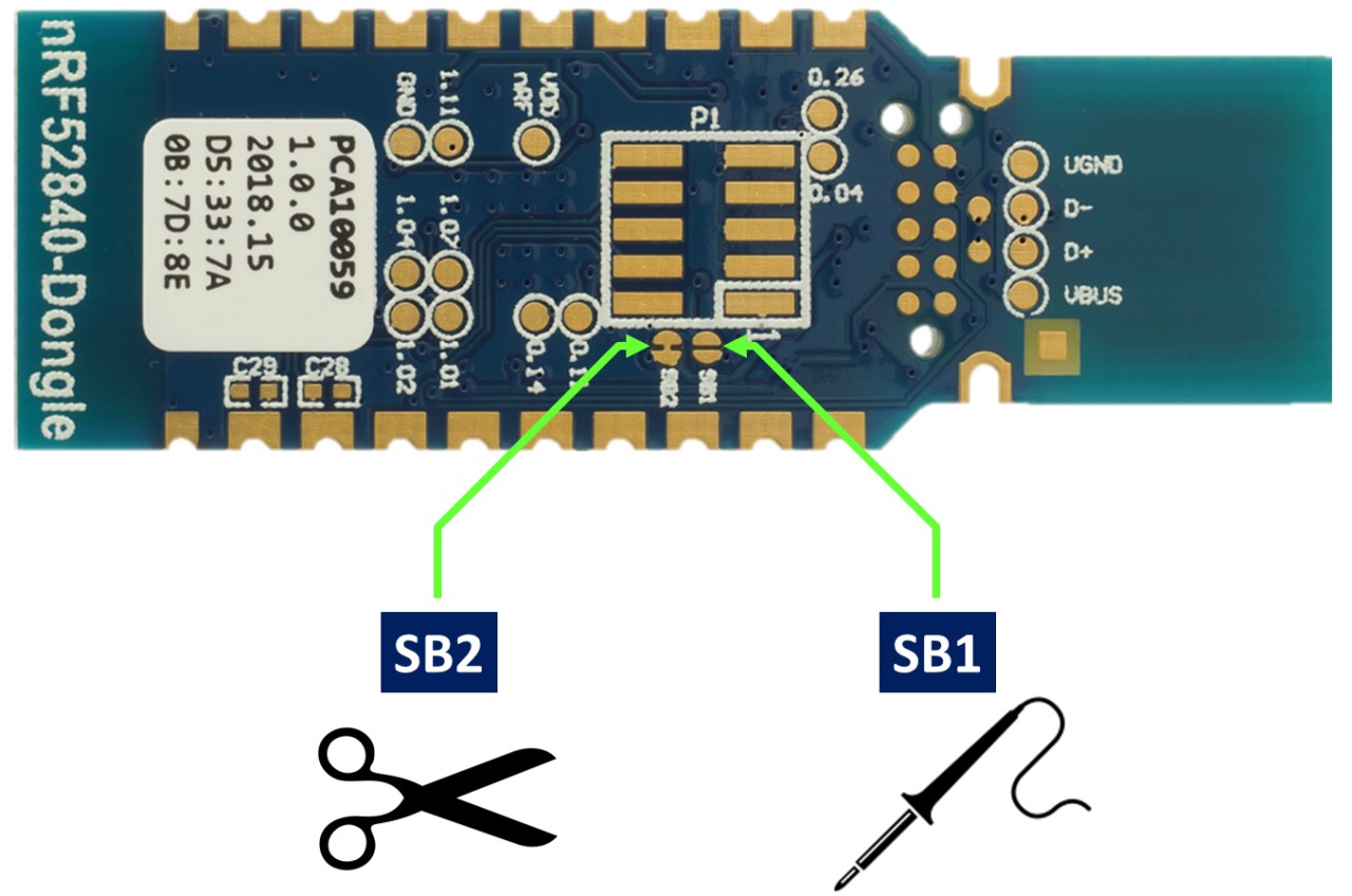
You can modify the dongle to use an external 3.3 V power supply through the VDDOUT pin. This is accomplished by cutting the SB2 trace on the bottom of the board and soldering together SB1. .
Alternatively, you could use a debugger that supports level shifting such as the J-link EDU which has a target voltage range of 1.2 to 5 V. The J-link Mini won’t work because its minimum target voltage is 3.3 V. Another option is to use a level shifter board between the Pi and the nRF52840 dongle such as this 4 channel Adafruit board.
The following Open OCD commands will erase the chip, flash the new firmware and verify. Please make sure you specify the full path of the hex file. For example: /home/pi/Downloads/pca10059_bootloader-123.hex
nrf5 mass_erase
flash write_image <Full path of hex file>
verify_image <Full path of hex file>
If there are no errors then it should be safe to reset the chip.
reset run
Afterwards, a new device folder called NRF52BOOT should be detected by the Pi.
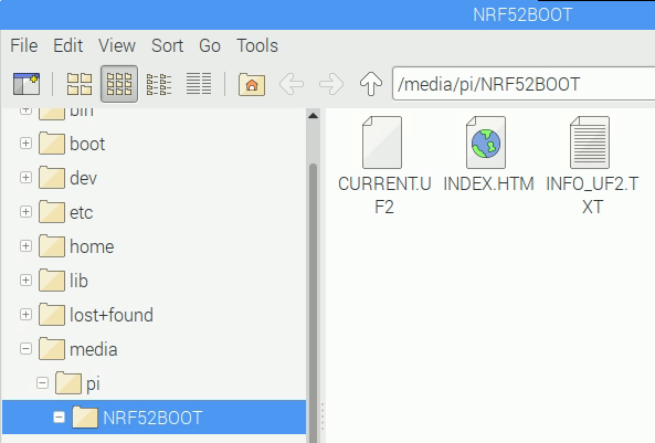
To install CircuitPython, just download the most recent UF2 file for the PCA10059 from the CircuitPython repo and copy it to the NRF52BOOT folder.
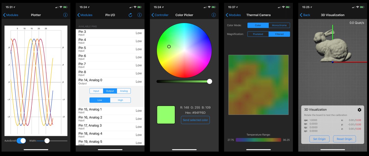
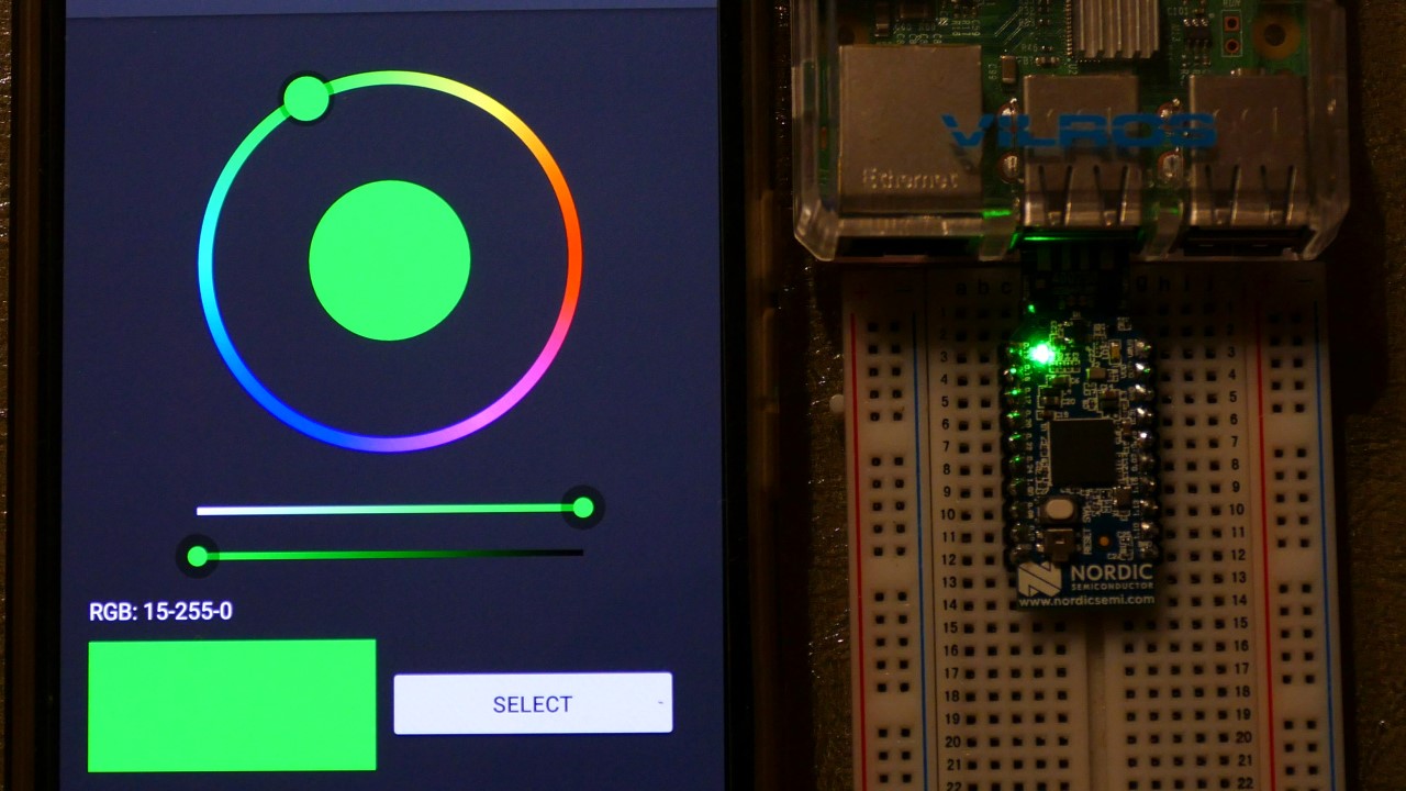
The demo program in this tutorial will use the free Adafruit Bluefruit LE Connect app which has versions for both Android and iOS devices. The app provides a variety of tools to communicate with BLE devices. The demo will use the color picker feature to control the dongle’s RGB LED.
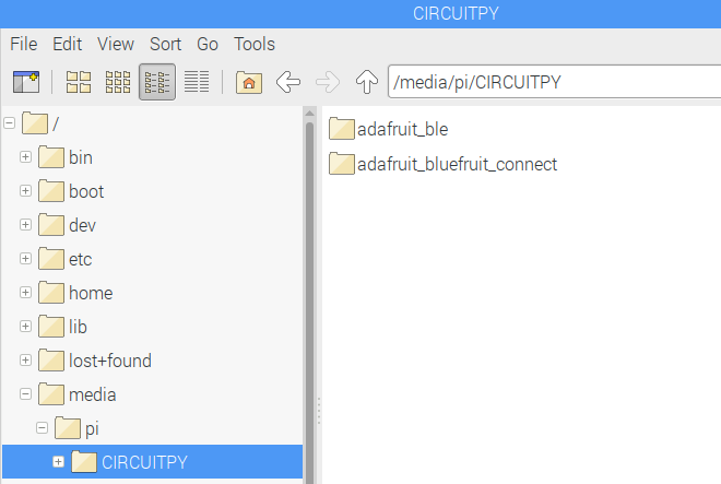
Two libraries from the Adafruit CircuitPython Bundle will be required to communicate with the Bluefruit LE Connect app:
- adafruit_ble
- adafruit_bluefruit_connect
Download the latest bundle and extract the two folders to the /media/pi/CIRCUITPY device folder.
 UPDATE: Adafruit has made extensive changes to the CircuitPython BLE library. I have revised the code below appropriately.
import board
from pwmio import PWMOut
from adafruit_ble import BLERadio
from adafruit_ble.advertising.standard import ProvideServicesAdvertisement
from adafruit_ble.services.nordic import UARTService
from adafruit_bluefruit_connect.packet import Packet
from adafruit_bluefruit_connect.color_packet import ColorPacket

ble = BLERadio()
uart_server = UARTService()
advertisement = ProvideServicesAdvertisement(uart_server)

r = PWMOut(board.LED2_R, duty_cycle=0)
g = PWMOut(board.LED2_G, duty_cycle=0)
b = PWMOut(board.LED2_B, duty_cycle=0)

while True:
    ble.start_advertising(advertisement)  # Advertise when not connected.
    while not ble.connected:
        pass

    while ble.connected:
        packet = Packet.from_stream(uart_server)
        if isinstance(packet, ColorPacket):
            print(packet.color)
            dc = [-257*c+65535 for c in packet.color]
            r.duty_cycle, g.duty_cycle, b.duty_cycle = dc
The code sets up pulse width modulation (PWM) for the GPIO pins of the board’s RGB LED. A BLE UART server is set up to start advertising. The program waits for a connection. Then while connected it monitors the UART server packet stream for color packets. Upon receipt, the RGB color values (0 to 255) are scaled to the duty cycle range (0 to 65535). The values are also inverted because the onboard RGB LED sinks the cathodes. Therefore a zero pulse is full on and a 65535 pulse is off. Finally the PWM duty cycle values are updated which sets the RGB to the specified color packet.
The Bluefruit LE Connect app color picker can now be used to control the nRF52840 dongle’s RGB LED.
In case you want to restore the nRF52840 to its factory bootloader:
PCA10059 original bootloader v.1.0.1
My next tutorial demonstrates how to use CircuitPython with LCD displays and introduces the DisplayIO library.