
This tutorial will be a quick introduction to CircuitPython. A Raspberry Pi will be used to set up a Nordic nRF52840 board, run the Mu IDE and create some sample code including BLE. Adafruit Blinka will also be used to demonstrate Python compatibility between a Raspberry Pi and a microcontroller.
I have 6 previous MicroPython tutorials with videos:
- Part 1 demonstrates loading the ESP32 firmware, file manipulation with Rshell and NeoPixel LED’s.
- Part 2 uses MQTT to wirelessly transmit data from temperature/humidity sensors.
- Part 3 sets up a web server on the ESP32 that provides lighting control and sensor feedback.
- Part 4 demonstrates how to connect a color OLED display in addition to ADC and FTP.
- Part 5 demos the ESP32’s built-in capacitive touch sensors.
- Part 6 demos hosting a Web-Socket server on an ESP32 using the LoBo MicroPython build.
My previous videos focused on the ESP32. One of the most popular requests I’ve received has been to do a project with Bluetooth Low Energy or BLE. The ESP32 supports BLE but unfortunately, as of this tutorial, MicroPython does not support BLE on the ESP32. This will probably change in the future. Meanwhile I’ve been very interested in the nRF52840 chip by Nordic Semiconductor. They specialize in low power wireless technology. The chip boasts many impressive features including:
- ARM Cortex M4F 64MHz
- SPI, I²C, I2S, PWM, PMD, UART, 12 bit ADC
- 12 Mbs Native USB Controller
- NFC
- Bluetooth5 with BLE
MicroPython v1.10 added limited support for nRF52 boards but the set up process is a bit complicated, typically requiring a toolchain, code compiling and a hardware debugger to program such as a Segger J-Link. However, Adafruit recently released CircuitPython beta 4 which supports the NRF52840 and is very easy to use.
This is my first foray into CircuitPython but I have been watching the development and I’ve been very impressed by the progress and the high caliber of the programmers contributing. Therefore when Adafruit announced their new Feather nRF52840 Express board I signed up for the waiting list and got one of the first batch.
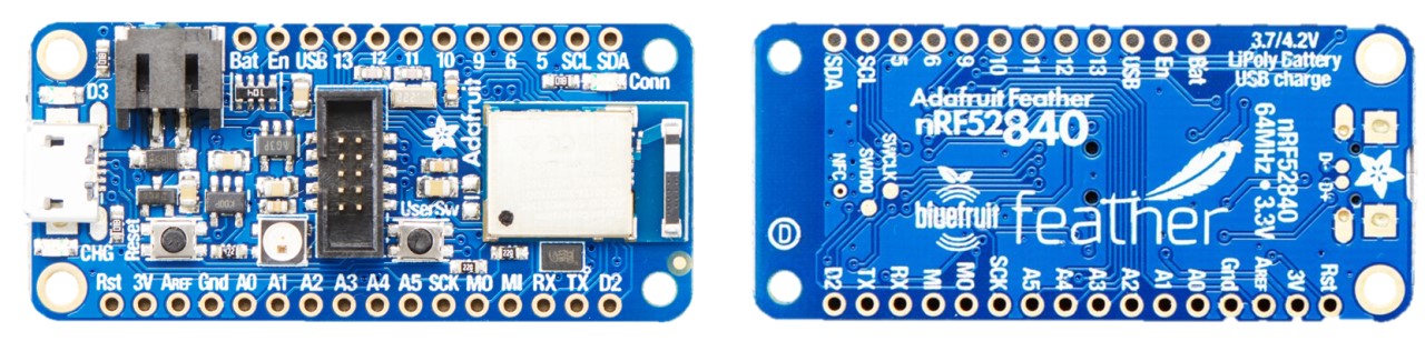
The Feather board includes:
- 21 GPIO, 6 ADC, 12 PWM (clearly labelled & breadboard friendly)
- 1 MB of Flash & 256 KB of SRAM
- 2 MB of QSPI Flash for files
- Compatible with all FeatherWings
- FCC / IC / TELEC certified module
- Raytac BT5 stack module based on Nordic nRF52840 w/ antenna
- LIPO battery jack with built in charging.
- Standard header for SWD programming & debugging
- RGB NeoPixel, red LED and user switch
The board doesn’t come with MicroPython installed, but it does come with a USB bootloader which makes installation very easy. Connect the board with a micro USB cable to the Raspberry Pi.
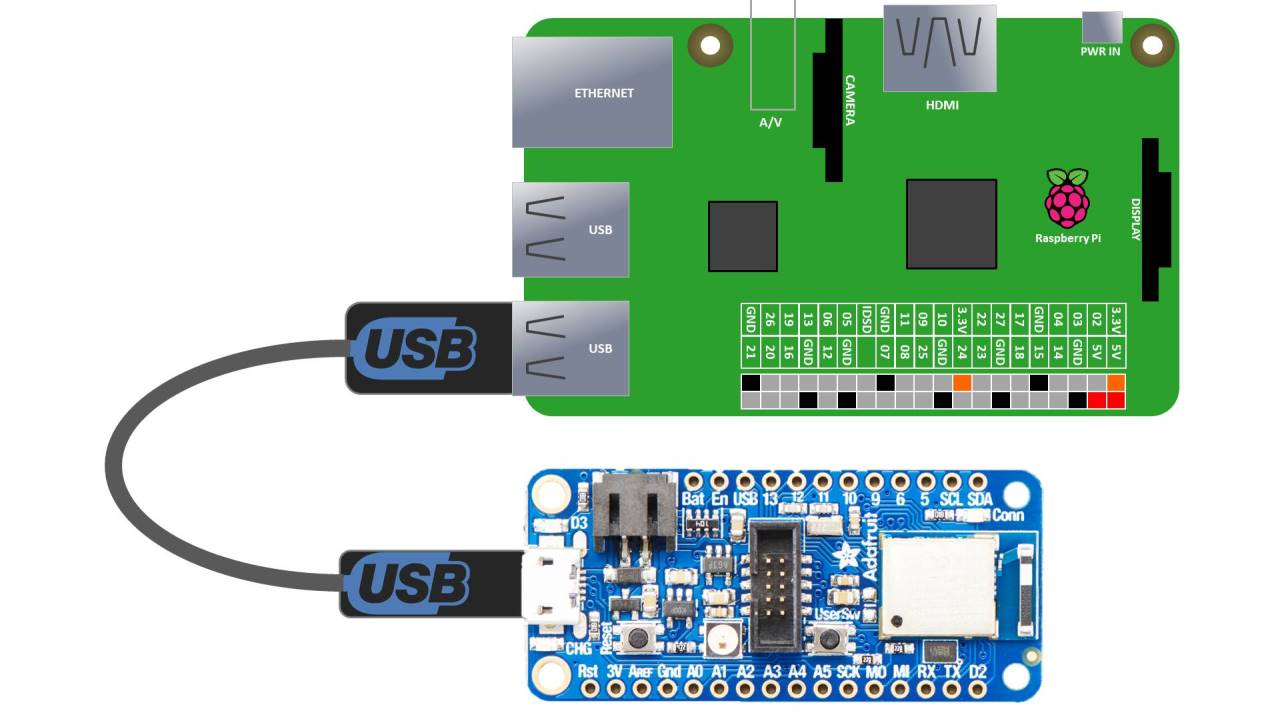
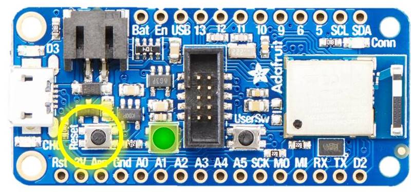
Double tap the reset button on the nRF52840 board. The NeoPixel should briefly turn red and then a solid green which indicates the board is in bootloader mode. You have to double tap quickly. A slow double tap is used to put the board in safe mode.
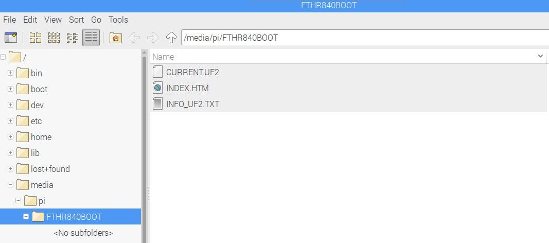
The Pi shoud recognize that a new USB removable media device has been connected and display the option to open in File Manager. The new media folder should be called called FTHR840BOOT. Current.UF2 is the current contents of the microcontroller flash. It can easily updated by just coping a new UF2 file to the folder.
 Update: The latest CircuitPython UF2 can now be downloaded from CircuitPython.org.
Once the download completes just copy the new UF2 file to the FTHR840BOOT folder. CircuitPython should now be installed on the nRF52840 board.
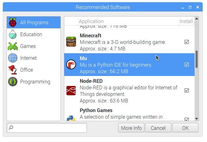
Adafruit recommends using Mu when starting CircuitPython development. Mu is a very simple intuitive cross platform Python editor that has excellent support for CircuitPython programming and file management. Of course you don’t have to use Mu. You can use any editor that writes out the file completely when you save, such as VS Code, Sublime and VIM. To install Mu, click the Raspberry Pi Main Menu – Preferences – Recommended Software. Then click the check box next to Mu and OK to install.
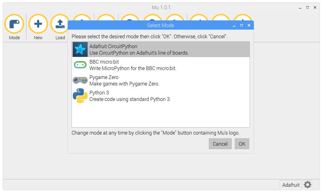
Once the installation completes click the Raspberry Pi Main Menu – Programming – Mu to run the program. On the first run, you should be prompted to select a Mode. Choose Adafruit CircuitPyton and click OK.
The Mu IDE is very intuitive.
- Mode – Changes the mode (CircuitPython, Microbit, Pygame Zero, Python 3)
- New – Creates a new file
- Load – Loads a file
- Save – Saves a file and automatically reloads and runs the code.
- Serial – Opens up the serial console and the REPL
- Zoom In & Zoom Out – Change the font size
- Theme – Changes the IDE skin
- Check – Tests your code for bugs
- Help – Opens the online help page
- Quit – Exits Mu
Here’s the CircuitPython code for a simple program that illuminates the built-in red LED on the board when the user switch is pressed.
import board
from digitalio import DigitalInOut, Direction, Pull
from time import sleep

led = DigitalInOut(board.RED_LED)
led.direction = Direction.OUTPUT
switch = DigitalInOut(board.SWITCH)
switch.direction = Direction.INPUT
switch.pull = Pull.UP

while True:
    led.value = not switch.value
    if led.value:
        print('switch pressed - LED on')
    sleep(.5)
The code is very similar to regular MicroPython. The board library contains definitions that are specific to each development board such as the Feather nRF52840 Express. The digitalio library is similar to the MicroPython Machine library or the rPI.GPIO library and lets you control GPIO pins. An interrupt would be preferable for the switch in the above code but CircuitPython doesn’t support interrupts or callbacks, yet. When saving the program use the filename code.py so it runs automatically (main.py should also work).
Another great feature of CircuitPython is that code written for a microcontroller such as the nRF52840 will also run on the Raspberry Pi with minor modifications. The Adafruit_Blinka library (named after the CircuitPython mascot) allows you to run CircuitPython on the Raspberry Pi and other boards such as the Orange Pi and the Beagle Bone. To install Adafruit_Blinka first make sure your Raspberry Pi has the latest version of Raspbian and run an update and upgrade.
sudo apt-get update && sudo apt-get upgrade
Next update setup tools.
sudo pip3 install --upgrade setuptools
Make sure rPi.GPIO is installed.
sudo pip3 install RPI.GPIO
Install Adafruit-Blinka
sudo pip3 install adafruit-blinka
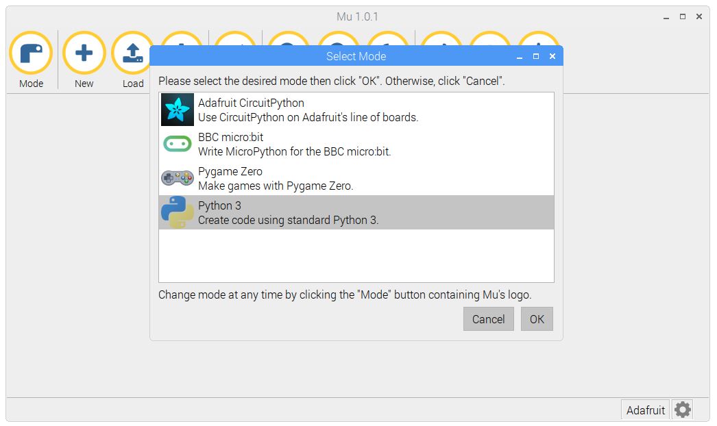
CircuitPython code should now work on the Pi. In Mu, click Mode and switch to Python 3.
Here is the previous code example. There are 2 changes. RED_LED was changed to D20 and SWITCH was changed to D21.
import board
from digitalio import DigitalInOut, Direction, Pull
from time import sleep
led = DigitalInOut(board.D20)
led.direction = Direction.OUTPUT
switch = DigitalInOut(board.D21)
switch.direction = Direction.INPUT
switch.pull = Pull.UP
while True:
    led.value = not switch.value
    if led.value:
        print('switch pressed - LED on')
    sleep(.5)
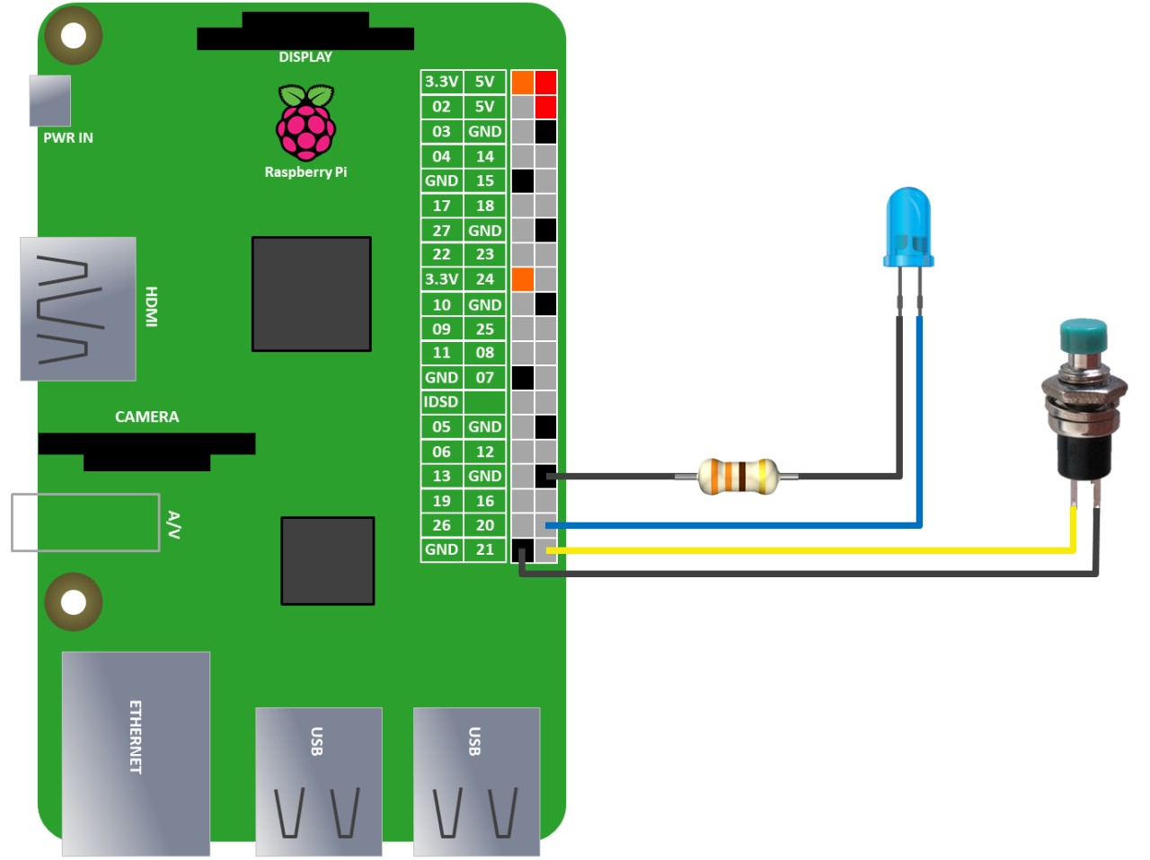
To mimic the nRF52840 board, an Led and a push button switch are connected to the the Pi. The LED anode is connected to GPIO 20 on the Pi. The LED cathode is connected to a ground pin with a 330Ω resistor in series to limit the current. One terminal of the switch is connected to GPIO 21. The other terminal is connected to ground
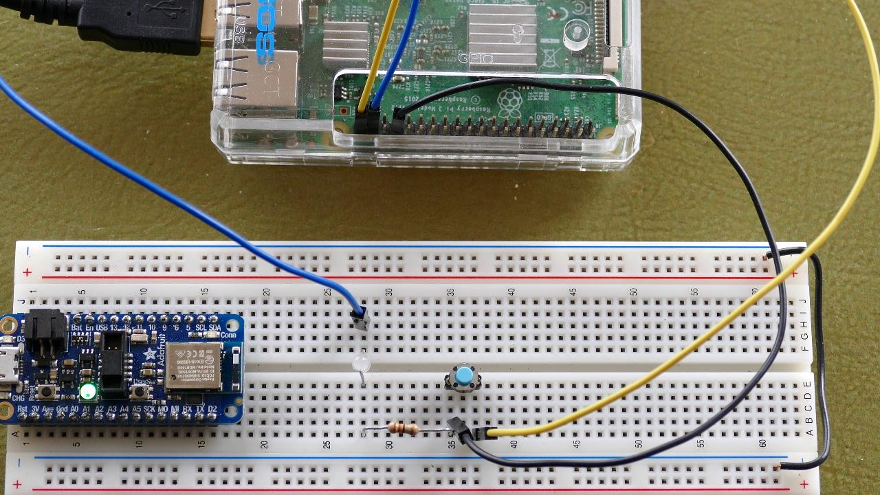
In Mu, click the Run button to start the program. Pressing the push button switch will pull GPIO 21 low to ground which will turn on the LED just like on the nRF52840 example. The ability to use the same code on the Pi and a microcontroller is very useful because if you create or download a CircuitPython library it should work across multiple devices. Doesn’t matter if it is I²C or SPI; it should be compatible.
In addition to the CircuitPython core, Adafruit provides a large bundle of libraries such as onewire, HID, and of course Bluetooth Low Energy which you can download from the Adafruit Circuitpython Bundle GitHub repo. The bundle includes the Adafruit_CircuitPython_BLE library. Here’s a quick BLE example. I rearranged the code from the video into a loop. The nRF52840 board waits for a connection and then waits for a message. Upon receipt the board echos the message back to the client and prints it to the console.
 UPDATE: Adafruit has made extensive changes to the CircuitPython BLE library. I have revised the code below appropriately.
from adafruit_ble import BLERadio
from adafruit_ble.advertising.standard import ProvideServicesAdvertisement
from adafruit_ble.services.nordic import UARTService

ble = BLERadio()
uart_server = UARTService()
advertisement = ProvideServicesAdvertisement(uart_server)

while True:
    ble.start_advertising(advertisement)  # Advertise when not connected.
    while not ble.connected:
        pass
    while ble.connected:
        if uart_server.in_waiting:
            msg = uart_server.read()
            print(msg)
            uart_server.write(msg)
My next tutorial demonstrates how to use OpenOCD and a Raspberry Pi to load CircuitPython on an inexpensive Nordic BlueTooth dongle.