
This tutorial demonstrates how to use character LCD and color TFT displays on the nRF52840 with CircuitPython. It explores the DisplayIO library and using Bluetooth low energy to interact with LCD displays from a mobile phone.
This is my 3nd CircuitPython tutorial. The first one demonstrated getting started with the Adafruit Feather nRF52840 Express and BLE. The 2nd one showed how to flash the Nordic nRF52840 dongle using OpenOCD on a Raspberry Pi and create BLE applications.
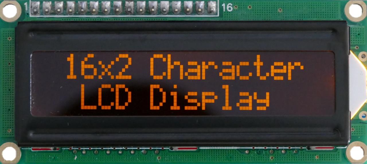
This tutorial will start by connecting a character LCD display to a Nordic nRF52840 dongle. Below is a 16×2 character LCD display. It’s very legible, easy to connect and great for providing user feedback. They come in different sizes and colors. They’re inexpensive and can also readily be salvaged from old electronic equipment such as phones, printers, faxes, etc.
The display interface uses 4 bit mode which requires 6 GPIO pins. Two potentiometers are added to control contrast and brightness. The LCD ground pin is connected to a ground on the dongle. The Read/Write pin (RW) is grounded to ensure write only. The 3.3 V dongle could potentially be damaged if you tried to read the 5 V display. The backlight cathode is grounded and 1 terminal from each pot is grounded. The display Vcc is connected to Vbus on the dongle which is the USB 5 V bus. The other terminal from each pot is also connected to 5 V. This causes the pots to act as variable voltage dividers between 0 and 5 V. The wiper from the first pot is connected to the LCD display contrast pin. The wiper from the other pot is connected to the backlight anode which will control brightness. The RS pin is connected GPIO 0.13. Enable is connected to 0.15. Data lines D4, D5, D6 and D7 are connected to 0.17 0.20, 0.22 and 0.24 respectively.
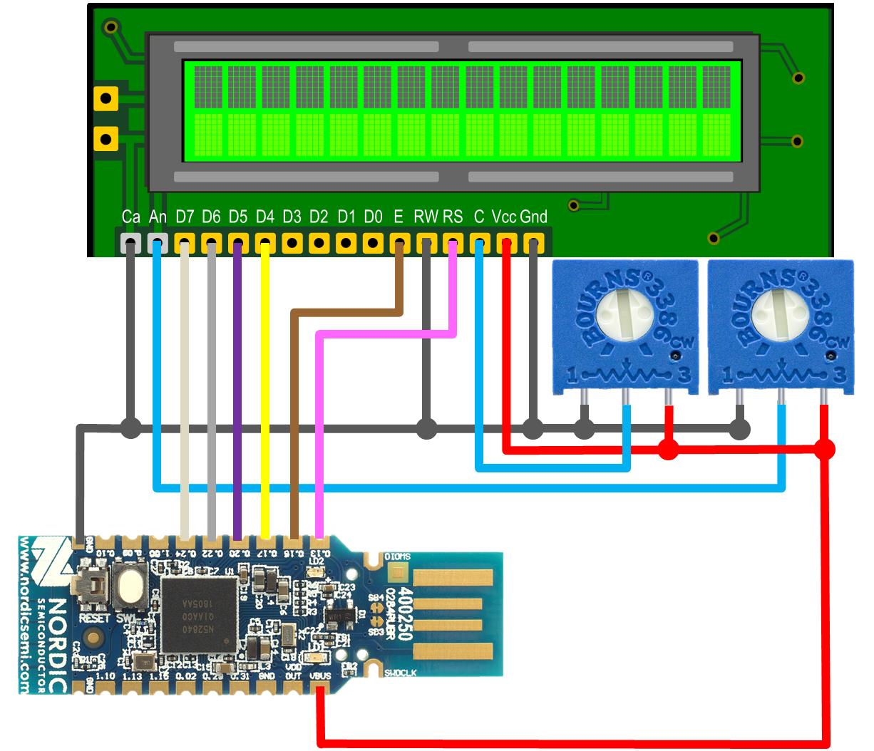
By the way, it doesn’t really matter which GPIO pins you use for the display control and data lines because any available pins can be specified in the code.
The Adafruit CircuitPython bundle contains the CharLCD library which can be used to control character LCD displays. Copy the adafruit_character_lcd folder from the bundle to the Nordic dongle which appears as a USB drive labelled CircuitPy. The following code displays a message on the display and after a few seconds the text is shifted off to the right.
import board
from digitalio import DigitalInOut
from time import sleep
from adafruit_character_lcd.character_lcd import Character_LCD_Mono

lcd_rs = DigitalInOut(board.P0_13)
lcd_en = DigitalInOut(board.P0_15)
lcd_d4 = DigitalInOut(board.P0_17)
lcd_d5 = DigitalInOut(board.P0_20)
lcd_d6 = DigitalInOut(board.P0_22)
lcd_d7 = DigitalInOut(board.P0_24)

lcd_columns = 16
lcd_rows = 2

lcd = Character_LCD_Mono(lcd_rs, lcd_en, lcd_d4, lcd_d5, lcd_d6, lcd_d7,
                         lcd_columns, lcd_rows)
lcd.clear()
lcd.message = "nRF52840-dongle\nCircuitPython!"
sleep(4)

for x in range(16):
    lcd.move_right()
    sleep(.2)
Next we’ll make the display more interactive with Bluetooth low energy (BLE). From the CircuitPython bundle copy the adafruit_ble folder to the dongle. Only a few modifications to the existing code are necessary.
 UPDATE: Adafruit has made extensive changes to the CircuitPython BLE library. I have revised the code below appropriately.
import board
from digitalio import DigitalInOut
from adafruit_character_lcd.character_lcd import Character_LCD_Mono
from adafruit_ble import BLERadio
from adafruit_ble.advertising.standard import ProvideServicesAdvertisement
from adafruit_ble.services.nordic import UARTService

lcd_rs = DigitalInOut(board.P0_13)
lcd_en = DigitalInOut(board.P0_15)
lcd_d4 = DigitalInOut(board.P0_17)
lcd_d5 = DigitalInOut(board.P0_20)
lcd_d6 = DigitalInOut(board.P0_22)
lcd_d7 = DigitalInOut(board.P0_24)

lcd_columns = 16
lcd_rows = 2

lcd = Character_LCD_Mono(lcd_rs, lcd_en, lcd_d4, lcd_d5, lcd_d6, lcd_d7,
                         lcd_columns, lcd_rows)

lcd.clear()
lcd.message = '  Waiting for\n  Connection...'

ble = BLERadio()
uart_server = UARTService()
advertisement = ProvideServicesAdvertisement(uart_server)

while True:
    ble.start_advertising(advertisement)  # Advertise when not connected.
    while not ble.connected:
        pass

    lcd.clear()
    lcd.message = ' Listening for\n Messages...'

    while ble.connected:
        if uart_server.in_waiting:
            msg = uart_server.read().decode('utf-8').rstrip()
            lcd.clear()
            lcd.message = msg
            uart_server.write('Message displayed.')
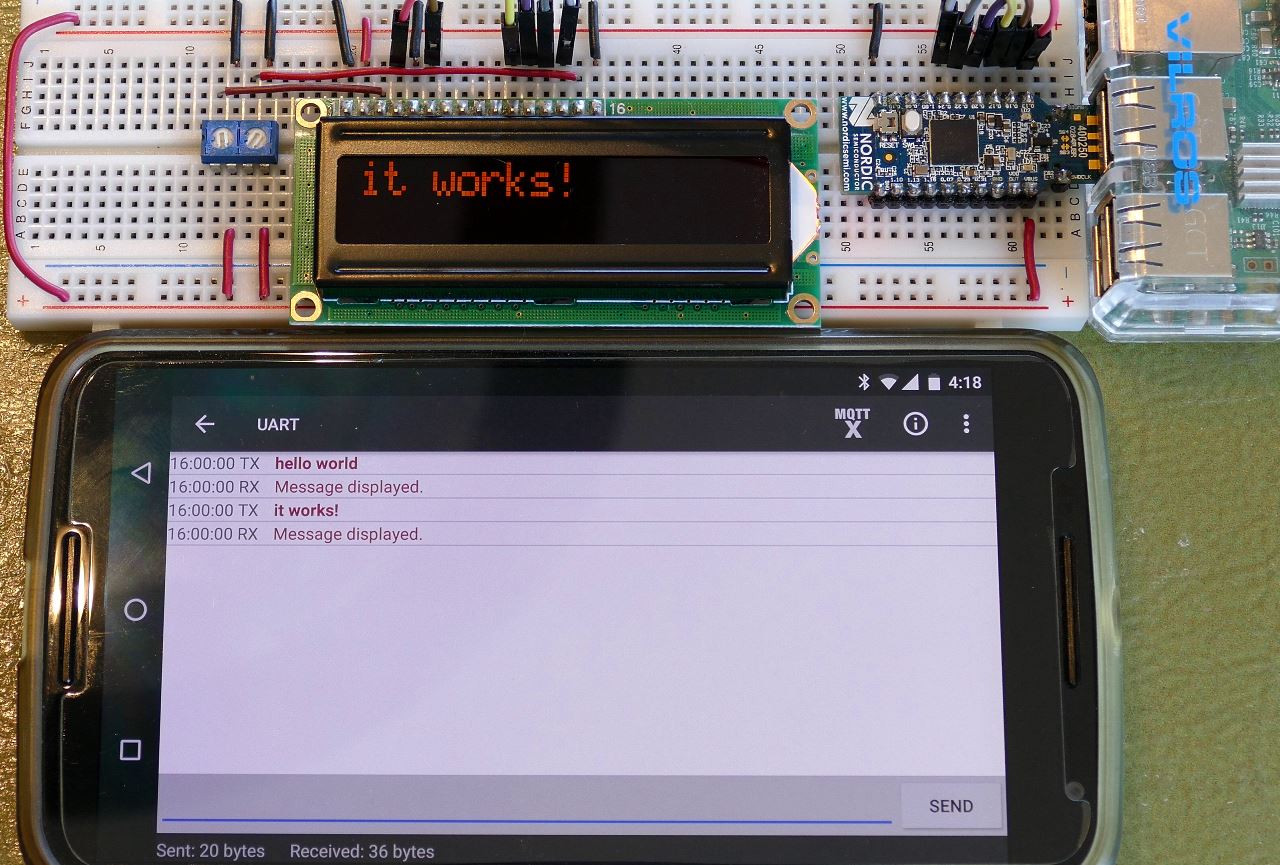
The code sets up a UART server and waits for BLE connections. Once connected the main program loop checks for incoming messages. The message text is displayed on the LCD and an acknowledgment is returned to the BLE client. The Adafruit Bluefruit LE Connect app can be used to connect from a mobile phone (both Android and iOS .)
In my previous MicroPython OLED tutorial I created a MicroPython library for the SSD1351 display and a simple brick game.
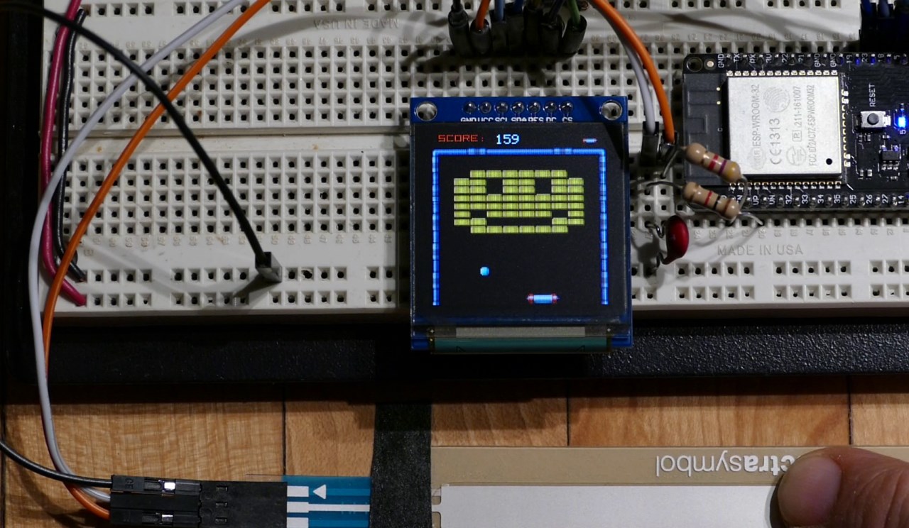
I updated my SSD1351 library so it’s CircuitPython compatible. I’ve also included a couple of CircuitPython examples. The SSD1351 library and all the demos can be downloaded on my GitHub page. One of the new examples is a simple maze demo.
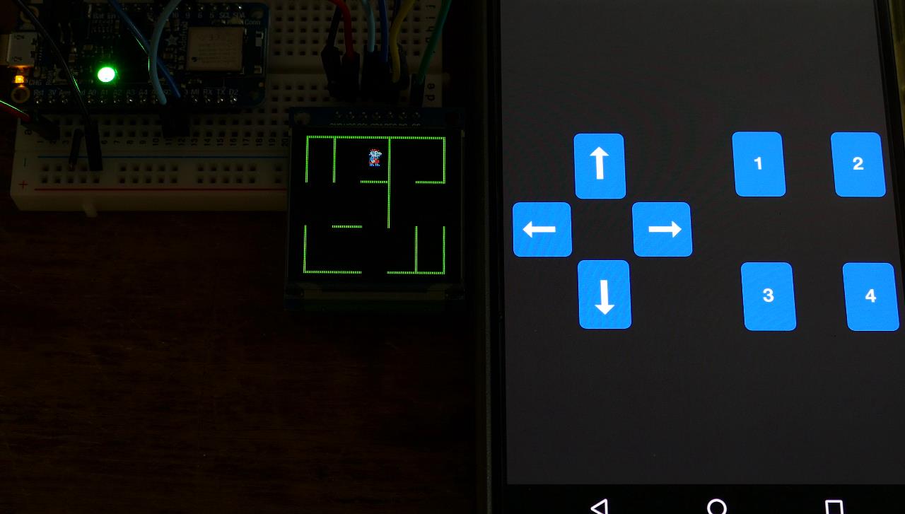
Instead of a wired slider, the main character is controlled wirelessly using the control pad that’s included with the Adafruit Bluefruit LE Connect app. I designed the library to be performant but it’s all coded in MicroPython. If I were to add a lot of monsters, weapons and other props, the animation might not be so fluid. Fortunately, CircuitPython provides a native LCD library called DisplayIO which has many great features such as tilesets which can be used for sprites or bitmap fonts. There are groups which can organize different layers of graphics. Layers can have transparent backgrounds so they can be stacked on top of other layers. The DisplayIO library is currently very beta. It’s a work in progress and the code is in flux.
DisplayIO is adding support for many graphical LCD displays. One that is currently supported is the ST7735.
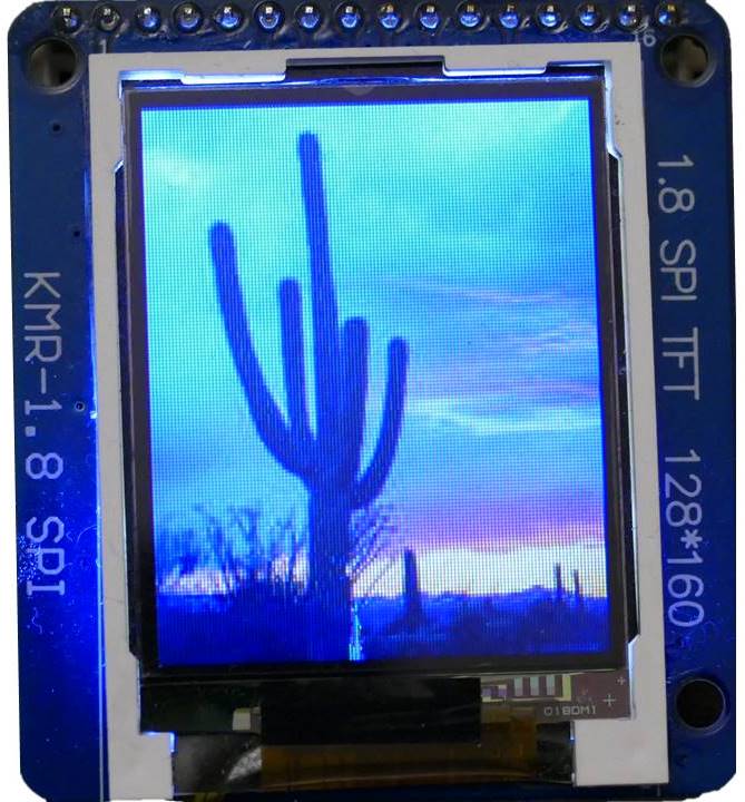
It’s an inexpensive 16 bit color TFT graphic LCD display. It comes in different sizes and resolutions. This one is 1.8 inch (128 by 160 pixels.) There’s a fast SPI interface which makes it easy to connect to most IOT devices. It operates at 3.3 V so it’s compatible with the nRF52840.
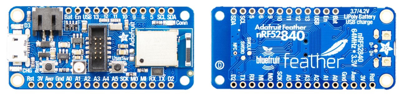
For the next demo, I’ll switch to an Adafruit Feather nRF52840 Express board because I encountered hardware crashing using the Nordic dongle. Using the DispalyIO library, the SPI library, the Bluetooth library and the DHT library probably was too much for the dongle which has less memory than the Feather.
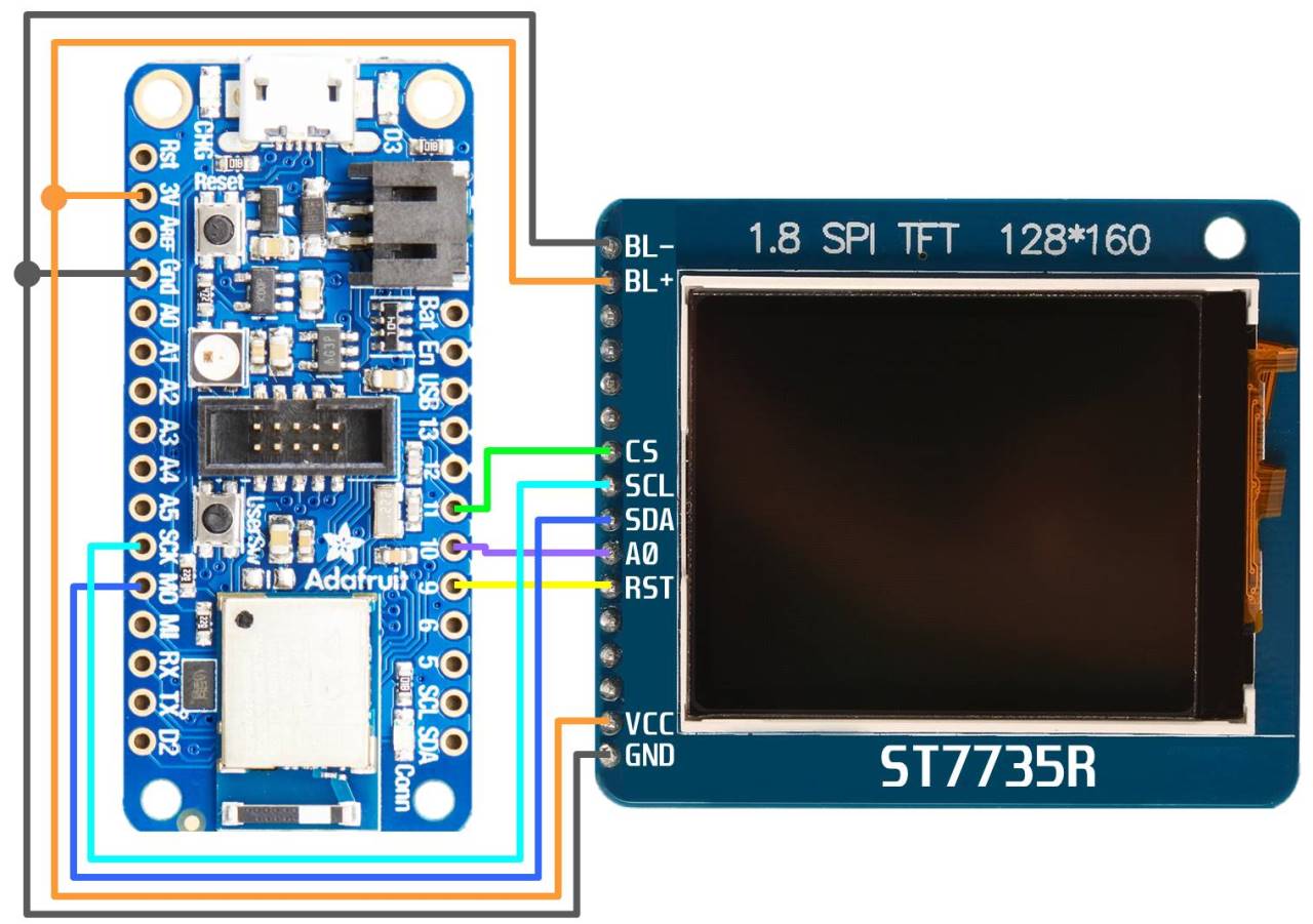
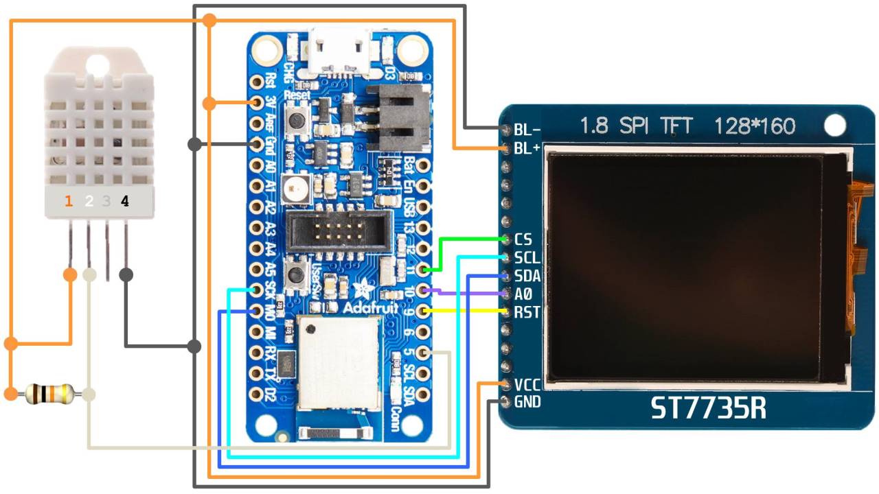
The ST7735 ground is connected to a ground on the Feather. Vcc is connected to 3.3 V. RST (Reset) is connected to GPIO 9. A0 which toggles between data and command mode is connected to GPIO 10. SDA is connected to MO (Master Out Slave In). SCL is connected SCK (Serial clock). CS (Chip Select) is connected to GPIO 11. The backlight LED anode is connected to 3.3 V. The backlight cathode is connected to ground.
A DHT22 sensor will provide temperature and humidity data.
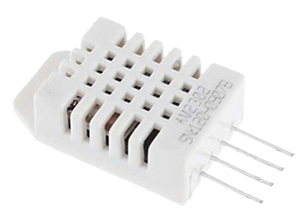
The DHT22 ground pin is grounded. The DHT22 Vcc pin is connected to 3.3 V. The data pin is connected to GPIO 5. A 10 KΩ pull up resistor is placed across the data line and 3.3 V. It looks like the pull-up is automatically set now for the GPIO pin so the 10 KΩ resistor is no longer necessary. As with the character LCD display wiring, you can use different GPIO pins, although I would stick with the dedicated MOSI and serial clock pins if your board has them because it makes coding easier.
The ST7735 DisplayIO driver is currently separate from the CircuitPython bundle. Download the driver and copy it to the Feather. There are several variants of the ST7735 so it may be necessary to modify the init sequence. On my ST7735R I had to change command 0x20 (inversion off) to 0x21 (inversion on.) I also had to the change the MADCTL 0x36 (memory data access control) data from 0x18 to 0xC8 to vertically flip the display. Please note that Adafruit now provides a separate ST7735R library.
_INIT_SEQUENCE = bytearray(
    b"\x01\x80\x96" # SWRESET and Delay 150ms
    b"\x11\x80\xff" # SLPOUT and Delay
    b"\xb1\x03\x01\x2C\x2D" # _FRMCTR1
    b"\xb2\x03\x01\x2C\x2D" # _FRMCTR2
    b"\xb3\x06\x01\x2C\x2D\x01\x2C\x2D" # _FRMCTR3
    b"\xb4\x01\x07" # _INVCTR line inversion
    b"\xc0\x03\xa2\x02\x84" # _PWCTR1 GVDD = 4.7V, 1.0uA
    b"\xc1\x01\xc5" # _PWCTR2 VGH=14.7V, VGL=-7.35V
    b"\xc2\x02\x0a\x00" # _PWCTR3 Opamp current small, Boost frequency
    b"\xc3\x02\x8a\x2a"
    b"\xc4\x02\x8a\xee"
    b"\xc5\x01\x0e" # _VMCTR1 VCOMH = 4V, VOML = -1.1V
    b"\x21\x00" # _INVON
    b"\x36\x01\xC8" # _MADCTL
    # 1 clk cycle nonoverlap, 2 cycle gate rise, 3 sycle osc equalie,
    # fix on VTL
    b"\x3a\x01\x05" # COLMOD - 16bit color
    b"\xe0\x10\x02\x1c\x07\x12\x37\x32\x29\x2d\x29\x25\x2B\x39\x00\x01\x03\x10" # _GMCTRP1 Gamma
    b"\xe1\x10\x03\x1d\x07\x06\x2E\x2C\x29\x2D\x2E\x2E\x37\x3F\x00\x00\x02\x10" # _GMCTRN1
    b"\x13\x80\x0a" # _NORON
    b"\x29\x80\x64" # _DISPON
)
A couple more libraries from the bundle are also required. Copy the adafruit_ble and adafruit_dht libraries from the bundle to the Feather. The demo uses a background picture which needs to be in bitmap format and sized to 128×160 pixels like the following.

The following boiler plate code sets up DisplayIO to work with the ST7735.
import board
import displayio
from adafruit_st7735r import ST7735R

spi = board.SPI()
cs = board.D11
dc = board.D10
rst = board.D9

displayio.release_displays()
display_bus = displayio.FourWire(spi, command=dc, chip_select=cs, reset=rst)
display = ST7735R(display_bus, width=128, height=160)
By the way, there are CircuitPython boards that have built-in displays such as the PyPortal. They don’t require the above initialization code. The displays can be driven simply by referencing board.display.
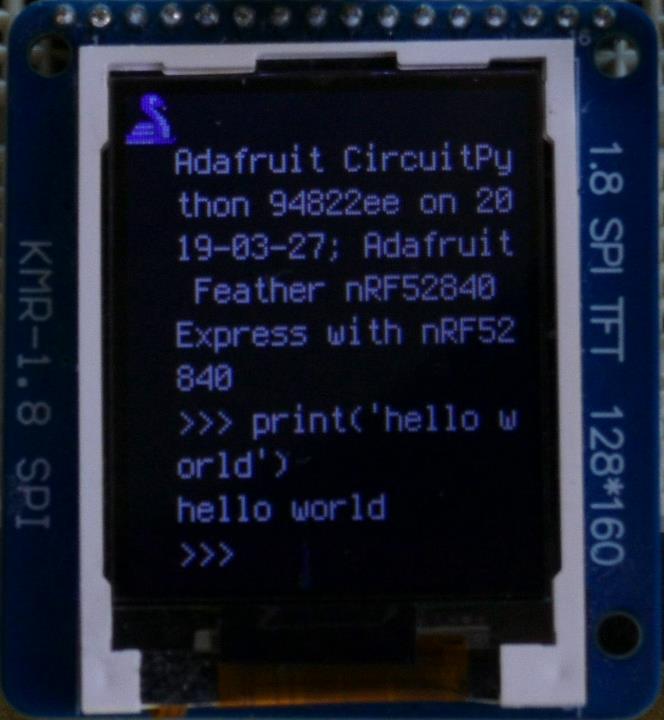
One very cool feature of the DisplayIO library is that when your code isn’t running it will automatically pipe the serial console to the display. Therefore, even though the above program doesn’t have any drawing commands, text or bitmaps yet, it’s still enough to test if the display works. Just run the program and then click Serial and enter the REPL. The display should echo everything you type and show the serial output.
Next the code will be updated to add a background image, terminal text, a DHT22 sensor and BLE support.
 UPDATE: Adafruit has made extensive changes to the CircuitPython BLE library. I have revised the code below appropriately.
import board
import displayio
from adafruit_st7735r import ST7735R
from adafruit_dht import DHT22
from terminalio import FONT, Terminal
from time import sleep
from adafruit_ble import BLERadio
from adafruit_ble.advertising.standard import ProvideServicesAdvertisement
from adafruit_ble.services.nordic import UARTService

ble = BLERadio()
uart_server = UARTService()
advertisement = ProvideServicesAdvertisement(uart_server)

dht = DHT22(board.D5)  # Initialize the DHT22

spi = board.SPI()
cs = board.D11
dc = board.D10
rst = board.D9

displayio.release_displays()
display_bus = displayio.FourWire(spi, command=dc, chip_select=cs, reset=rst)
display = ST7735R(display_bus, width=128, height=160)

splash = displayio.Group()
display.show(splash)

with open("/Scene9.bmp", "rb") as f:
    bmp = displayio.OnDiskBitmap(f)
    background = displayio.TileGrid(bmp,
                                    pixel_shader=displayio.ColorConverter(),
                                    x=0, y=0)
    splash.append(background)

    palette = displayio.Palette(2)
    palette.make_transparent(0)
    palette[1] = 0x00FF00
    w, h = FONT.get_bounding_box()
    foreground = displayio.TileGrid(FONT.bitmap, pixel_shader=palette,
                                    x=2, y=0,
                                    width=21, height=5,
                                    tile_width=w, tile_height=h)

    terminal = Terminal(foreground, FONT)
    splash.append(foreground)

    while True:
        try:
            if not ble.connected and not ble.advertising:
                ble.start_advertising(advertisement)  # Advertise when not connected.

            t = dht.temperature
            h = dht.humidity
            if isinstance(t, float) and isinstance(h, float):
                terminal.write("\r\n{:.1f}'C".format(t))
                terminal.write("{:>13.1f}%".format(h))
                if ble.connected:
                    uart_server.write('{0},{1}\n'.format(t, h))
                sleep(3)
            else:
                print('Invalid reading.')
                sleep(5)
        except RuntimeError as error:
            print(error.args[0])  # Bad DHT22 reading
            sleep(5)
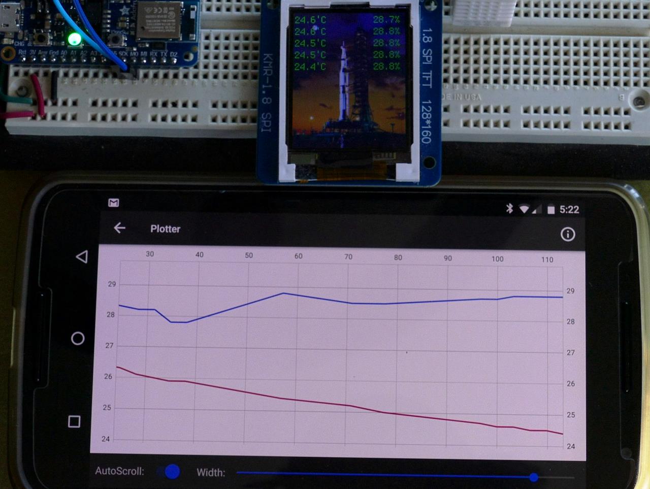
The bitmap fills the background and the sensor temperature and humidity readings scroll over in a transparent terminal overlay.
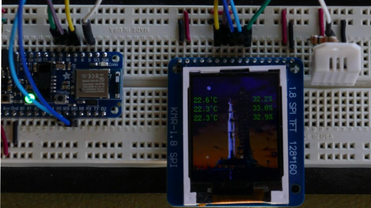
The Bluefruit LE Connect app can now connect to the display. The plotter feature charts the temperature and humidity data from the DHT22 sensor.
My next tutorial demonstrates how to add Internet access to an nRF52840 board running CircuitPython by using an ESP32 as a WiFi coprocessor.