
In this quick tutorial I’ll repair an Insteon PowerLinc modem. The PLM is a USB home automation interface that connects to a computer such as a Raspberry Pi and can be used to operate lights, electrical devices, thermostats, monitor sensors and more. The PLM uses dual band communication, meaning it can send control signals wirelessly and via the electrical power lines in your home.
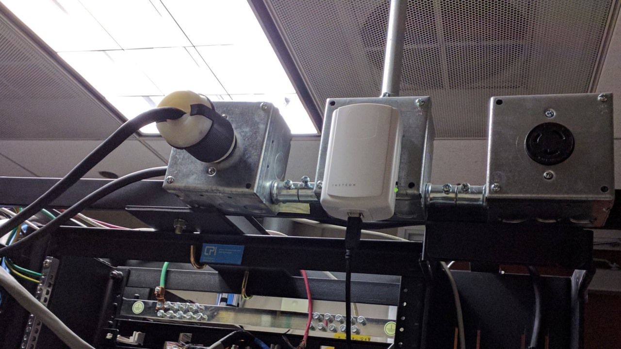
In 2014, I posted a tutorial showing how I automated the fountain in my office lobby using a Raspberry Pi, a float sensor and 3 Insteon modules.
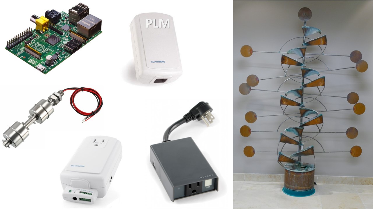
The fountain turns on during business hours. However, if the water level is low the fountain shuts off and notifies the staff by email. This prevents the pump from burning out. The system has been running great, until today. This morning the fountain was off and the PLM was not responding.
 Warning: the PLM uses potentially lethal voltages. Please exercise the appropriate caution and if you are unsure check with an electrician or electrical engineer because you could get hurt or burn down your home.
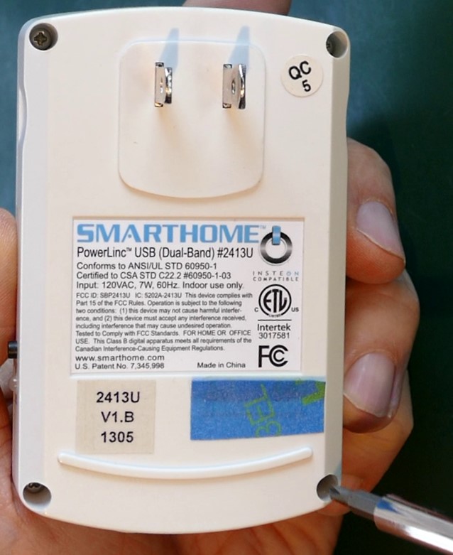
Here’s the defective PLM. It’s a model 2413U version 1B (made in China, ETL listed, FCC ID SBP2413U). It’s held together with only 4 screws which facilitates disassembly.
Insteon products have been around since 2005. When they first came out they were somewhat unreliable. Supposedly they’re better now. Although there’s a long thread on the Universal Devices forum that suggests they are still using low quality components; especially electrolytic capacitors. I purchased this PLM in 2013 so it lasted almost 5 years. However, it has been kept in a locked, air conditioned server room and mounted with lots of isolation. The electrical supply is also well regulated (basically ideal conditions).
The above mentioned forum thread currently has around 100 users with failed PLM’s and suggests a lifetime closer to 2.5 years in more common home environments.
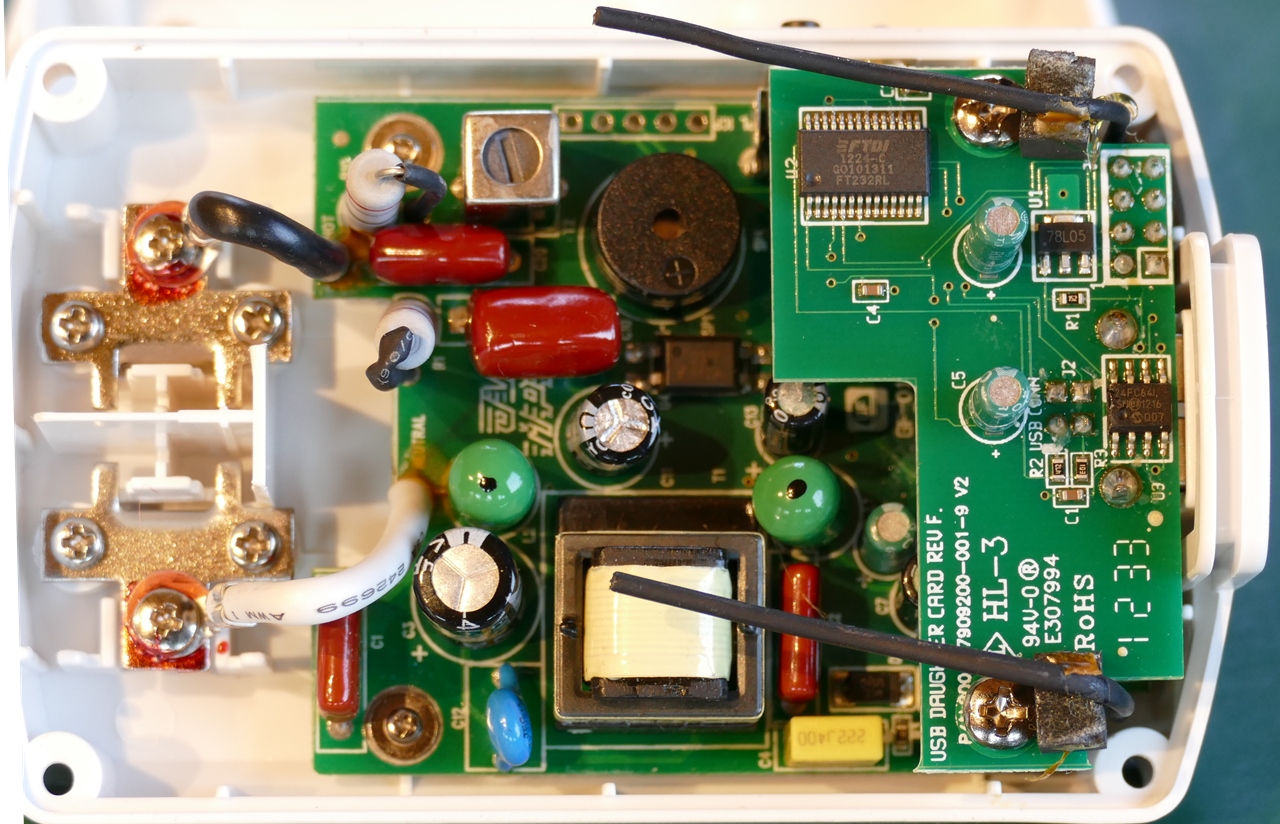
There are 2 boards inside the PLM. A main board and a daughter board on top. The main board contains the power supply. There is no fuse but there are 2 vertical resistors that are probably fusible, which acts like a fuse. The PLM comes in a USB and a serial version. The daughter board probably can be swapped out to make different versions.
Before troubleshooting a device for the first time, I usually check the web, but a Google search for the schematic came back empty-handed. Another great place to look is the FCC database. Unfortunately, the schematics are withheld for confidentiality reasons but there is a block diagram available.
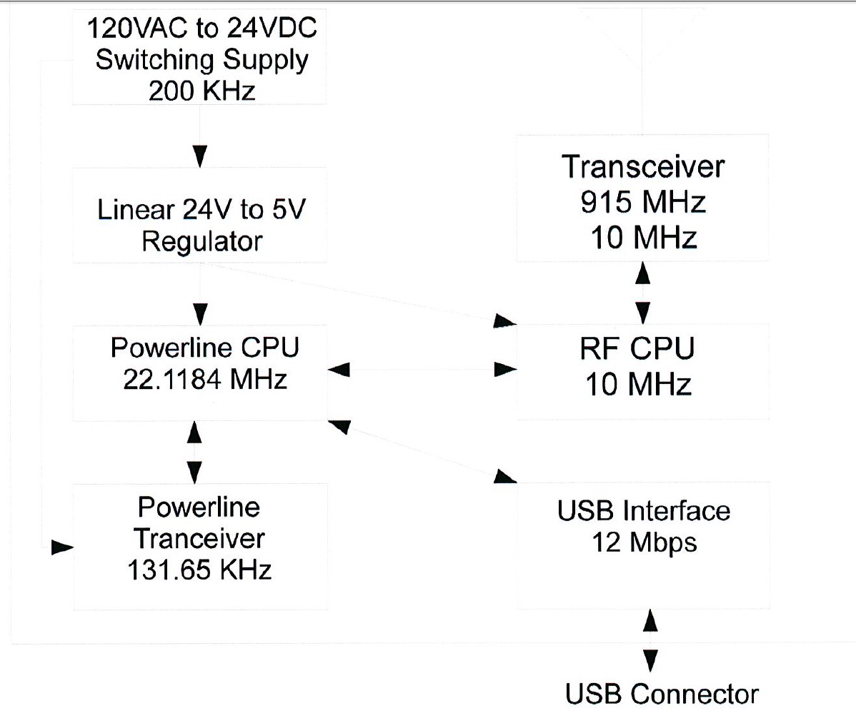
The diagram gives a good overview. There’s a switching power supply operating at 200 KHz which drops the 120 VAC down to 24 VDC. Then a linear voltage regulator drops the 24 VDC down to 5 VDC. The fault is likely in the switching power supply because it contains several electrolytic caps.
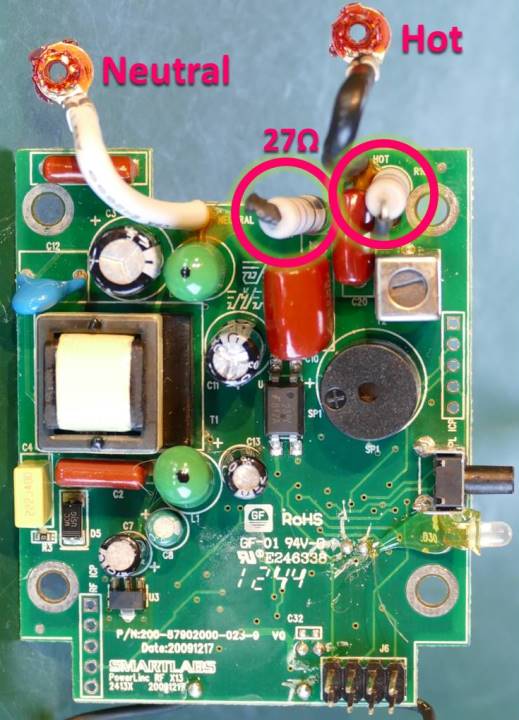
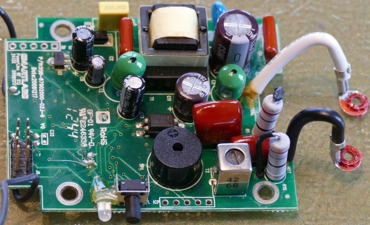
The board is a combination of through-hole and surface mount. There’s a 2009 date on the PCB but I see some 2012 date codes on the IC’s which corresponds with my purchase date in 2013. The white neutral and black hot mains wires are soldered to the PCB with a little glue at the base. Two 27 ohm resistors are placed in series with the hot. In addition to likely being fusible, they are probably inrush resistors designed to throttle the startup current which protects components such as the rectifier as the high voltage caps charge.
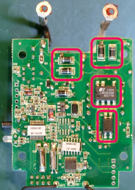
The bottom of the board, does not look good. There’s a lot of flux residue, corrosion, cold solder joints and excessive solder. The production is very shoddy especially for a mature product. The mains are connected to 4 surface mount diodes D1 to D4 that comprise a full-wave bridge rectifier. It converts the mains AC voltage to DC. The high voltage DC output feeds an LNK354 switched power source chip U1. It drops the voltage down to around 24 V. An opto-coupler U2 provides isolated feedback to the IC.
 Warning: discharge capacitors before handling or testing.
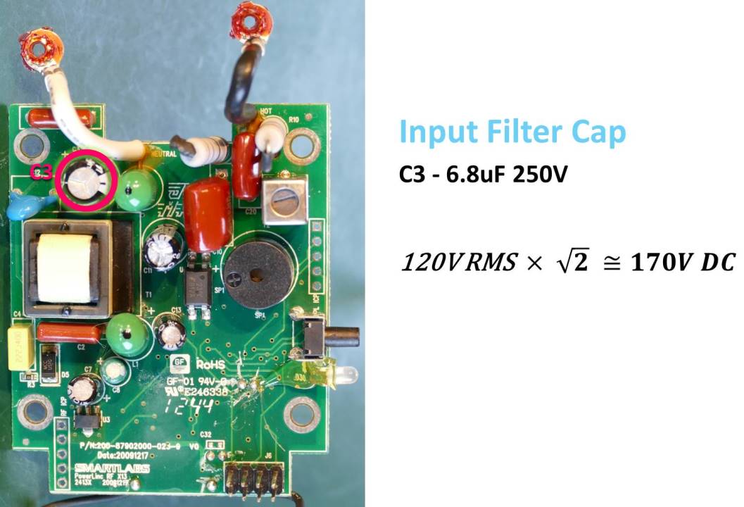
On the front of the board, a 6.8 uF 250 V cap (C3) provides input filtering for the power supply. The voltage rating is a little low. I like to derate caps by at least 50% which aids longevity and provides a safety margin in case of surges. My mains are 120 VAC RMS. Multiply that by the square root of 2 gives 170 VDC, after the rectifier under ideal conditions. The actual voltage will be lower because of the diodes, ripple and the inrush resistor. A cap rated for 350 V would be preferable (doubling 170 V and picking the next highest standard cap value).
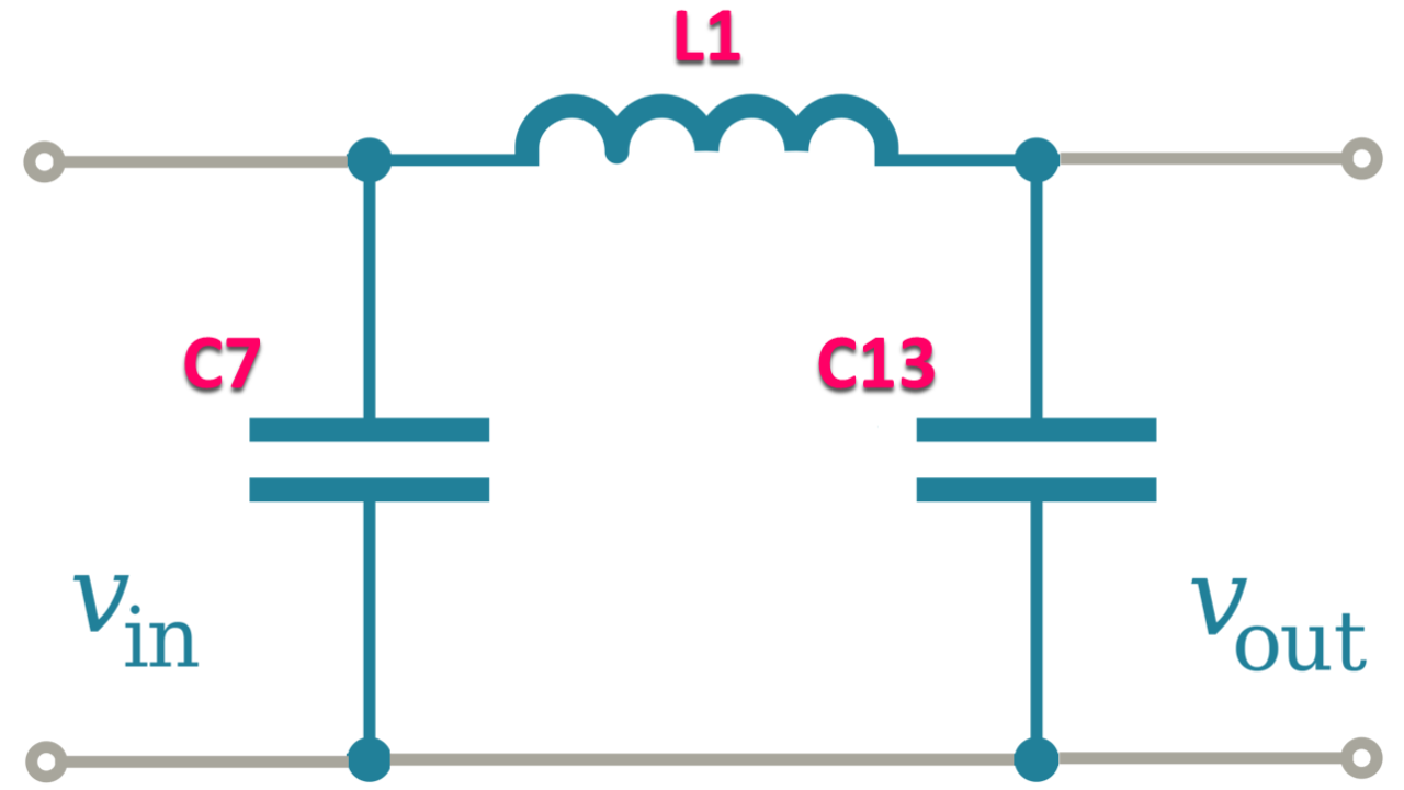
On the low voltage output side of the switched power source is a Pi filter comprised of two 10 uF 35 V caps (C7 & C13) and an inductor (L1). In newer PLM’s, these 10 uF caps may be replaced with 100 uF versions.
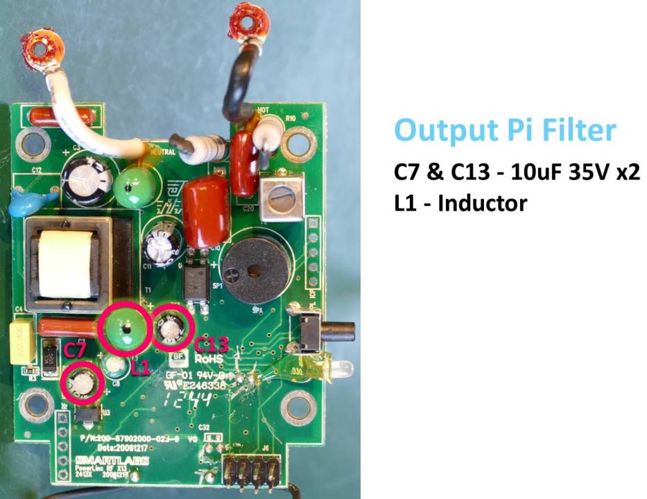
It called a Pi filter because the components on the schematic look like the Pi symbol.
The filter’s a good solution to attenuate noise on the power lines. Both the input and output filter caps are critical to the operation of the power supply and are likely culprits for the failure.
There are a total of 7 electrolytic caps on the main and daughter boards and they all look like low quality brands which appears to be endemic of Insteon products.
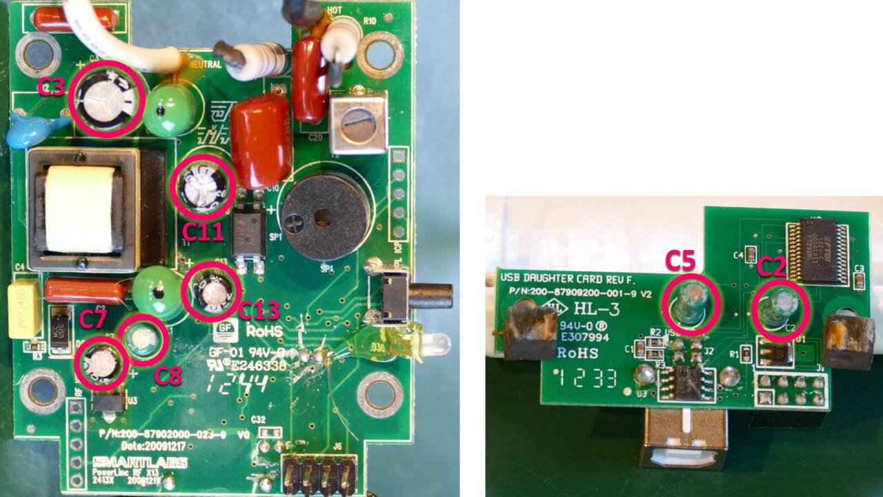
The high voltage input cap is very suspect. Looks like it’s a CA or CIA brand which I’ve never seen before. The 2 caps on the Pi filter are also suspect. They’re Samcon brand which I presume is Chinese or Taiwanese. The remaining 4 caps are Fujicon which I’m sure intentionally sounds Japanese but it’s not. Both Samcon and Fujicon are on the list of bad cap manufactures on the Bad Caps forum.
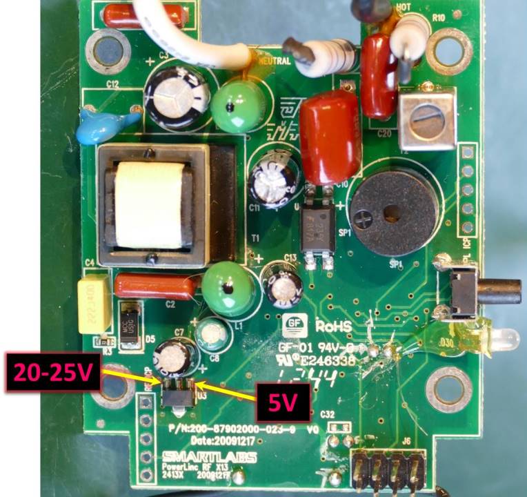
Normally I would start troubleshooting by testing electrolytic caps with an ESR meter and checking voltage points on the board. For example the linear voltage regulator (U3) should have around 20 V to 25 V on the input pin and 5 V on the output pin.
However, after browsing the automation forums I think there is a high probability that just replacing the 7 electrolytic caps should fix the modem. There’s no point in just replacing the bad ones because they’re all sketchy brands and are likely to eventually fail.
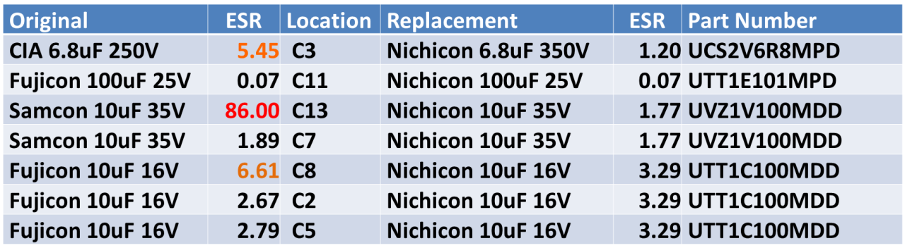
I replaced the 7 electrolytic caps with high quality Japanese caps (Nichicon brand). I tested the old caps with an ESR meter and 3 of them look bad. The worst was C13 from the Pi filter which was 86 ohms. Compare that to its identical sister cap at 1.89 ohms. This is probably the source of the failure.
You do not need to remove the caps to test them with an ESR meter. However, you may get misleading readings in certain cases such as when capacitors are in parallel or in series with an inductor as is the case with a Pi filter. In these cases it would be better to desolder the cap or at least desolder the positive lead.
There a lot of counterfeit capacitors online so I recommend you only buy from a reputable distributor such as Mouser, DigiKey or Farnell. There are a lot of strong opinions regarding cap quality but generally speaking I think most people would agree that Japanese capacitors such as Nichicon, Panasonic, Rubycon and United Chemicon are good quality. I recommend you select low ESR capacitors for the replacements.
Here’s the main board with the new caps.
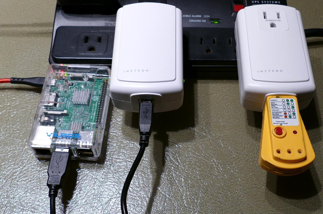
After reassembly, I reset the PLM to factory default settings and relinked the other modules in case the PLM’s database became corrupt. A Python library called Pylights can be used to test the modem using a Raspberry Pi. The PLM is plugged into the Pi using a standard USB cable.
Pylights is the library I used for my fountain automation. It utilizes 2 files. The first is devices.xml which allows you to designate friendly names for the Insteon modules instead of referencing them by their hex ID numbers. The following XML file substitutes the name appModule for the above appliance module with hex ID 12.AB.34.
<?xml version="1.0" ?>
<Devices>
	<Device>
		<name>Outdoor 2634 Appliance Module-</name>
		<shortName>appModule</shortName>
		<devType>Switch</devType>
		<address>12.AB.34</address>
		<level>255</level>
	</Device>
</Devices>
The 2nd file is pylights.py which is the Python library. The following test code turns on the appliance module called appModule for 3 seconds and then turns it off.
from time import sleep
import pylights
pylights.device_cfg_filename = 'devices.xml'
p = pylights.plm()
p.setLevel('appModule', 100)  # Turn on appliance
sleep(3)
p.setLevel('appModule', 0)    # Turn off appliance
Downloads:
Insteon Modem Developer’s Guide (10-12-2007)