
In this tutorial I will repair a PC with a corrupt UEFI BIOS.
The broken computer is made by Digital Storm which is a Silicon Valley company specializing in performance computers. This model has an Intel i7-6850K CPU running at 4 GHz with 32 GB of DDR4 RAM and a GTX 1080 graphics card.
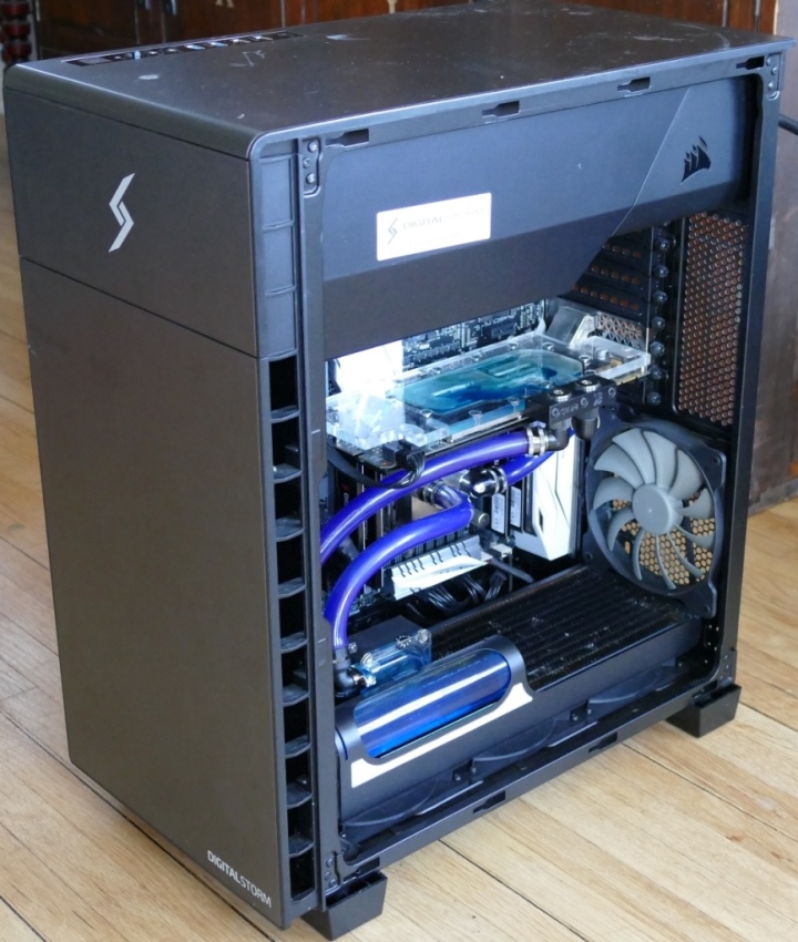
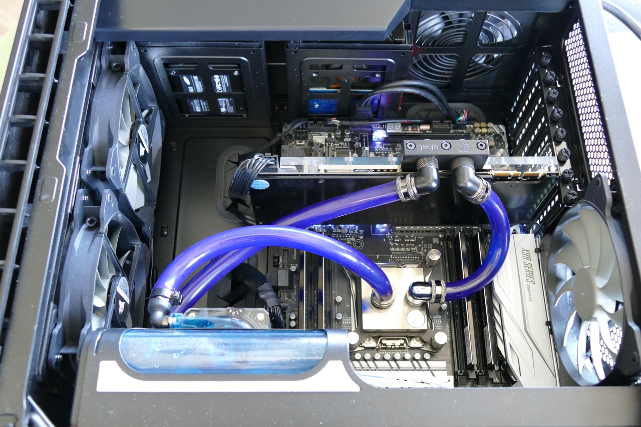
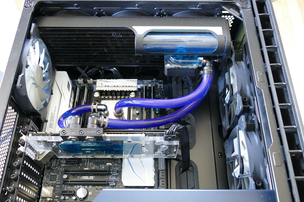
The motherboard is an Asus X99-A II. Both the CPU and the graphics card are liquid cooled.
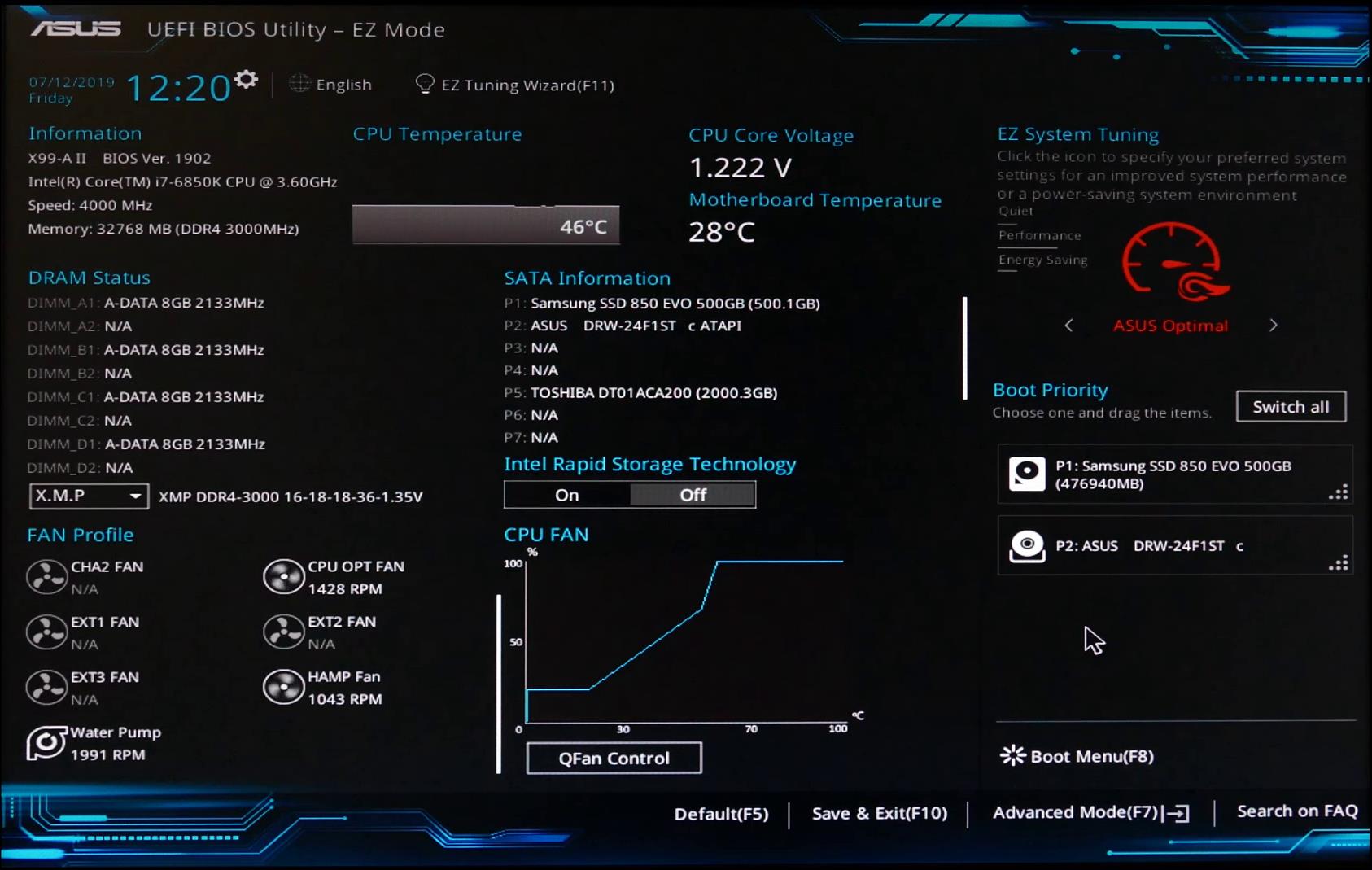
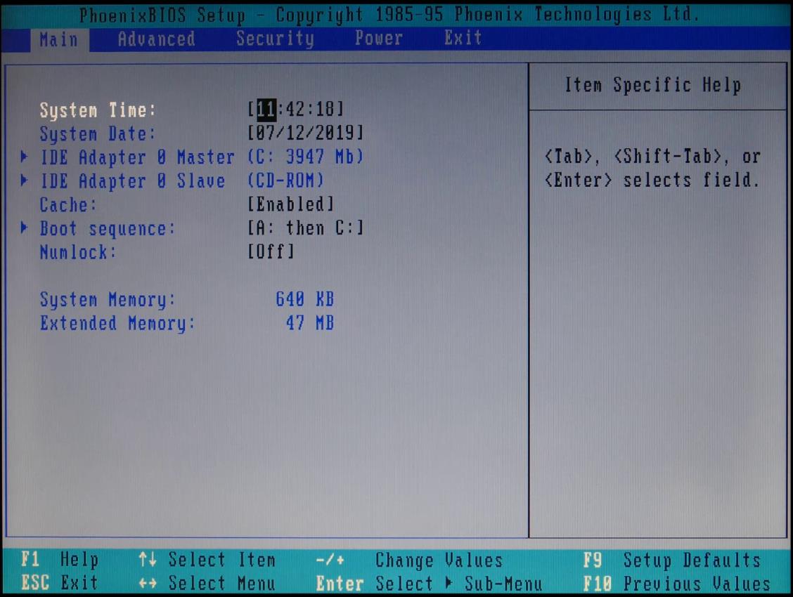
The computer is stuck in a rebooting loop. Upon power up, the computer lights up, fans spin and the coolant starts pumping. However, a few seconds later it shuts off. After a few more seconds it powers back on by itself and the loop repeats. The computer is not getting past the POST (Power On Self-Test) so the CMOS is not accessible.
I called Digital Storm tech support. We disconnected all the peripherals, spent a lot of time moving RAM sticks around, tested the power supply, disconnected the CPU and removed the graphics card. None of the aforementioned corrected the rebooting loop. Their conclusion was a bad motherboard (out of warranty) and they estimated $500 to fix it (includes shipping) assuming that it was the actual problem.
A little online research indicated that reboot loops are a common problem with the ASUS X99 motherboard and one possible cause is a corrupt BIOS firmware which could be remedied with a BIOS upgrade, which is more difficult to accomplish when the computer won’t boot. In my previous BIOS tutorial I repaired a Dell with a bricked BIOS using a Raspberry Pi and FlashRom. You may want to check it out because it goes into more detail about the BIOS and shows a low-cost programming solution using a Pi. However, that tutorial featured a traditional BIOS. This newer PC has a UEFI BIOS which complicates things a little bit.
UEFI (Unified Extensible Firmware Interface) is a specification for a more robust version of BIOS which addresses many of its old predecessor’s short comings. UEFI typically sports a friendly graphical user interface with animation as opposed to text-based keyboard only. UEFI increases maximum hard drive size from 2.2 TB to 9.4 ZB (zettabytes). It implements secure boot which can help prevent malware from hijacking the boot process. There can be enhanced boot speeds and some even provide Internet access and games.

UEFI is a big improvement over legacy BIOS which dates back to the first IBM PC’s created in the 1980’s. Legacy BIOS is 16-bit and limited to 1 MB of memory.
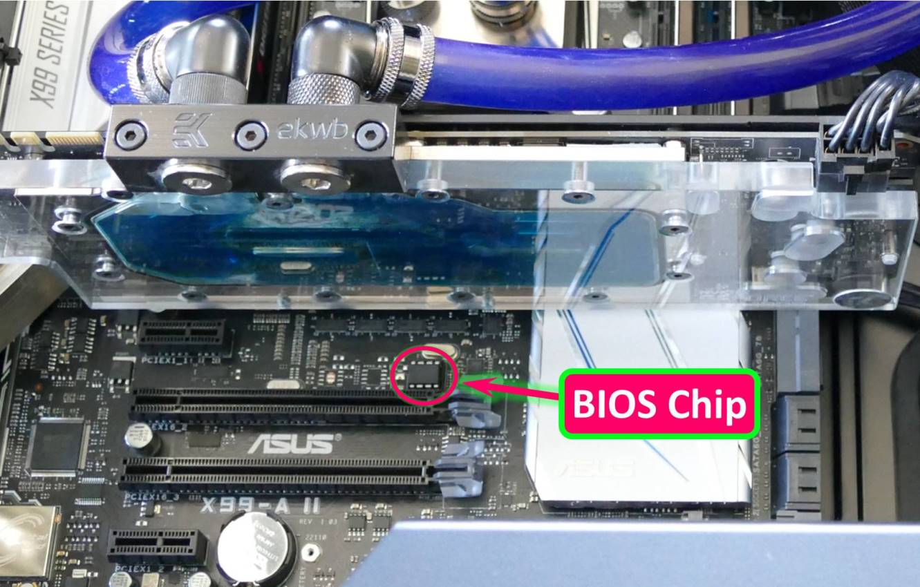
The BIOS firmware is stored on a serial flash chip on the motherboard. Fortunately the chip is socketed so no soldering is required. Otherwise, if the chip is soldered there may be a SPI header on the motherboard. Please see my previous tutorial for SPI programming and desoldering instructions.
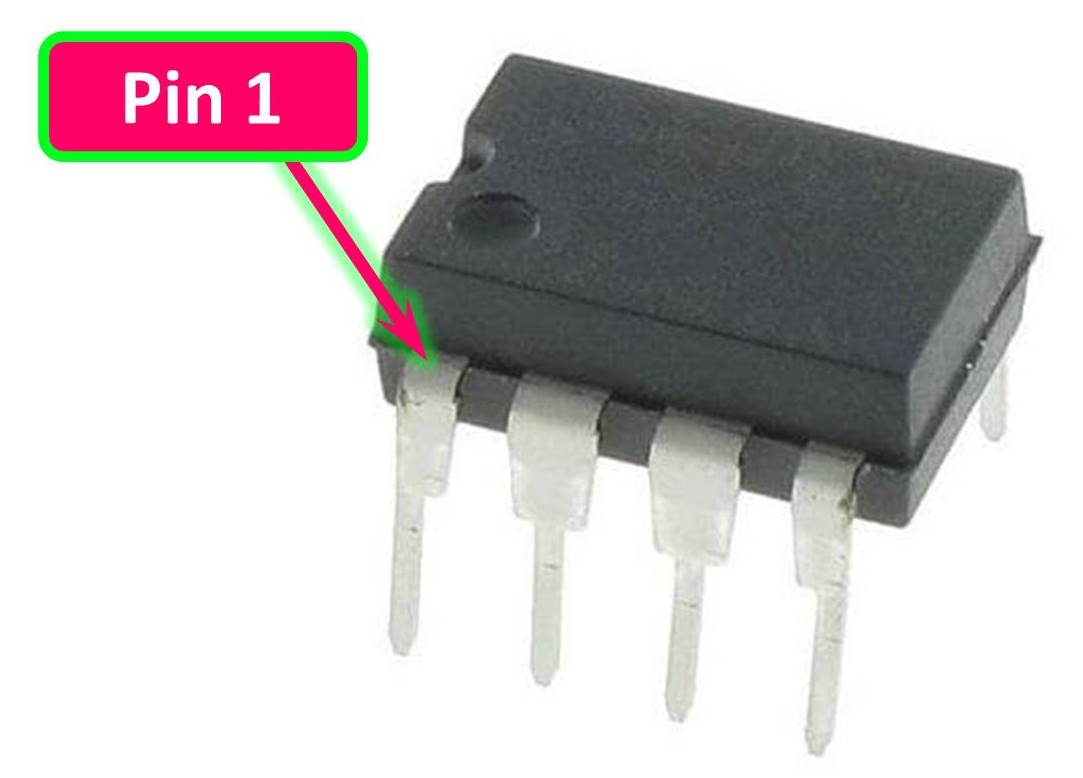
Before removing the chip make sure the computer is unplugged and that you note the pin 1 orientation which is designated by a little notch on one end of the chip and/or a recessed circle.
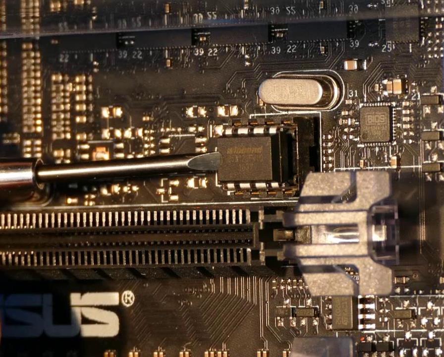
A small screwdriver works well for removing a socketed chip. The blade goes between the chip and the socket. Avoid trying to pry the chip up because the screw driver could scratch the traces on the board. A safer approach is to twist the screwdriver blade. Take turns lifting the chips from opposite sides and only lift a little at a time. If you lift one end of the chip too high it can bend the pins.
 Note: an alternative to a corrupt firmware could be dirty contacts between the BIOS chip and the socket. Cleaning and reseating the BIOS chip is another possible fix.
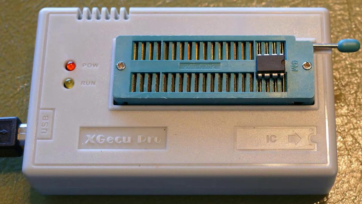
In my previous BIOS repair tutorial, I used a Raspberry Pi as an EPROM programmer. This time I’ll use a TL866 II Plus which is a very popular, inexpensive USB programmer. Of course, a Raspberry Pi would work too. The chip is a Winbond W25Q128FV which is 3 V 128 Mb serial flash memory. The chip is placed in the programmer with the notched end aligned appropriately. The lever locks it in place.
The programming software that comes with the programmer works well. Click the select IC button and then I type W25Q128FV and choose the first 8 pin DIP package.
Your chip will likely be a different brand/model. Please confirm you specify the correct chip.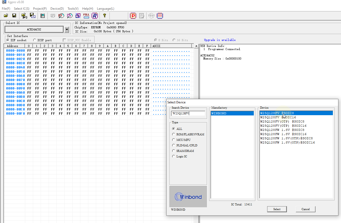
Click Device Read – Read. The BIOS firmware on the chip should load into the buffer. Click File – Save to store the original BIOS to disk. Please make sure you keep a backup copy of the original BIOS just in case something goes wrong.
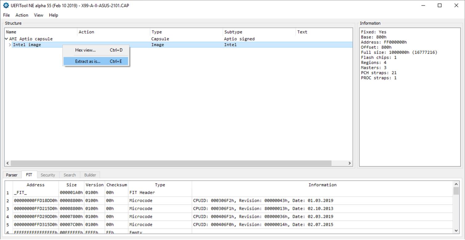
A couple of open source tools are required to work with the UEFI files. Both tools are available on the LongSoft GitHub page. The first one’s called UEFITool. It’s a UEFI firmware image viewer and editor. The second tool is FD44 editor. This utility is specifically designed to edit ASUS BIOS files, but there are editors for other brands. Next download the latest BIOS firmware from the manufacturer’s motherboard driver page. Since I’m using an ASUS X99 motherboard, I’ll download the latest BIOS from the ASUS website. Unlike my previous tutorial, the downloaded BIOS file is a capsule and needs some work before it can be programmed to the flash chip. Run UEFI tool. Click File – Open Image File. Select the new BIOS capsule and click open. Click the arrow to expand the AMI capsule. This shows the Intel image. Right click on the image and select Extract as is. Then save it to disk with a name to designate that it is the new BIOS bin file.
This is the actual firmware that will be uploaded to the chip, but not yet. There’s one more modification necessary. Run the FD44 editor. Click Open from BIOS image file. Select the original BIOS (the one read from the computer.) If you get the message “Data format can’t be detected” then you will need to confirm the data format. If GbE version is present than just leave the default data format which should have MAC address storage set to “GbE region and system UUID”.
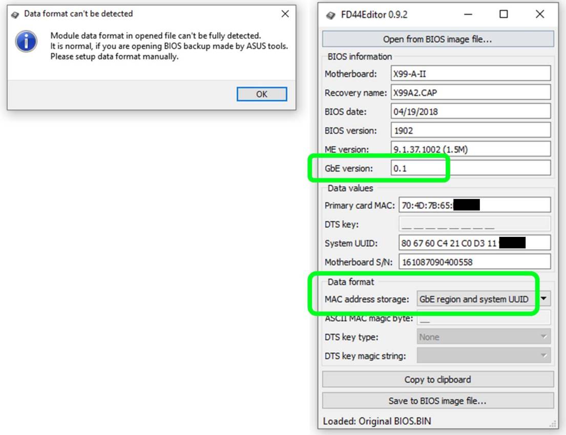
Otherwise if the GbE version is missing then set “ASCII string and system UUID”. You can set any value for ASCII MAC magic byte, but most boards use values from 20 to 2F. Select “None” as DTS key type. If you prefer to select “Long” DTS key type then, use “Default” as DTS Magic string. Some boards will provide the DTS key on a yellow sticker.
Unlike legacy BIOS, UEFI stores the MAC address, the System UUID and the motherboard serial number. This information needs to be transferred to the new firmware before uploading. Copy the results from the original BIOS to the clipboard, and paste them into a text editor such as Notepad.
If you don’t have the original firmware, you might be able to use a fake MAC address. You can’t just make them up. They have to be in the correct format. There are free online tools to generate fake MAC addresses such as this one. However, I have not tried this approach and there is a good chance it won’t work. Therefore, I strongly recommend you use your original MAC address. Often the MAC address is on a sticker on your computer. You might also be able to retrieve the address from your router logs. If you’re using a different editor, I found my MAC address in the first 6 bytes of the GBE region of the hex file and I found the other numbers are in the padding region. I don’t know much about the System UUID. I assume all computers are supposed to have unique ones. On some boards the System UUID contains the DTS key. The motherboard serial number is usually on a sticker on the motherboard, but I think it does need to be exactly 15 digits so you may need to pad it. The MAC address, System UUID and motherboard serial number are usually located close together in the firmware. You can usually find one of the above using a hex editor. Once you locate one number the others are usually within a few lines.
Click open again but this time select the new BIOS file. Ignore any warnings. The MAC address field is just a placeholder and the UUID and serial number will be missing. Copy the motherboard serial number from notepad and paste it into the appropriate field. Next copy the System UUID. If the MAC address is appended to the system UUID then just copy the first 20 digits. Finally copy the MAC address. If you have a different brand motherboard and are using a different editor there could be additional required fields such as model number, service tag, product key, etc. Click Save to Bios Image File and overwrite the new BIOS bin file. Now the bin file is ready to be programmed.
 If you need help finding an editor or are unsure which fields are necessary, I recommend you post a question to the BIOS-mods forum. Also the Win-Raid forum has an excellent BIOS modding section.
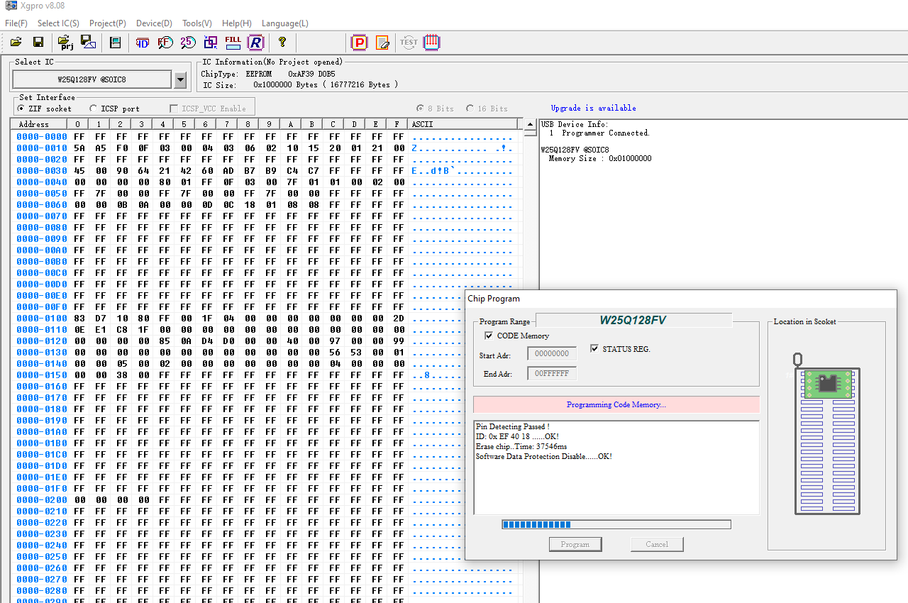
Run the TL866 programming software again and ensure the correct Winbond chip is still selected. Click open and select the New Bios bin file. Leave the default file load options and click OK. Then click Device program and click program. The programming software should erase the chip, program the firmware and verify the chip.
Carefully replace the programmed chip back into the socket in the motherboard. Please make sure the pin 1 notch on the chip is in its prior orientation. Also make sure the chip is firmly seated in the socket. The computer should now boot and display the new BIOS version. The BIOS fields can be verified in Windows using a command prompt and the wmic command:
Display MAC address:
wmic nic get macaddress
Display System UUID. Please note that the raw byte order of the system UUID will be different because Microsoft uses a format called pretty print but all the hex values should match:
wmic csproduct get uuid
Display motherboard serial number:
wmic baseboard get serialnumber