
This tutorial demonstrates how to add Internet access to an nRF52840 board running CircuitPython by using an ESP32 as a WiFi coprocessor. Also a real time clock will be set up an initialized using the correct Internet time and zone returned from a free online API. The DisplayIO library introduced in my last tutorial will be explored in more depth including fonts, shapes and tiles. Bluetooth low energy will be used to afford remote control via a mobile phone.
This is my 4th CircuitPython tutorial. The first one demonstrated getting started with the Adafruit Feather nRF52840 Express and BLE. The 2nd one showed how to flash the Nordic nRF52840 dongle using OpenOCD on a Raspberry Pi and create BLE applications. The 3rd one featured LCD displays and color graphic displays.
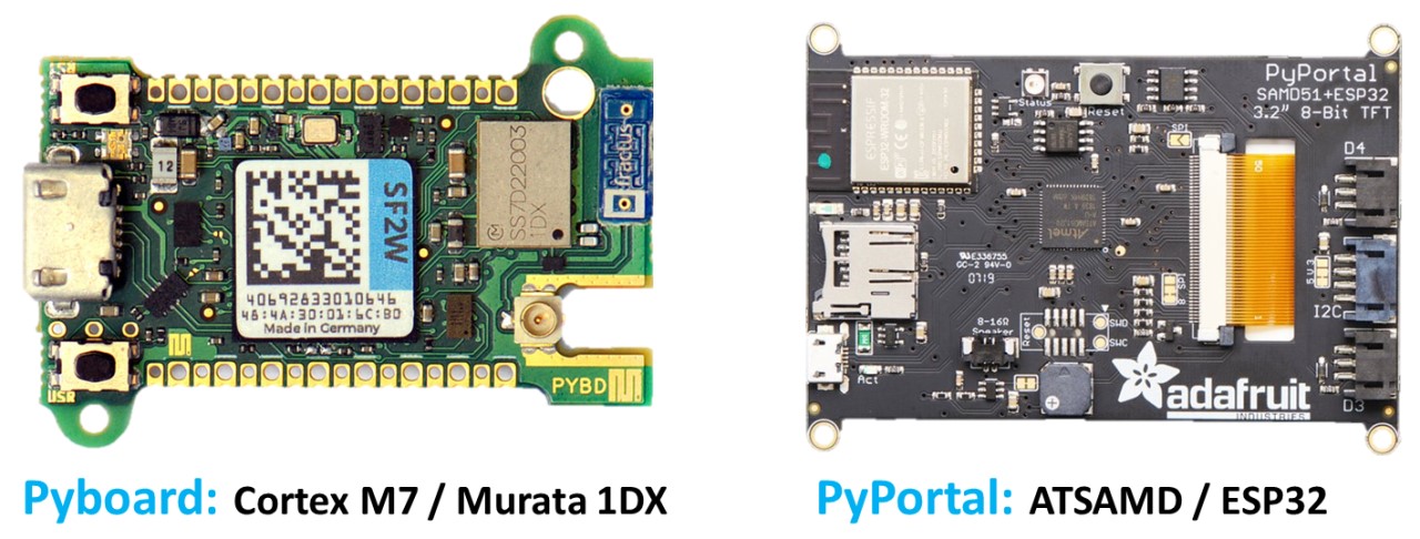
One question you might have is why use an ESP32 as a co-processor? Both the MicroPython Pyboard D and CircuitPython PyPortal have chosen the co-processor approach. The Pyboard D runs a Cortex M7 processor with a separate Murata 1DX module for WiFi. The PyPortal runs an ATSAMD processor with a separate ESP32 for WiFi.
The ESP32 is a powerful board that can run MicroPython by itself, and for many simple projects, this is a valid approach as I’ve demonstrated in my 6 MicroPython tutorials. However, the ESP32 can be a bit sluggish due to its underlying RTOS. There are substantial performance gains by decoupling the WiFi operations from the MicroPython VM. Also CircuitPython will not run on the ESP32 and Adafruit does not plan on adding support. Adafruit may add CircuitPython support for the ESP32-S2 which has built-in native USB.
Since the Pyportal uses an ESP32, Adafruit provides an ESP32 firmware and a tutorial on how to use it. However, the instructions are bit outdated. For example, ESP8266 support has been dropped along with the AT commands. Still, their site contains a download page with the most recent firmware. I have also cached a link to the firmware used in the video.
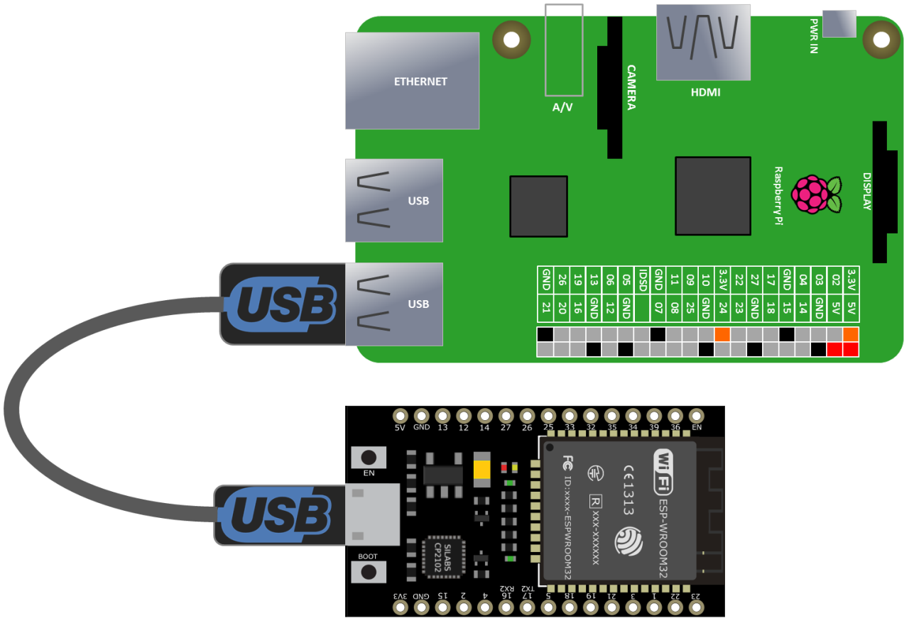
A Raspberry Pi running the latest version of Raspbian can be used to program the ESP32 firmware. A micro USB cable connects the ESP32 to the Pi. It provides power and a serial connection.
A free utility called ESPTool can be used to program the ESP32 with the CircuitPython WiFi firmware. It can be installed using pip.
sudo pip3 install esptool
If you don’t know your ESP32 port, you can use dmesg to identify it.
dmesg | grep ttyUSB
The ESPTool flashid command can be used to test the connection between the Pi and the ESP32. The port parameter is used to specify the USB Port.
esptool.py --port /dev/ttyUSB0 flash_id
If the above command works the ESP32 should be detected. It’s recommended to wipe the ESP32 prior to installing a new firmware. Instead of flash_id use the command erase_flash.
esptool.py --port /dev/ttyUSB0 erase_flash
You should get the message “Chip erase completed successfully.” To write the firmware use the command write_flash. The baud rate should be 115,200. The starting address is 0. The firmware filename is specified.
esptool.py --port /dev/ttyUSB0 --baud 115200 write_flash 0 NINA_W102-1.3.0.bin
A serial console can can be used to test that the ESP32 is working. You can use any serial console. A good free program is MiniCom which can be installed using apt-get.
sudo apt-get install minicom
After the install completes run minicom specifying the port and baud.
minicom -D /dev/ttyUSB0 -b 115200
Once connected, press the reset button on the ESP32. The console should show the boot sequence which means it’s working. The ESP32 can now be unplugged from the Raspberry Pi.
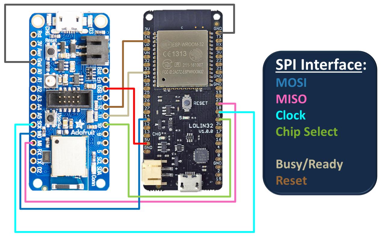
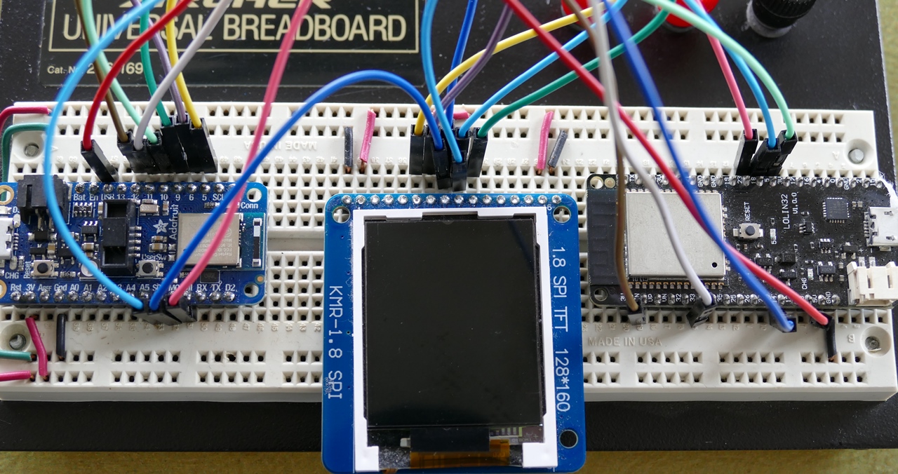
A Feather nRF52840 Express will run CircuitPython and an older Wemos Lolin ESP32 will act as the co-processor. However, any generic ESP32 will work and they can now be purchased for under $5 on eBay. The communication protocol is SPI which uses 4 lines: MOSI, MISI, clock and chip select. Two additional lines will be used to indicate busy/ready and to enable reset. A ground on the nRF52840 is connected to a ground on the ESP32. The MI (MISO) pin on the nRF52840 is connected to GPIO 23. MO (MOSI) is connected to GPIO 14. SCK (serial clock) is connected to GPIO 18. GPIO 10 is connected to GPIO 5 for chip select. GPIO 11 is connected to GPIO 33 for Busy/Ready. GPIO 12 is connected to EN (Enable). This allows for resets. The nRF52840 USB pin is connected to 5 V on the ESP32. This provides 5 V power to the ESP32 from the USB bus.
Here’s a simple program to test the WiFi co-processor. The adafruit_esp32spi library comes with the CircuitPython bundle. An ESP_SPIcontrol is instantiated and passed the SPI bus and necessary GPIO pins. A wifimanager is instantiated and passed the esp, a secrets dict containing WiFi credentials and None for an option status LED. The wifi.get returns the current time in Tokyo. The json method parses the response. The WiFi manager does all the heavy lifting transparently. It connects to WiFI network, sends the request and returns the response.
import board
from digitalio import DigitalInOut
from adafruit_esp32spi import adafruit_esp32spi
from adafruit_esp32spi import adafruit_esp32spi_wifimanager
from secrets import secrets

spi = board.SPI()
esp32_cs = DigitalInOut(board.D10)
esp32_ready = DigitalInOut(board.D11)
esp32_reset = DigitalInOut(board.D12)

esp = adafruit_esp32spi.ESP_SPIcontrol(spi, esp32_cs, esp32_ready, esp32_reset)
wifi = adafruit_esp32spi_wifimanager.ESPSPI_WiFiManager(esp, secrets, None)

print(wifi.get('http://worldtimeapi.org/api/timezone/Asia/Tokyo').json())
It’s recommended not to store your SSID and password in your main program for security reasons. Therefore, a separate secrets file is imported. A dictionary called secrets has keys for ssid and password. You would enter the SSID and password for your router. If you’re using version control such as GitHub, make sure you add this file to the ignore list so it doesn’t get publicly posted.
# This file is where you keep secret settings, passwords, and tokens!
# If you put them in the code you risk committing that info or sharing it
secrets = {
    'ssid': 'your SSID',
    'password': 'your password',
}
The next demo is a BLE controlled world clock that will return time and weather data for cities around the world and show them on an ST7355 color LCD display. The ST7355 can share the SPI pins (MOSI, MISO & clock) with the ESP32. However, it will need 3 GPIO pins for reset, A0 and chip select which will be GPIO 5, 6 & 9 respectively. The 3.3 V display can be powered by the feather.
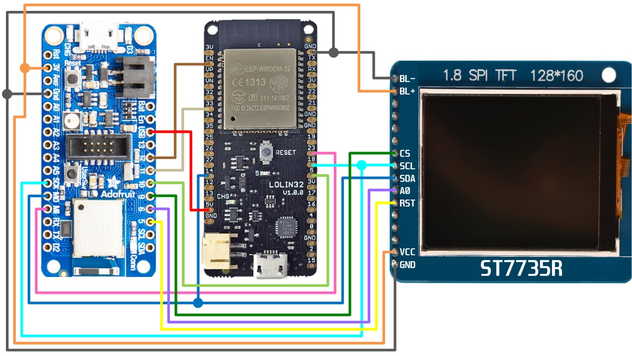
Here’s a shot of everything wired up on the breadboard.
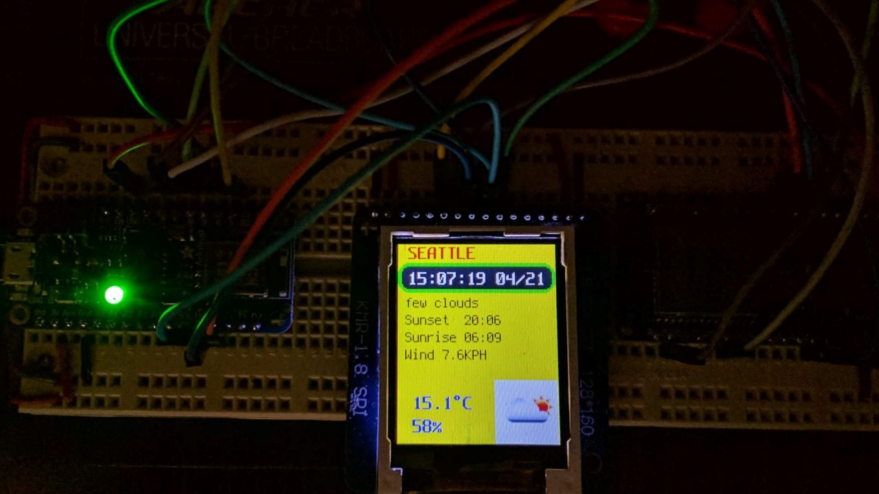
Adafruit provides a DisplayIO compatible library for the ST7735. The World Time API used above will return the current time and timezone. A real time clock can be initialize with the returned data. The clock will keep time and can be checked using the localtime method. The FCC Weather API will return weather conditions. The FCC API returns a hyperlink to a weather icon. Unfortunately, the icon is in PNG format which isn’t supported yet by CircuitPython. I tried to write a PNG decoder, but gave up when I realized that CircuitPython does not support Zlib compression on the nRF52840 yet. So instead my weather library returns a frame index based on the returned icon. A tile grid is set to the specified frame which displays the corresponding weather condition icon on the LCD.

The DisplayIO library allows you to use custom fonts. Currently only BDF is supported. BDF is a very archaic bitmap font format, but since it came out in the 80’s there are a lot of free fonts available. Tecate offers a free BDF collection. A free cross platform font-editor called FontForge can be used to create and edit BDF fonts. The DisplayIO custom font handling is a bit sluggish. You can improve performance by removing unused characters from the BDF font. Preloading the fonts with the load_glyphs method will also expedite your code.
A BLE app such as Nordic nRF Connect (Android & iOS) or Adafruit Bluefruit LE Connect (Android & iOS) can be used to send a city name to the program’s BLE UART server. Here’s a shot of the city time and weather data displayed on the ST7735 LCD.
Downloads:
Weather clock code and resources (rev. 12-16-2020)
My next tutorial demonstrates how to build a BLE client remote control to operate a BLE server peripheral hosting a solenoid and a light detected.