In this tutorial I’ll repair a network controllable rack mount power conditioner.
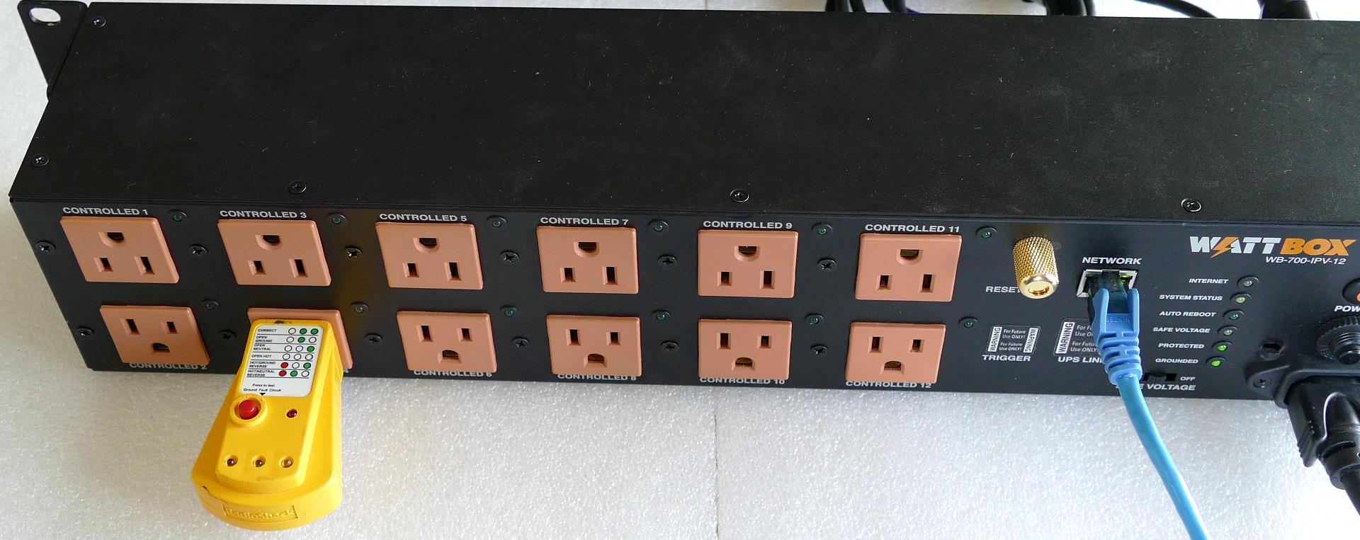
The Wattbox WB-700-IPV-12 is a power conditioner that I rescued from e-waste along with an optional WB-600-FP face plate display. It has 12 AC outlets. In addition to providing clean power, each outlet can be remotely controlled through a web interface. It can also ping connected devices and power cycle them if they fail to reply.
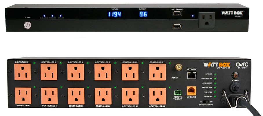
The Wattbox products are geared toward smart homes and small businesses (presumably without IT staff) but are not sold to the public. You have to be an authorized professional integrator according to their website. I tracked down an authorized integrator and their website shows a price of over $1000 US for the power conditioner and the optional face plate. I’m not a big fan of products aimed exclusively at integrators because it’s hard to find reviews, they are often overpriced, you can’t install them yourself, and you may have a limited choice of available integrators.
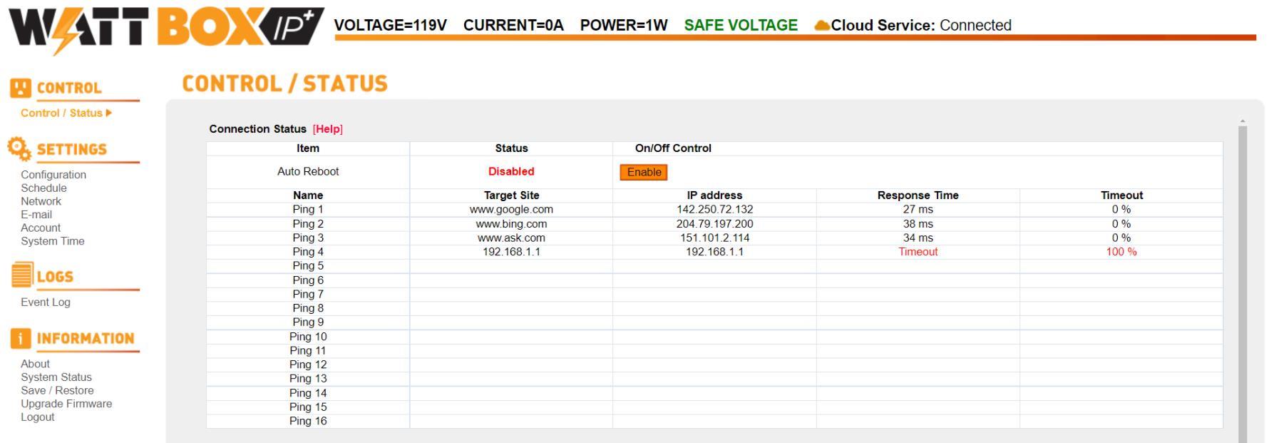
The web interface has a connection status section that shows the status of specified network equipment by pinging them.
Below is a visual representation of the power conditioner with corresponding green LED indicators (showing all on). Unfortunately, the green LED’s on the actual power conditioner are still all off. Apparently, the software isn’t smart enough to know that the unit isn’t working. There really should be some type of feedback if the relays do not fire especially since this device is designed for remote management. Under the image is the status and control section which allows you to manually toggle each outlet on or off. Again, the status on every outlet shows on despite them being off.
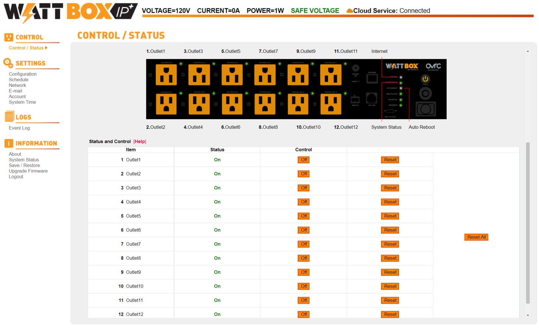
In addition to the lights next to all plugs being off, I checked each outlet with receptacle tester to ensure there was no power.
 Warning: the power conditioner uses potentially lethal voltages. Please exercise the appropriate caution and if you are unsure check with an electrician or electrical engineer because you could get hurt or burn down your home.
The Wattbox power conditioner contains several circuit boards. All but one of the electrolytic capacitors in the device are Capxon brand which has a sketchy reputation among several of the online electrical engineering forums where they are sometimes referred to as Crapzon.
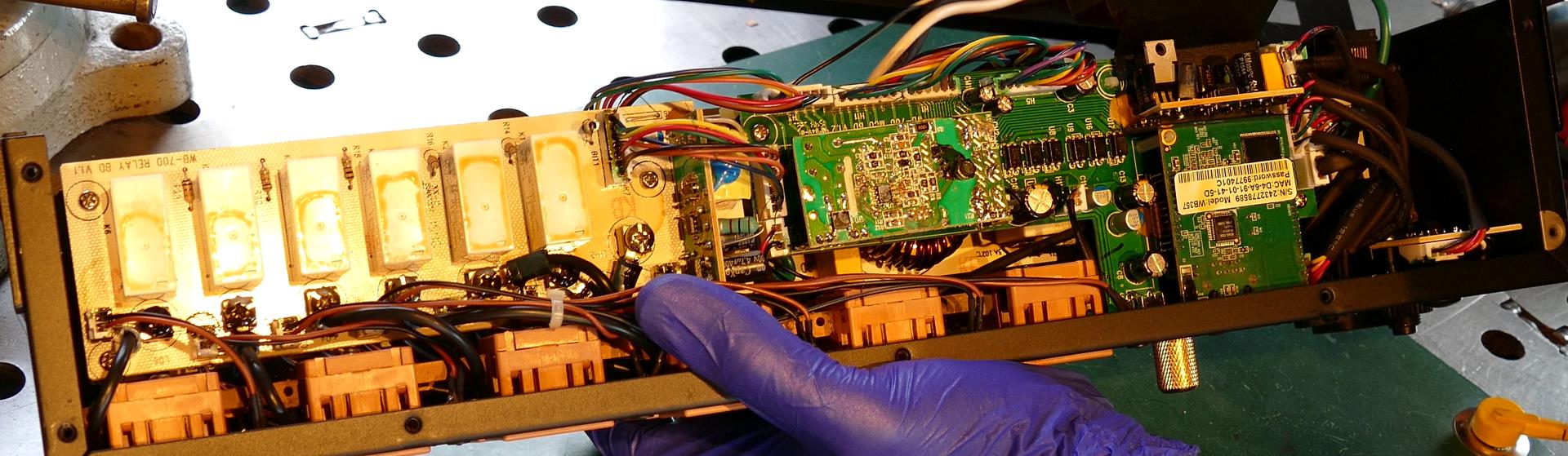
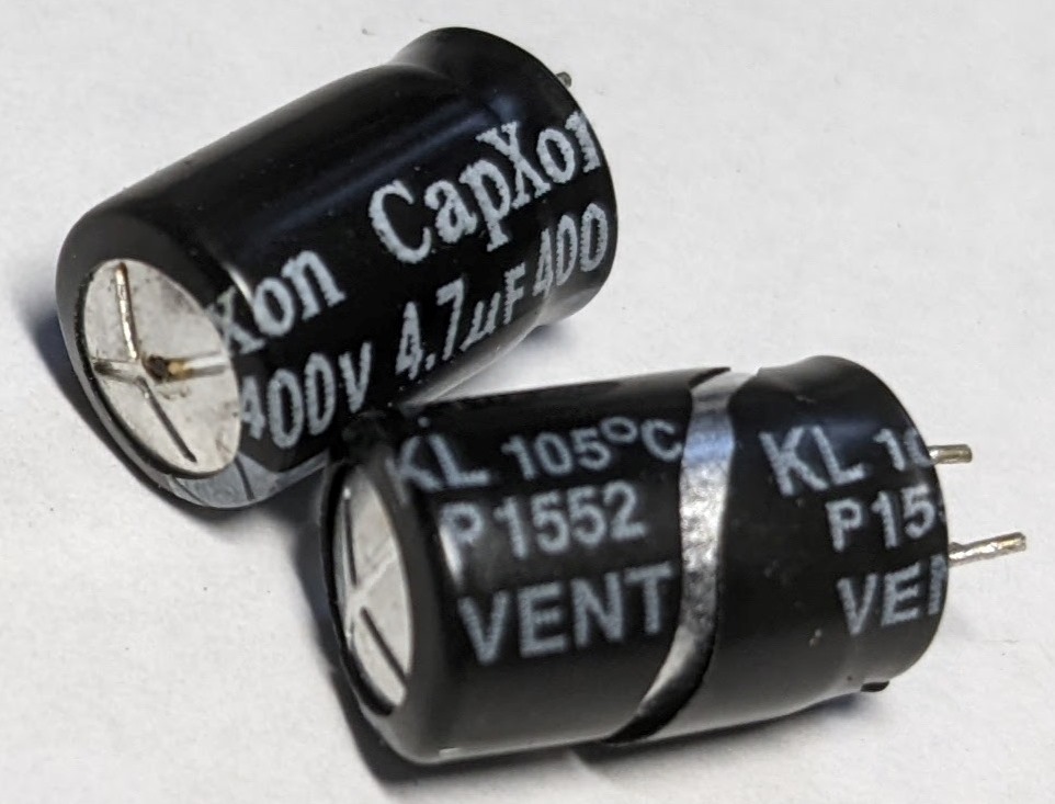
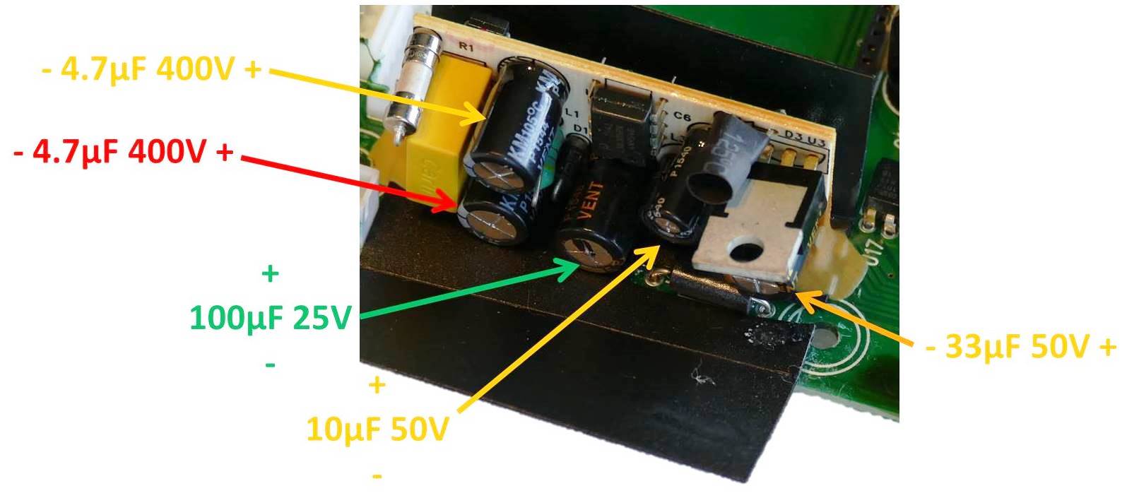
There are 2 relay boards with a total of 12 relays corresponding to each of the 12 power outlets. The lower relay board is part of the main power conditioning board. The top one is a separate board. Each board contains 6 relays and has a separate 12 V power supply daughter board. There are 4 CapXon electrolytic capacitors for each power supply. The solid polymer caps tested OK. The other two 400 V 4.7 μF caps were very bad.
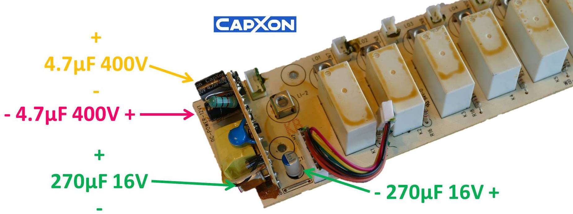
One of the 400 V caps was so bloated that the plastic casing actually cracked in half. The cracked capacitor was unreadable and the other one had an ESR of over 100 Ω. If the relay coils aren’t getting power that would explain why the 12 outlets aren’t working.
The back of the relay board is all surface mount components. There are 6 transistor circuits to fire each relay.
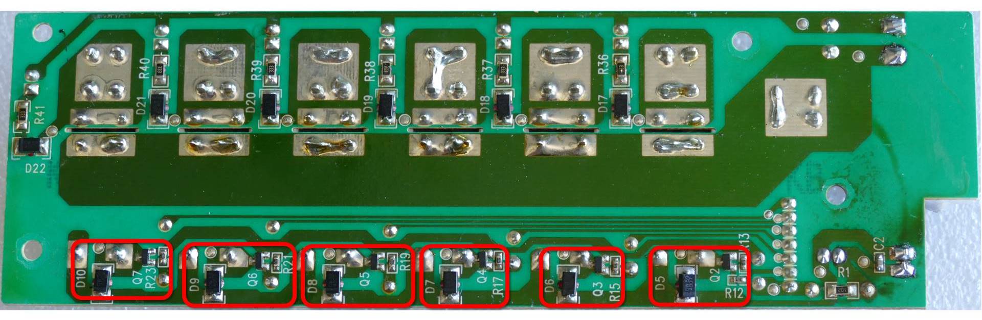
The control signal from the microprocessor flows through a 1K ohm resistor on the other side of the board to throttle the current. A 20K Ω pull-down resistor ensures the transistor base doesn’t float. When the microcontroller pulls the control signal high the transistor allows 12 V current to flow across the coil and activate the relay. A snubber diode dissipates any voltage spikes when the coil is de-energized.
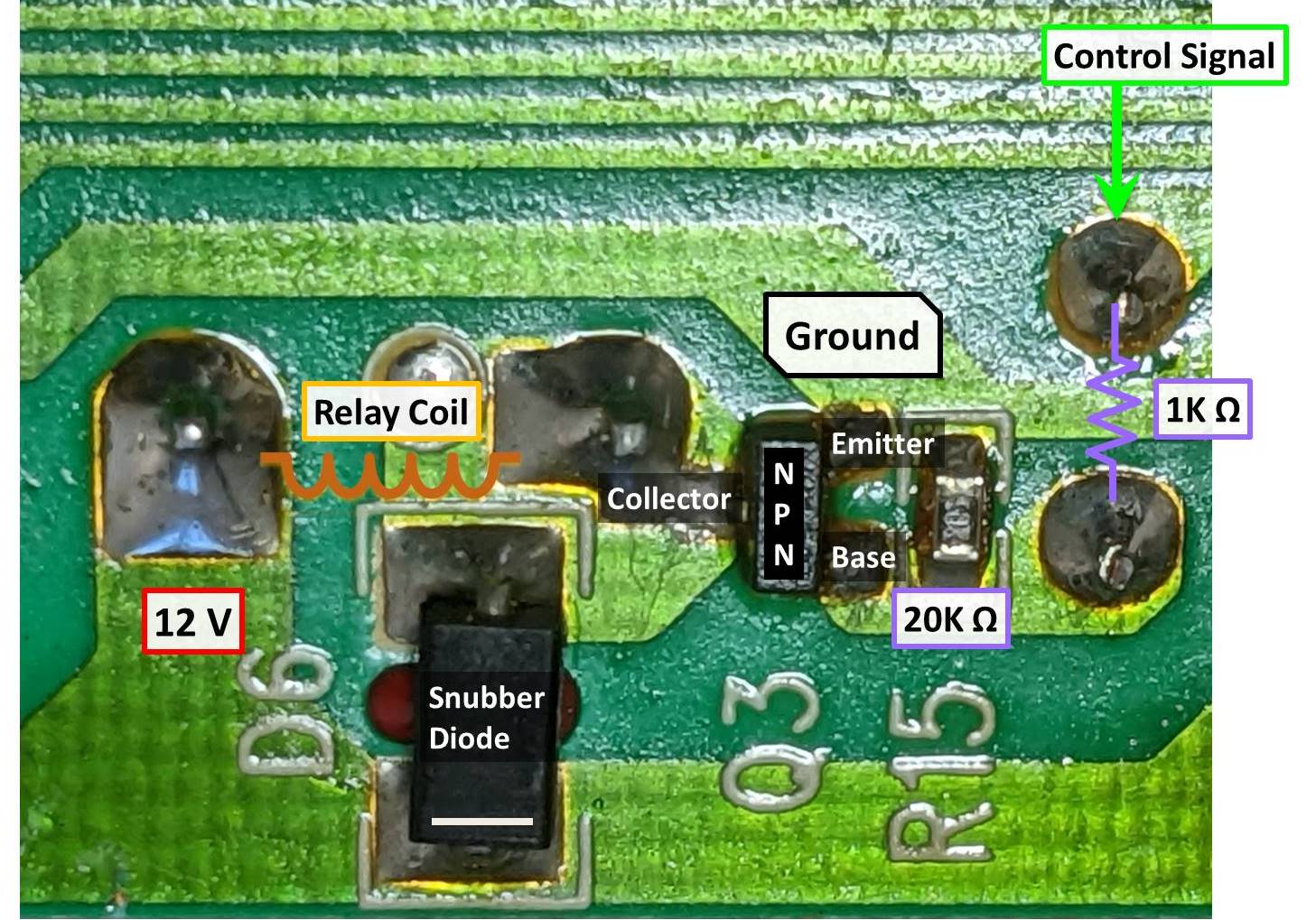
If any of these components were shorted, it could prevent the relays from functioning. However, I tested all 6 circuits and they’re all OK.
The main logic board is the brains of the power conditioner. There are 8 Capxon electrolytic capacitors. Half of the caps tested good and the other four had somewhat high ESR. Regardless, I replaced them all.
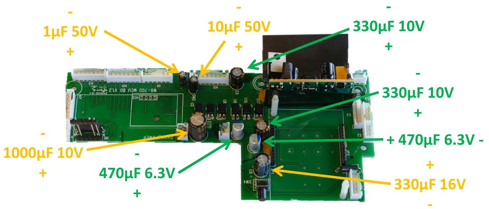
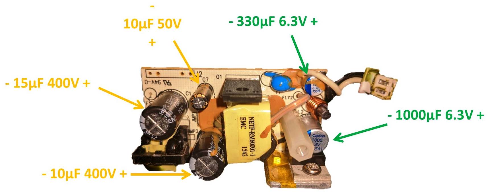
The main logic board has 2 power supply daughter boards. The first one has 5 Capxon electrolytic capacitors. Only 1 cap tested good. One of the 400 V caps was very bad with an ESR of 75 Ω. The other 3 caps had relatively high ESR.
The other power supply board daughter board on the main logic board has 5 Capxon electrolytic capacitors. Two caps were good and the other 3 had somewhat high ESR.
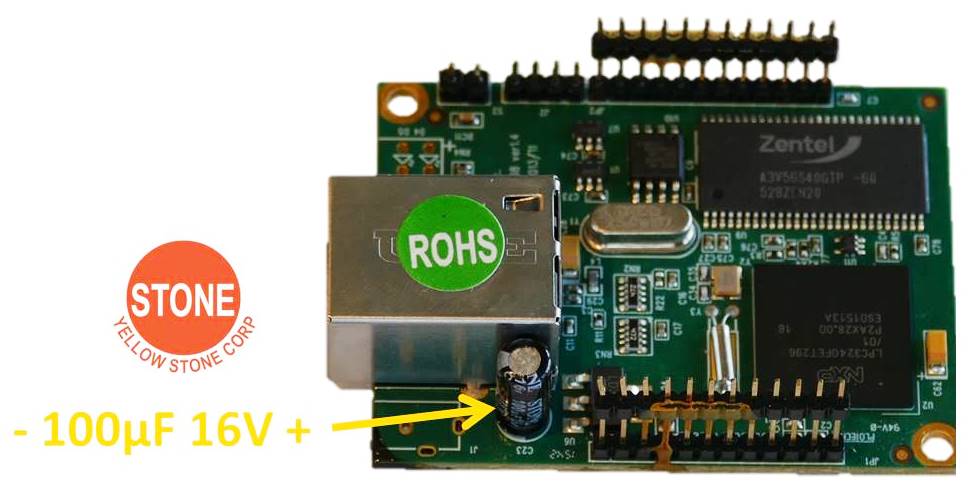
The main logic board has a third daughter board that provides Ethernet access. This board contained the only capacitor that wasn’t a Capxon brand. Instead it was a Stone brand. Regardless the ESR value was a bit high so I replaced it.
I ended up replacing all the capacitors in the power conditioner. I selected all Japanese low ESR replacements. Here is a summary.
| Value | Qty. | Dimensions | Replacement |
|---|---|---|---|
| 1 μF 50 V | 1 | 5 mm x 12 mm | Rubycon 50YXF1MEFC5X11 |
| 10 μF 50 V | 3 | 5 mm x 12 mm | Rubycon 50ZL10MEFC5X7 |
| 10 μF 400 V | 1 | 10 mm x 16 mm | Nichicon UVY2G100MPD |
| 15 μF 400 V | 1 | 10 mm x 16 mm | United Chemi-Con EKXL451ELL150MJ20S |
| 33 μF 50 V | 1 | 8 mm x 12 mm | Rubycon 63PZE33M8X9 |
| 100 μF 16 V | 1 | 5 mm x 11.5 mm | Rubycon 16ZLH100MEFC5X11 |
| 100 μF 25 V | 1 | 8 mm x 12 mm | Nichicon UPV1E101MGD1TD |
| 330 μF 16 V | 1 | 8 mm x 12.5 mm | Nichicon UHD1C331MPD |
| 4.7 μF 400 V | 6 | 8 mm x 12.5 mm | Nichicon UVC2G4R7MPD1TD |
| 1000 μF 10 V | 1 | 10 mm x 16 mm | Panasonic EEU-FM1A102 |
| 100 μF 16 V | 1 | 6 mm x 11 mm | Nichicon PLF1C101MDL4 |
| 270 μF 16 V | 4 | 6 mm x 11 mm | United Chemi-Con APSG160ELL271MF08J |
| 330 μF 6.3 V | 1 | 6 mm x 5.5 mm | Nichicon RS80J331MDN1JT |
| 470 μF 6.3 V | 2 | 6 mm x 11 mm | United Chemi-Con APSE6R3ELL471MF08S |
| 1000 μF 6.3 V | 1 | 8 mm x 12 mm | Nichicon RNU0J102MDN1 |
Unfortunately, after replacing all the capacitors the power conditioner relays are still not firing and the outlets are dead. It’s likely the failed caps on the relay power supply boards caused additional damage. I replaced all the caps on the top of the board except the blue Y1 safety cap because it is not actually connected to anything.
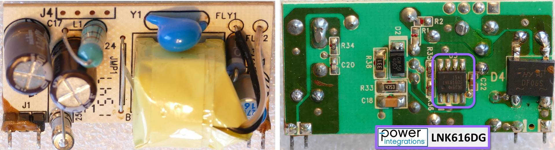
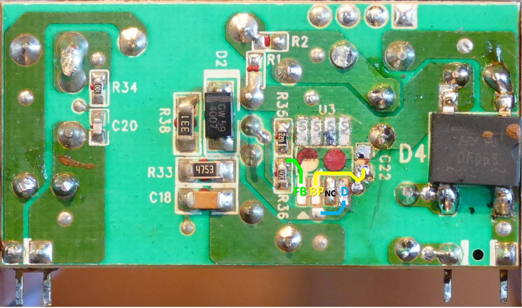
There’s 162 VDC on the output side of the power board’s bridge rectifier so it is getting power and the rectifier is working. However, there is no power on the low voltage output side of the board even when I pull the power supply out of circuit. The small AC to DC power supply is controlled by a LNK616 IC which is designed for low power constant voltage/constant current designs such as a charger or power adapter. I tested the fuse and it’s OK.
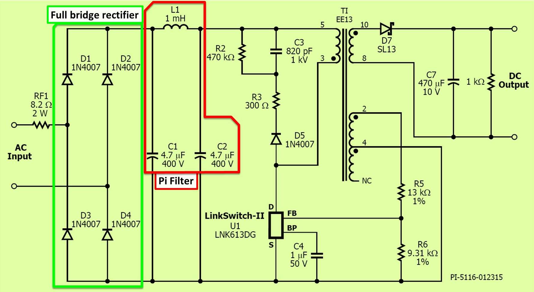
I found this sample schematic in the datasheet. It’s for a LNK613 which is the same except for a lower power rating. AC input power is rectified by diodes D1 through D4 which forms a full bridge rectifier. The rectified DC is filtered by the bulk storage capacitors C1 and C2. These are the 2 failed 400 V caps. The 2 caps are combined with inductor L1 to form a pi (π) filter, which attenuates EMI noise.
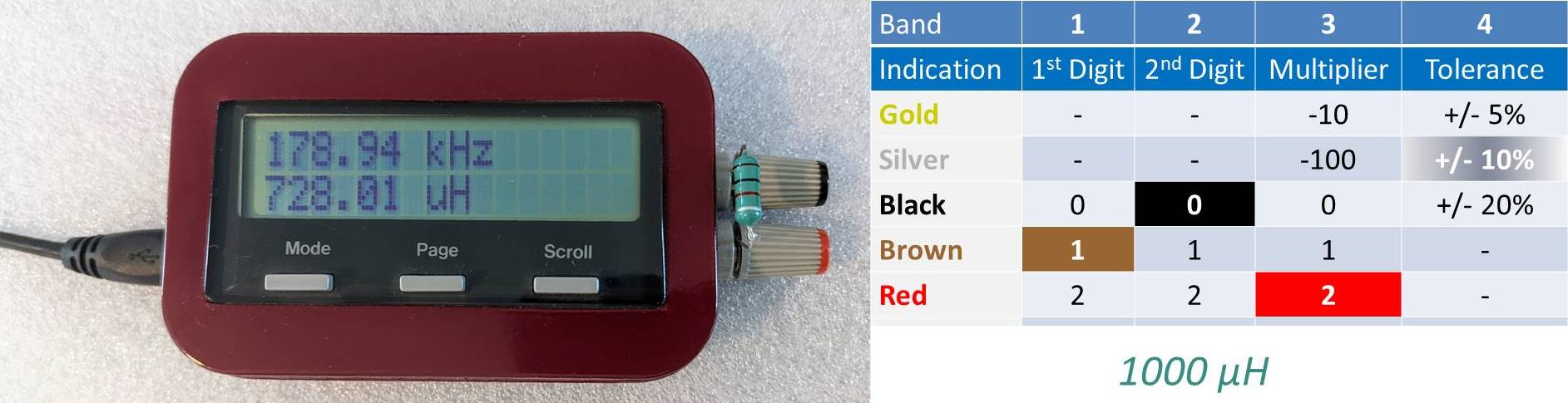
I pulled the inductor to check it with my home-made inductance meter. The 1000 μH inductor has an actual value of about 728 μH. That’s out of spec. The silver band on the inductor indicates a 10% tolerance and it’s off by more than 27%. I’ll replace the inductor, but I don’t think the value discrepancy would account for the complete failure of the power converter.
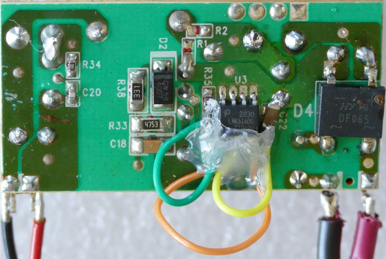
I tested the surface mount resistors, diodes and small caps on the power supply daughter board and didn’t find any issues. I had to remove a few components to test them, and it was very difficult because they were glued down. The only part left is the LNK616 chip. I found online posts suggesting that these chips can easily be damaged, so I went ahead and replaced it. I ended up destroying some of the pads when I removed the chip due to the glue.
However, I was able to bypass the damage with some 26 AWG Teflon wire. Teflon wire is great for soldering because the insulation does not melt or shrivel up. I secured the wire with hot glue.
I tested the repaired power supply out of circuit by connecting two 22 Ω (5 watt) resistors in series (44 Ω) and the supply produced 11.3 V.
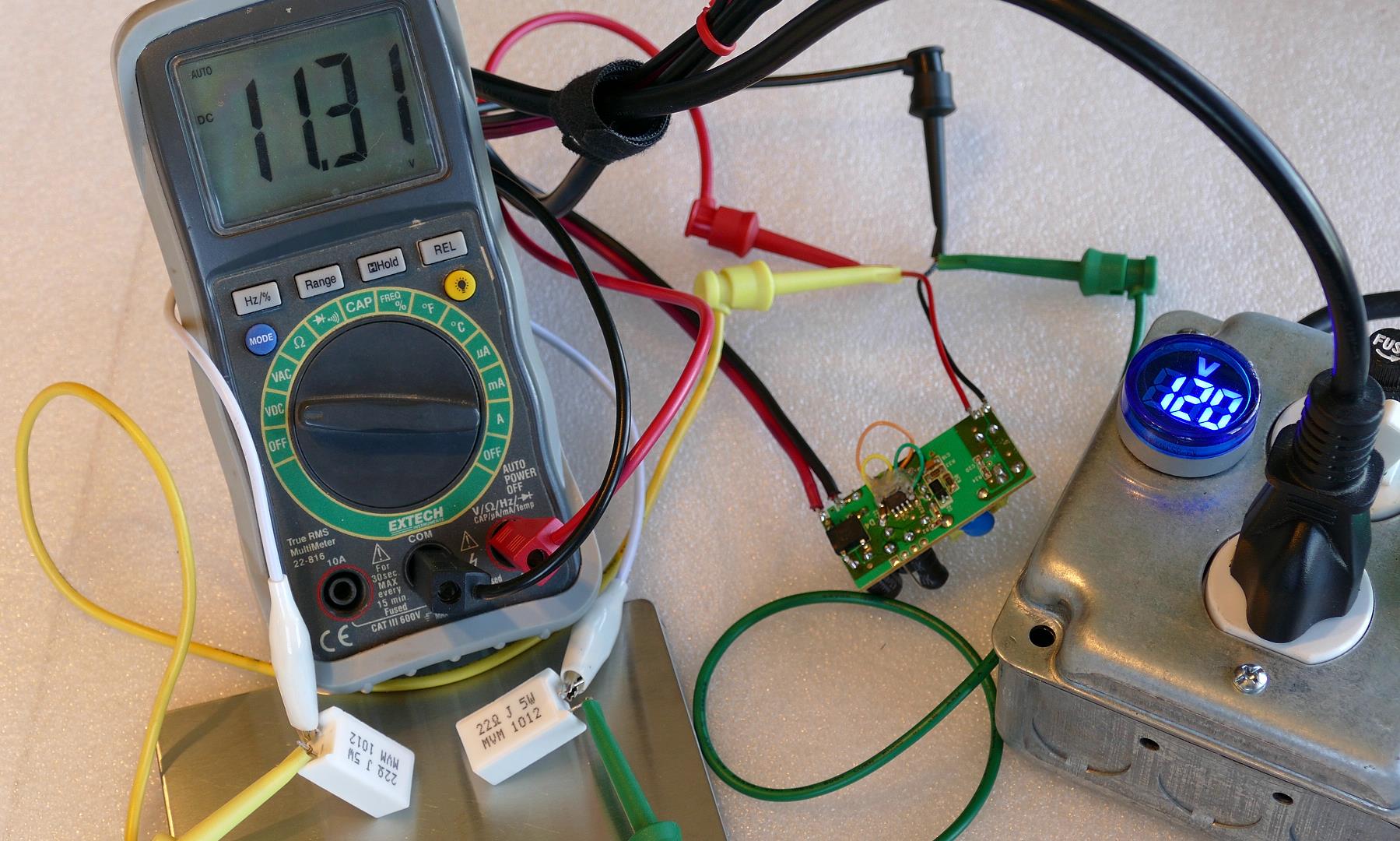
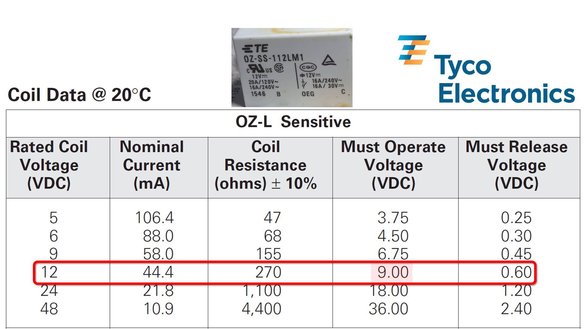
The board should be supplying over 250 mA which is close to what the six 44.4 mA relays coils will be drawing if they are all on simultaneously. The voltage is a little low but should be adequate to power the 12 V relay coils. According to the relay datasheet the coils must operate at a minimum voltage of 9 V.
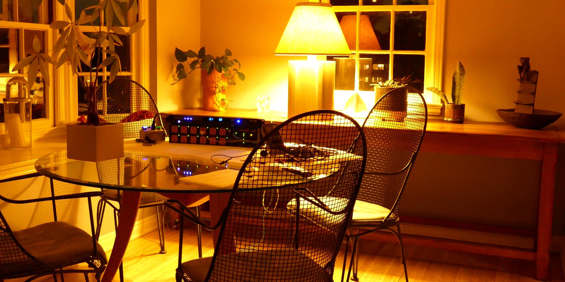
I put everything back together after fixing 1 solder bridge and it works. Basically, poor quality electrolytic capacitors failed and damaged the power supply IC’s for the relay boards. Here’s a shot of the power conditioner with all the outlet LED indicators lit up green and controlling a table lamp.