This tutorial demonstrates the repair of an Adafruit nRF52840 Feather Express board with a defective LiPo charge controller.
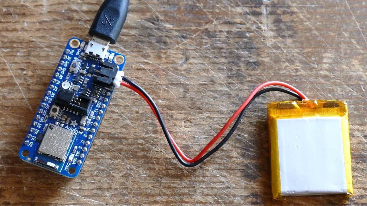
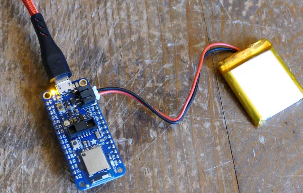
Here’s the defective Feather board connected to a 3.7 V, 500 mAH LiPo battery. Despite being plugged into a 5 V USB, the yellow LED charging indicator is not illuminated. It’s not just a broken LED because I verified the battery is not getting charged with a multimeter.
Let’s start with a visual inspection. Under magnification with the colors inverted there appears to be a possible burn mark on top of a 5 lead SOT23 package. The board also has the distinct smell of burnt semiconductors so this chip is a very likely culprit.
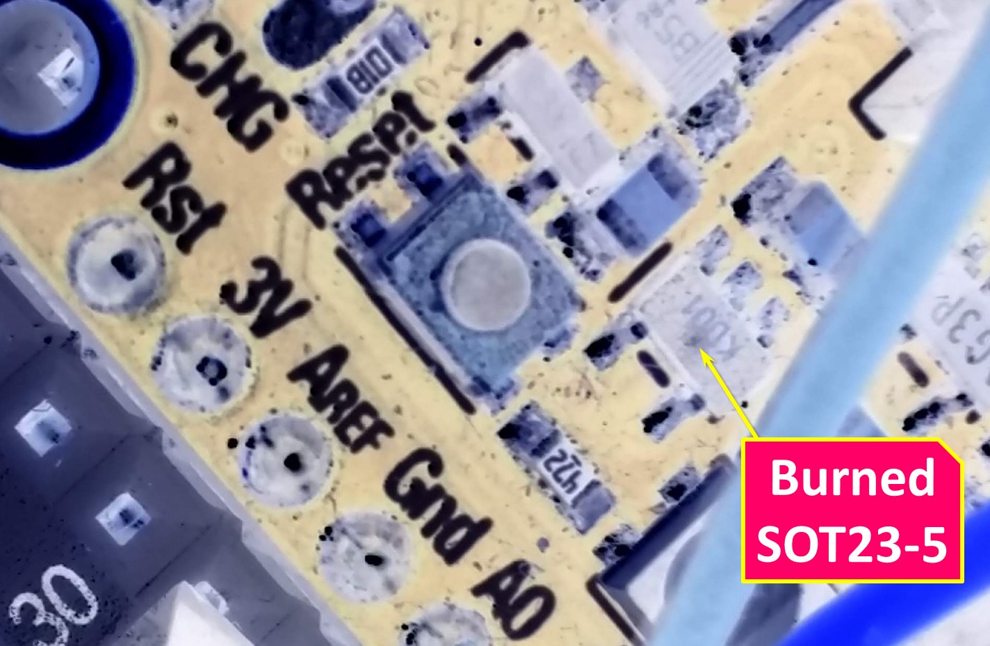
When working with surface mount parts it can be difficult to identify a chip. The SOT23 package is labelled “KDO1” which doesn’t mean anything to me. There are several resources online for identifying chips such as the SMD Codebook. Although it looks like it hasn’t been updated since 2015. Here’s a PDF version. Digikey and S-manuals also have look-ups for SMD markings. I searched online but could not find a match for KDO1. It’s probably a packaging code which I would not be able to decipher without the datasheet.
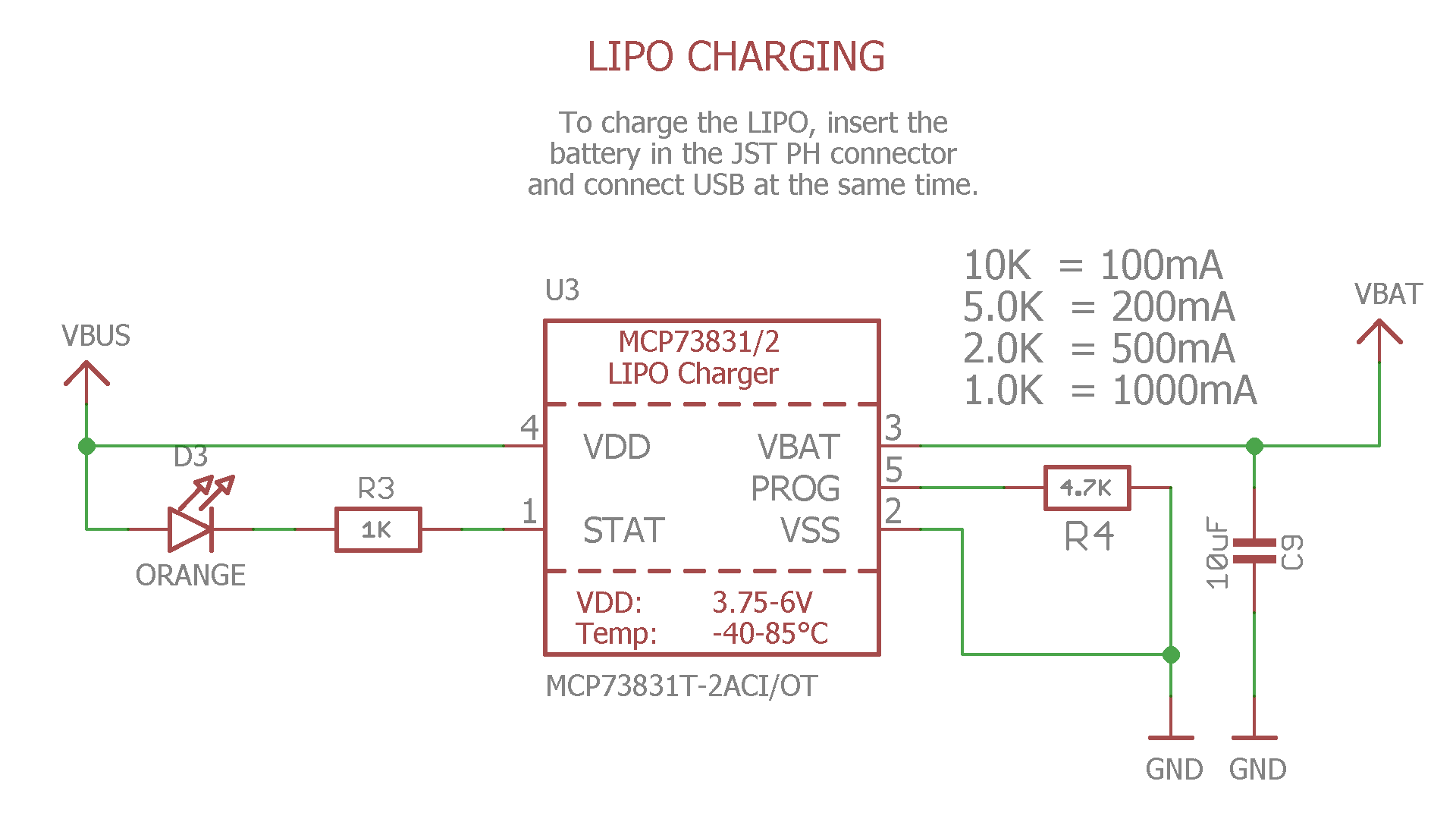
Fortunately, Adafruit provides excellent schematics for all their boards. Here’s the schematic for the nRF52840 Feather. If you’re going to design a schematic, this is a great example! All the different board functions are neatly organized and labelled.
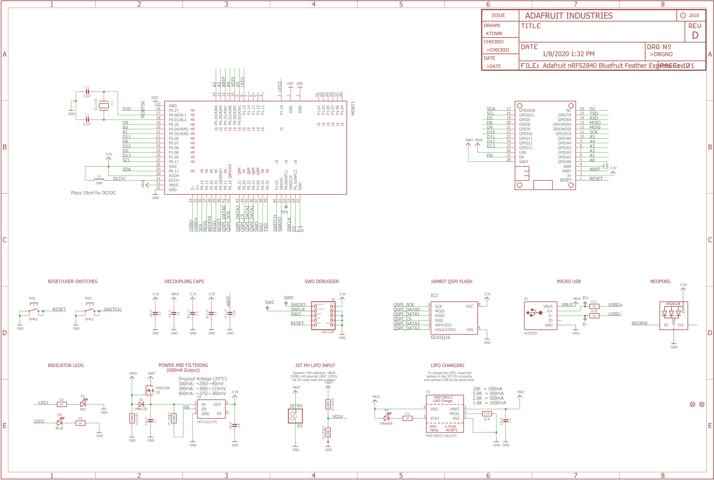
For example, here’s a close-up of the Lipo charging section. The main component is a MCP73831/2 LiPo charger IC. It’s 5 pin which matches the burnt SOT23 chip. Mouser has them in stock for 50 cents so it’s definitely worth fixing. The circuit is very simple. VDD goes to 5 V. VBAT goes to the battery with a 10 uF decoupling cap. VSS goes to ground. The STAT pin drives an LED status indicator in-line with a 1000 ohm resistor. The PROG pin allows you to set the charging current via the R4 resistor. The board uses a 4700 ohm resistor to set the current to 200mA.
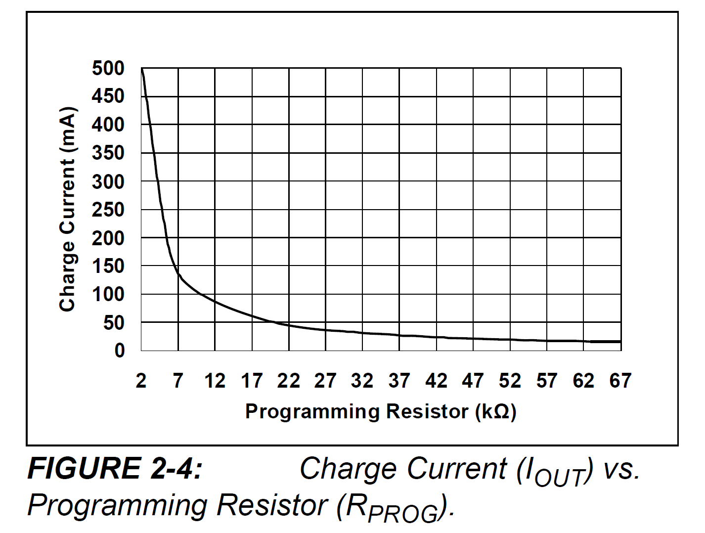
Here’s a chart from the MCP73831/2 datasheet. Raising the value of the programming resistor lowers the charging current. My application for this board does not require fast charging so I’ll try raising the resistor value to 10K ohms to cut the charge current from 200 mA to 100 mA. Hopefully, this will reduce heat and improve longevity.
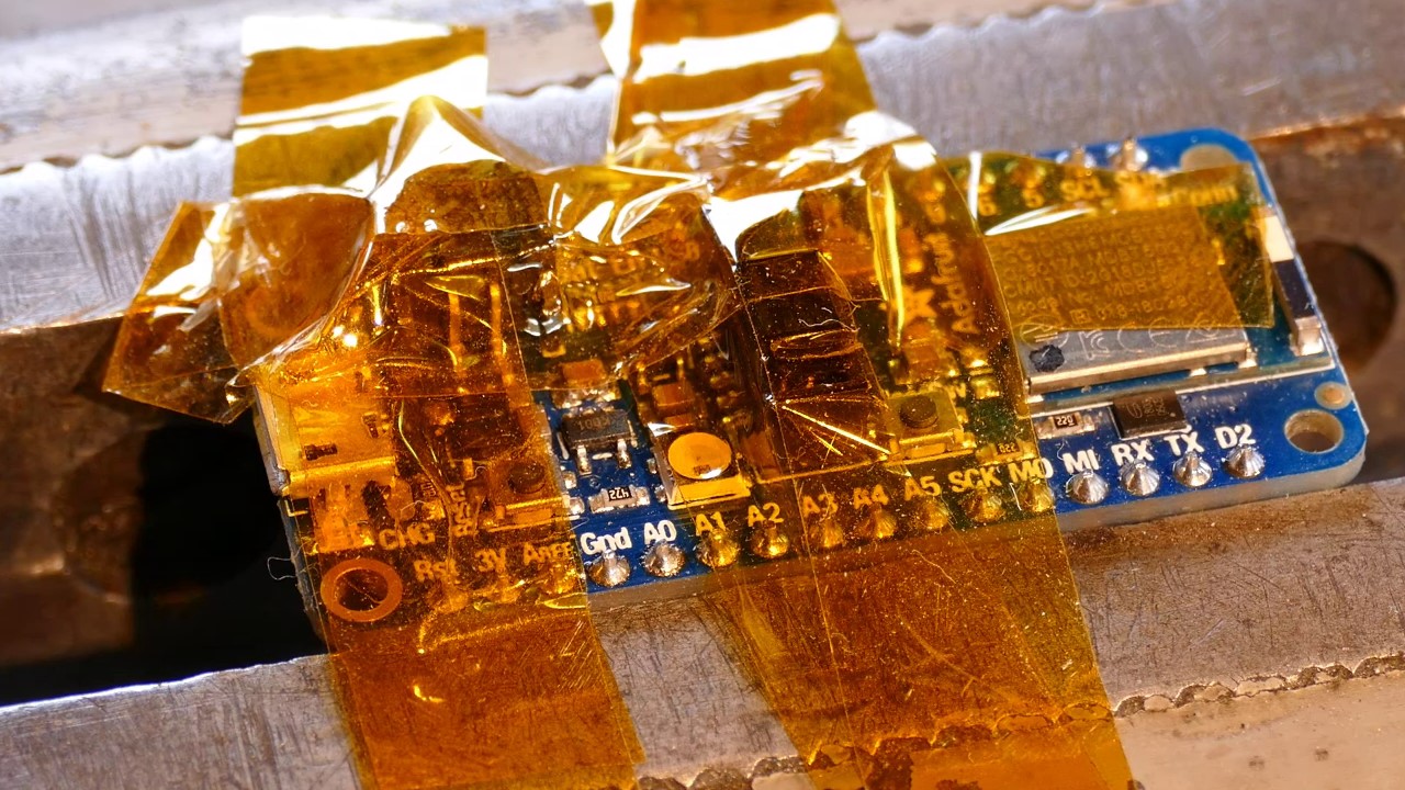
I like to cover the board around the work area with Kapton tape so I don’t melt any of the plastic parts or accidentally remove something. I’ll remove the charge controller chip and the programming resistor using my 858D hot air rework station.
After replacing the MCP73831/2 chip and the programming resistor, the yellow LED charging indicator is illuminated.
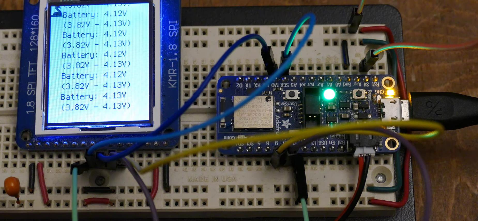
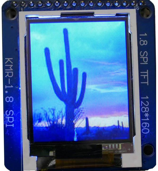
Let’s write a quick CircuitPython program to verify the charger is working. An ST7735 color 128×64 LCD display will provide feedback even if the USB cable is disconnected from the computer. The display uses a SPI interface and can be powered directly from the Feather’s 3.3 V pin even when running on battery.
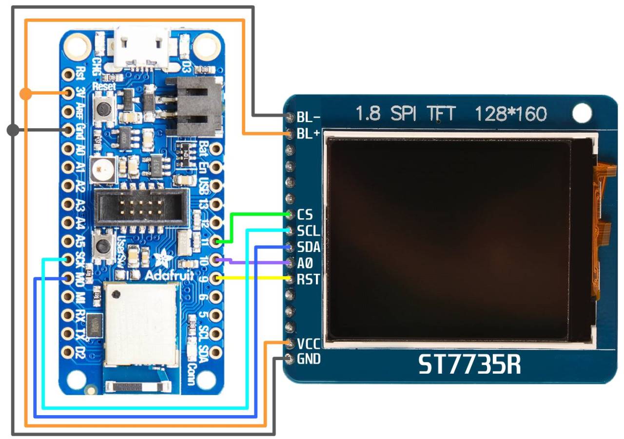
I’m not going to go into detail on connecting the display because I already made a CircuitPython nRF52840 LCD Display tutorial dedicated to the subject. Here’s the wiring schematic.
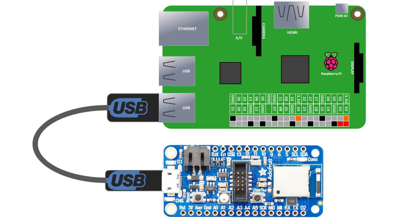
The nRF52840 Feather board is connected to a computer via a micro-USB cable. I’ll use a Raspberry Pi 4. The latest version of Raspbian comes with the Mu editor which is an excellent IDE for writing CircuitPython code.
Here’s the code. The first section after the imports is boiler plate for the LCD display. One cool feature of the DisplayIO library is with just this basic set up, all REPL output will automatically be piped to the LCD display. Afterwards, the Python print statement can be used to show output on the display.
import board
from time import sleep
from analogio import AnalogIn
import displayio
from adafruit_st7735r import ST7735R

spi = board.SPI()
cs = board.D11
dc = board.D10
rst = board.D9
displayio.release_displays()
display_bus = displayio.FourWire(spi, command=dc, chip_select=cs, reset=rst)
display = ST7735R(display_bus, width=128, height=160)

battery = AnalogIn(board.BATTERY)

minV = 1000
maxV = 0

while True:
    v = battery.value * 3.3 / 65535 * 2
    minV = min(v, minV)
    maxV = max(v, maxV)
    print("Battery: {0:.2f}V\n({1:.2f}V - {2:.2f}V)".format(v, minV, maxV))
    sleep(2)
The main loop polls the Feather’s analog battery pin, converts the results to voltage, tracks the minimum & maximum range and outputs the results. The analog pins have 16 bit resolution. Therefore, the battery voltage is represent by a value between zero and 65535. This is converted to voltage by multiplying by the reference voltage of 3.3 V and dividing by the resolution. Looking at the JST PH LiPo input section of the schematic, there’s a voltage divider comprised of two 100K ohm resistors between VBAT and GND.
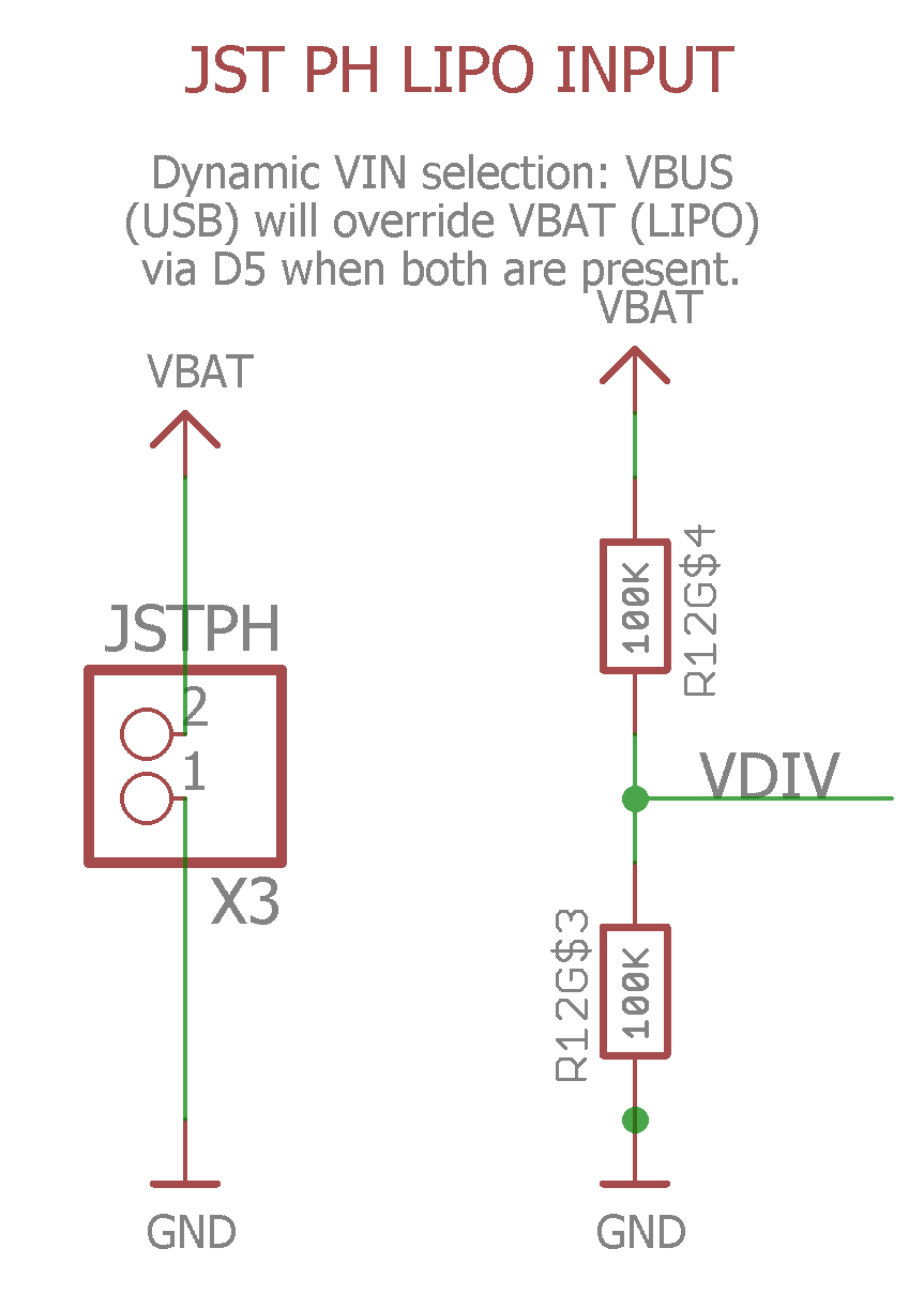
The voltage measured by the board’s analog battery pin is at VDIV. Since the resistors are identical, the measured voltage is equal to 1/2 the actual battery voltage. The voltage is reduced because the LiPo battery voltage typically exceeds the 3.3 V reference voltage which is the maximum that the analog pins on the Feather can tolerate.
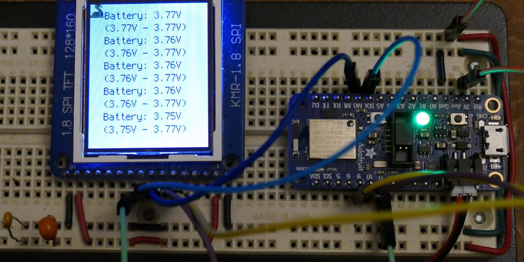
Here’s a breadboard with an ST7735 LCD connected to the Feather which is running off battery. The LiPo voltage is around 3.7 V which is about the nominal voltage. A fully charged LiPo should be closer to 4.2 V.
After about 1 hour of charging the battery is looking good at 4.1 V.