
This CircuitPython tutorial demonstrates how to build a battery powered Bluetooth BLE remote control to operate a BLE peripheral hosting a solenoid and a spectrally selective light detector. Two Adafruit Feather nRF52840 Express boards will be used for the BLE client and server.
This is my 5th CircuitPython tutorial. The first one demonstrated getting started with the Adafruit Feather nRF52840 Express and BLE. The 2nd one showed how to flash the Nordic nRF52840 dongle using OpenOCD on a Raspberry Pi and create BLE applications. The 3rd one featured LCD displays and color graphic displays. The 4th one demonstrated how to add Internet access to an nRF52840 board by using an ESP32 as a WiFi co processor.
Here’s a surveillance camera server that’s located in a locked closet.
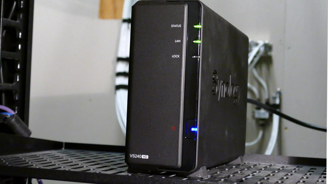
Currently the only way to turn it on is by pressing the illuminated push button on the front of the case. My goal is to build a BLE peripheral that can attach to the front panel so I can turn it on remotely from outside the closet. I also want the peripheral to wirelessly report whether the server is on or off.
There are several ways to determine if a device is powered on such as a non-contact current sensor or measuring voltage on the PCB but I think the least expensive and least likely to void the warranty will be to detect if the blue light on the on/off push button is illuminated.
LED’s are great for emitting light, but they can also be used for detecting light. Many electronic devices can be reversed. For example a motor can be powered by electricity or it can generate electricity, a speaker can also be used as a microphone and an LED will generate current when exposed to light. Additionally, LED’s are spectrally selective. In other words, they can detect specific colors of light.
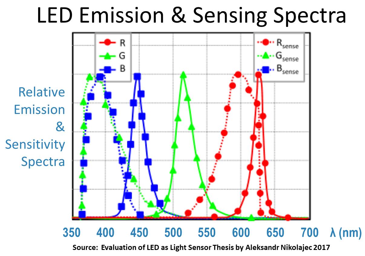
Generally speaking LED’s are most sensitive to light that is lower than their dominant emission wavelength. Therefore, a yellow or red LED may yield the best results for detecting a green LED. Likewise an aqua or green LED could be used to detect blue light. My testing found that a sensing LED with a wavelength 50 nm greater than the emitting LED worked best. If you don’t know the wavelength of the emitting LED and you don’t have an expensive spectrometer, it can easily be found using a diffraction grating such as this slide which cost under a dollar.
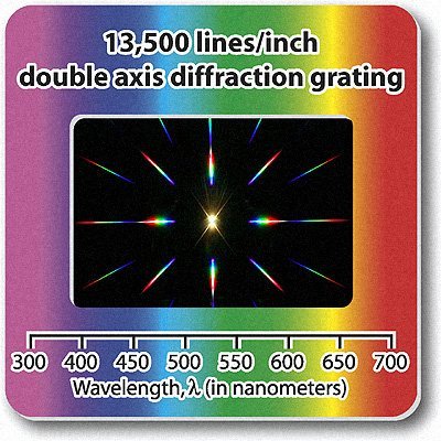
Place a ruler directly in front of the LED to measure. Then position the slide at a known distance of at least 5 feet from the LED. Longer distances tend to give more accurate results. Looking through the slide you’ll see that some of the light gets diffracted.
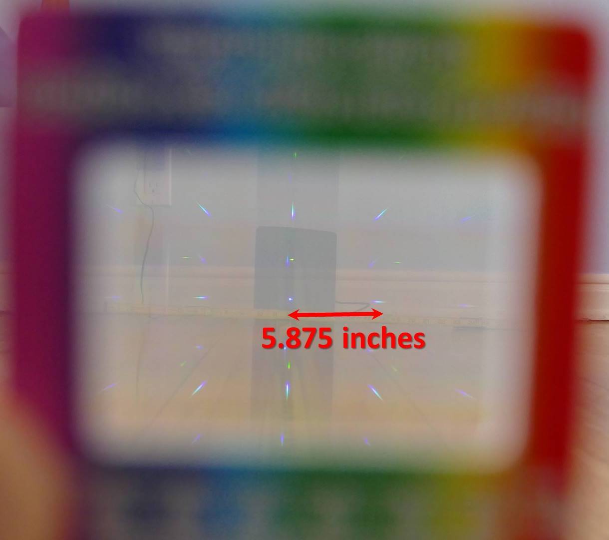
The ruler in front of the LED can be used to measure the distance from the light source to its nearest neighbor either left or right. In this case the value is 5.875 inches. The wavelength represented by λ (lambda) is equal to the following formula where d is the distance between slits in the diffraction grating, y is the distance between the LED and its nearest neighbor and L is the distance from the slide to the LED.
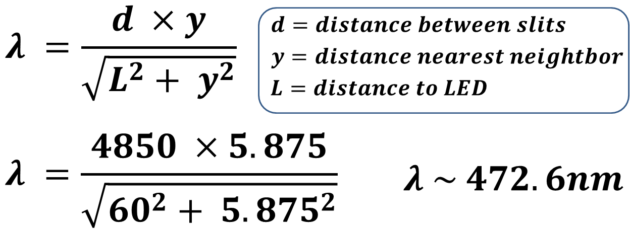
My diffraction grating slide has a value of d equal to 4850 nm. If you don’t know this value it can be determined by solving for d with an LED of a known wavelength. The distance to the nearest neighbor y is 5.875 inches and the distance from the slide is 60 inches. The units cancel out so it doesn’t matter if you prefer metric. Plugging in the numbers gives a wavelength of 472 nm for the blue led on the surveillance server power button. Therefore, an LED 50 nm higher or around 522 nm should work well as a detector. I’ll use a Broadcom high intensity green LED with a wavelength of 525 nm. It has a narrow 15 degree viewing angle and a water clear lens both of which should improve the sensitivity. More information on measuring wavelength is available here.
Wiring the LED to the nRF52840 feather is very straight forward.
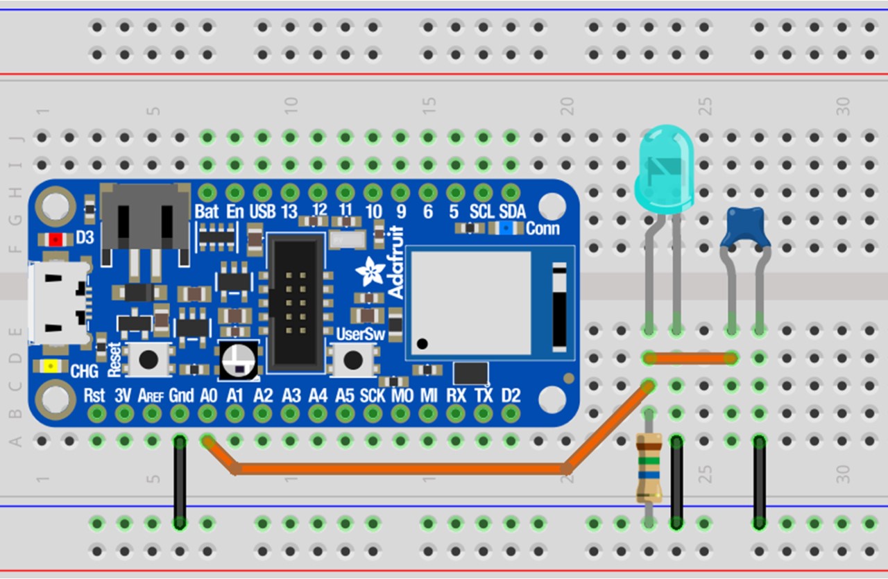
The LED will generate a voltage when it detects light. Therefore, the LED anode is connected to A0 which is 1 of the 6 analog to digital pins on the Feather that can read voltages and convert them to a 16 bit value. The Feather’s ground and the LED cathode are connected to a ground rail on the breadboard. As is this circuit would be very noisy and unreliable. Therefore, a filter is added which is comprised of an 82 nF ceramic capacitor and a very weak 15 MΩ pull-down resistor. Both are placed between the LED anode and ground. That’s all it takes for the detector circuit. The Feather should now be able to read a voltage change on A0 when a bright blue light hits the attached green LED.
A mini 5 V push-pull solenoid will be used to press the button on the front of the surveillance server.
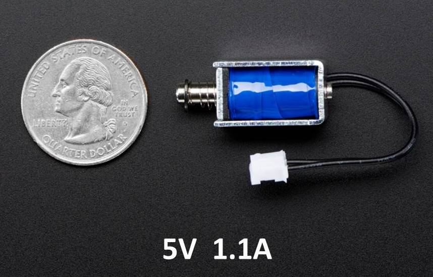
The solenoid is an electromagnet. The metal rod in the center is called an armature. It will be drawn into the solenoid when power is applied to the coil. When power is cut, the spring will return the armature to its starting position. The solenoid draws 1.1 A which is much more than the GPIO pins on the Feather can source or sink. Therefore, a logic level N-channel MOSFET will be used to drive the solenoid.
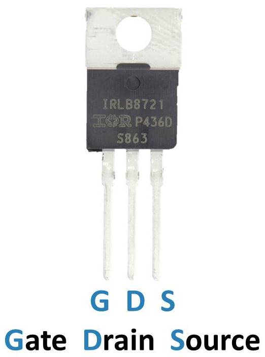
The MOSFET can act like a switch. When voltage is applied to the gate pin it allows current to flow between the drain and the source pins. An IRLB8721 is selected because its gate can be driven at logic level voltages such as the 3.3 V GPIO pins of the nRF52840 Feather. The solenoid and MOSFET are also easy to wire up.
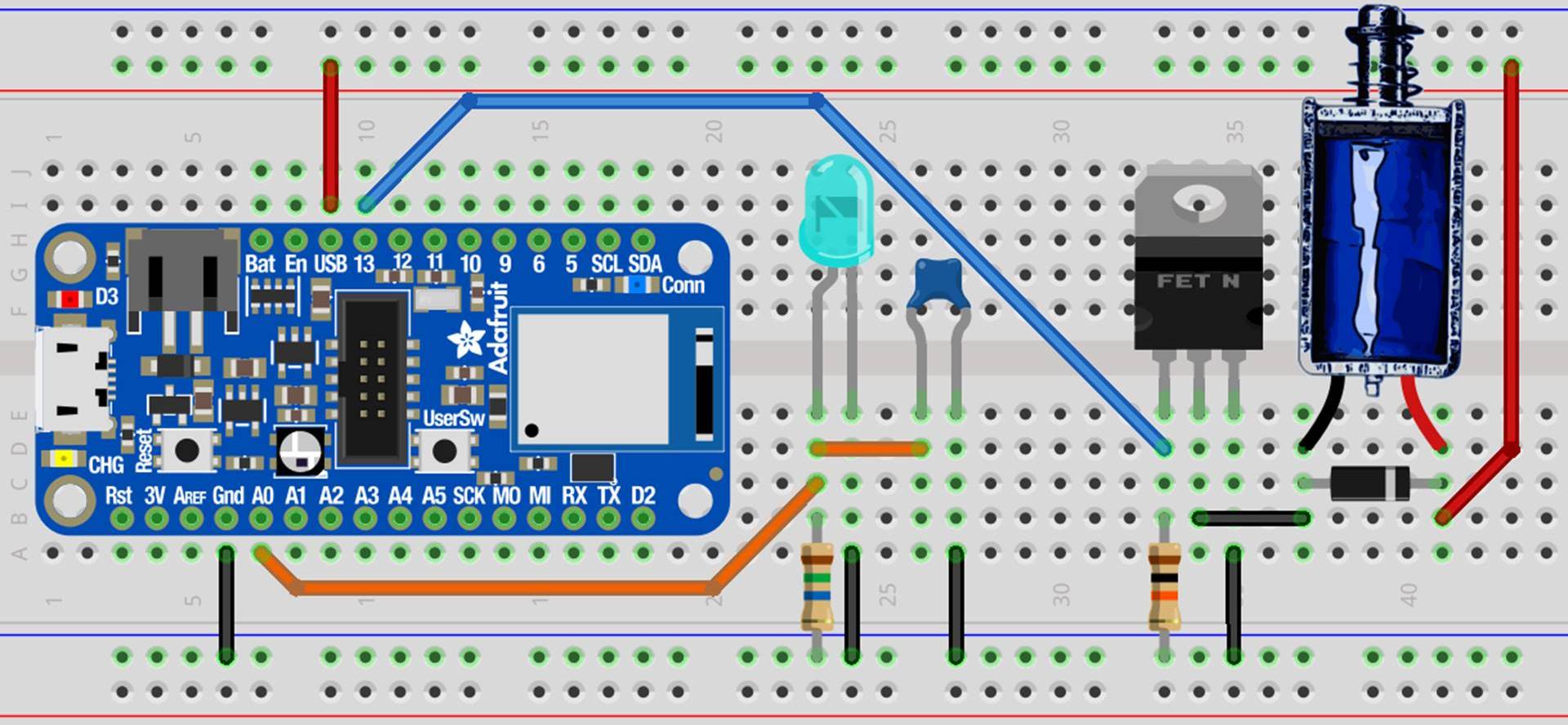
The 5 V USB line on the Feather and one lead from the solenoid are connected to a 5 V rail on the breadboard. The other solenoid lead is connected to the MOSFET drain pin. The source pin is connected to ground. When enough voltage is applied to the gate, it will complete the circuit and the solenoid will activate. The gate is controlled by GPIO 13. An optional 10 KΩ resistor pulls the gate to ground. This mitigates coupling capacitance and ensures the solenoid will not activate if the gate is allowed to float. A 1N4004 snubber diode is placed as close as possible to the solenoid leads with the cathode on the positive side. The diode protects the circuit. When power is cut to the solenoid the electromagnetic field collapses and can generate a substantial flyback voltage which could damage the MOSFET or other components. The snubber diode dissipates this current.
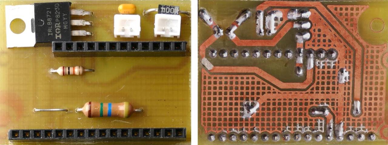
Here’s the breadboard components converted to a small 45.5 mm x 35.5 mm PCB board design using the free version of Autodesk Eagle.
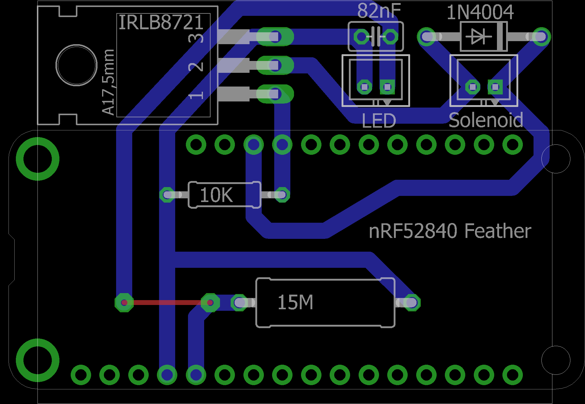
Two female 2.54 mm headers (12 & 16 pin) accommodate the Feather. Two male 2.0 mm JST PH shrouded connectors (2 pin) receive the LED and solenoid. I etched the board myself using a laser printer and muriatic acid. I’ve also posted my etching instructions. If you don’t fell like doing it yourself there are many online services that can prototype a PCB for a very reasonable fee. You could also use a perf board.
The free version of SketchUp was used to design a bracket to hold the PCB to the front of the surveillance server.
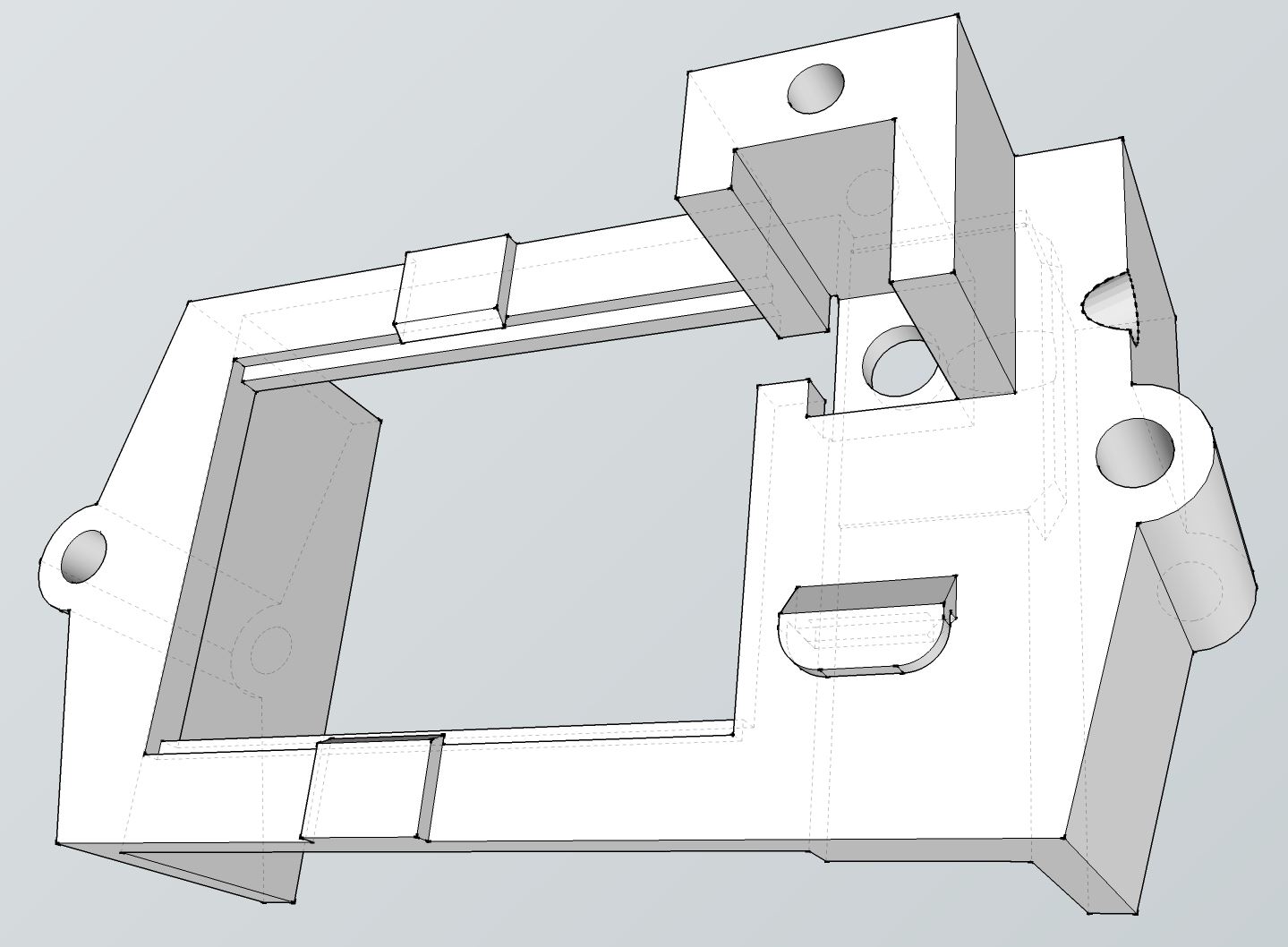
There’s a slot to secure the solenoid over the push button. On the side is a through hole for the LED light detector. The bracket will slide over the front of the server. Threaded rods will mount through the holes on the side and secure it to another bracket in the back. The PCB will snap into the middle section and is restrained by top and bottom clips.
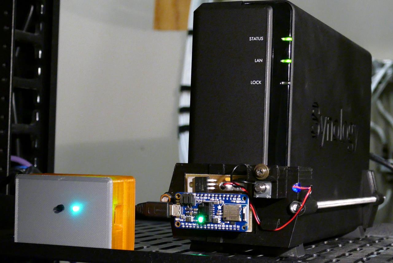
I 3D printed the brackets using black PLA filament to match the surveillance server color. The mini 5 V push pull solenoid fits snugly into the slot on the bracket, but just to make sure it doesn’t wiggle loose, I also printed a small cover plate to secure it. The plate is secured with a screw that self-taps into the hole above the solenoid. When activated the solenoid will only travel a few millimeters but it’s enough to engage the server’s power button.
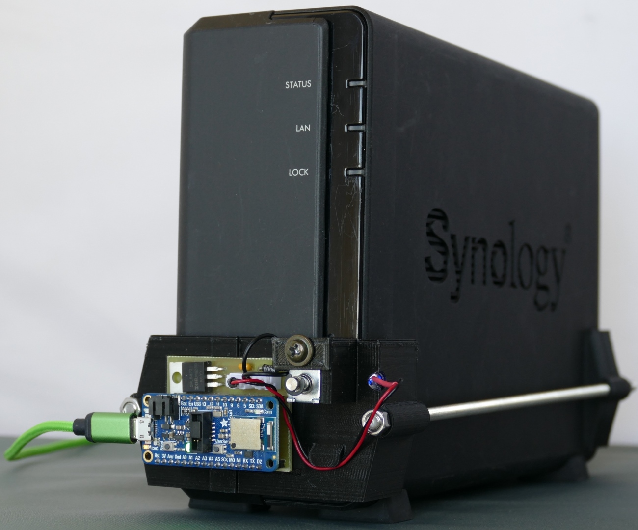
M5 x 250 mm fully threaded stainless steel rods connect the brackets. The assembly slides over the server and the nuts are tightened to hold it in place. The design affords easy adjustments to ensure the solenoid and LED are correctly positioned over the illuminated power button.
The A0 port on the Feather returns around 10,500 when the blue illuminated power button on the surveillance server is lit. The ADC is 16 bit resolution. The possible range is between 0 and 65,535. Therefore, the LED light detector is putting out about 528.7 mV
The server code requires the following libraries from the CircuitPython Bundle:
- adafruit_ble
- adafruit_bluefruit_connect
The adafruit_ble library is being actively developed. The latest version can be obtained from the Adafruit CircuitPython BLE repo. Copy the 2 libraries to the lib folder on the Feather. Here’s the server code for the BLE peripheral.
 UPDATE: There has been breaking changes to the CircuitPython BLE library since this tutorial was created. All the following code has been updated as of 9/3/2022 to be compatible with CircuitPython 8.0.
from time import sleep
from adafruit_ble import BLERadio
from adafruit_ble.advertising.standard import ProvideServicesAdvertisement
from adafruit_ble.services.nordic import UARTService
from adafruit_bluefruit_connect.packet import Packet
from adafruit_bluefruit_connect.button_packet import ButtonPacket
from adafruit_bluefruit_connect.color_packet import ColorPacket
from board import A0, D13
from analogio import AnalogIn
from digitalio import DigitalInOut, Direction

led = AnalogIn(A0)  # Initialize blue LED light detector

solenoid = DigitalInOut(D13)  # Initialize solenoid
solenoid.direction = Direction.OUTPUT
solenoid.value = False

ble = BLERadio()
uart_server = UARTService()
advertisement = ProvideServicesAdvertisement(uart_server)

while True:
    ble.start_advertising(advertisement)  # Advertise when not connected.
    while not ble.connected:
        pass

    while ble.connected:  # Connected
        if uart_server.in_waiting:  # Check BLE commands
            packet = Packet.from_stream(uart_server)
            if isinstance(packet, ButtonPacket):
                if packet.button == '1' and packet.pressed:
                    solenoid.value = True  # Activate solenoid for 1 second
                    sleep(1)
                    solenoid.value = False

        led_intensity = led.value  # Check blue LED detector intensity
        led_on = led_intensity > 1000
        # Color: red = off, green = on
        color_packet = ColorPacket((255 * int(not led_on), 255 * led_on, 0))
        try:
            uart_server.write(color_packet.to_bytes())  # Transmit state color
        except OSError:
            pass

        sleep(.2)
The code starts BLE advertising and then waits for a client connection. Afterwards, it continuously polls the BLE UART buffer for button packets. Upon receipt of the correct packet the solenoid is fired by setting the corresponding GPIO pin high for 1 second. The program also monitors the ADC pin connected to the LED light detector. If the 16 bit result is greater than 1000 (about 50 mV) then a green color packet is transmitted to the client. Otherwise, a red color packet is sent. I found the noise on the ADC line with the filter to be under 100 (about 5 mV). Therefore, the threshold is an order of magnitude greater than the noise and still an order of magnitude less than the typical 500 mV output of an illuminated LED.
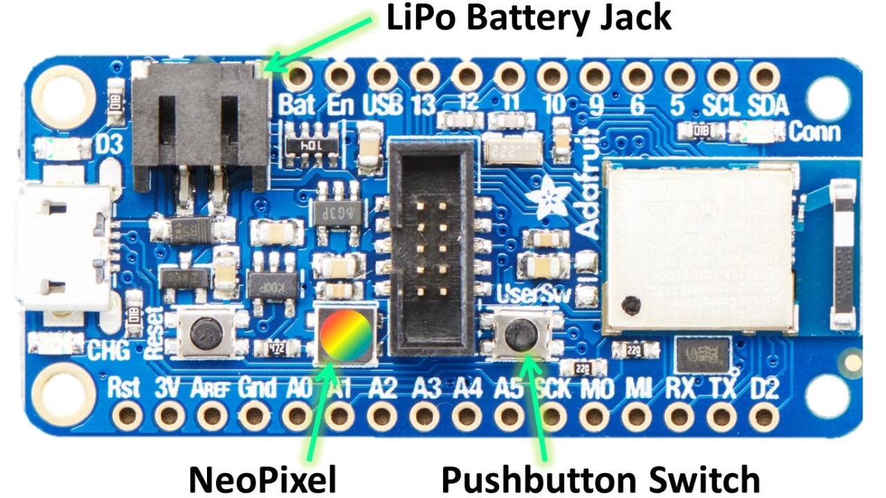
The remote control client will just be another Adafruit Feather nRF52840 Express board. The board comes with a built in NeoPixel and a push button switch so no external components will be required. It also has a LiPo battery jack and charging circuit so the remote control can be battery operated.
Adafruit provides free modular case designs on Thingiverse to house the Feather boards. The STL files are easy to modify and 3D print. Here are the 3D printed parts.
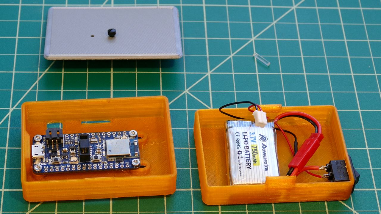
The bottom container holds the battery and an on/off switch. The default design has a mini slide switch. I modified it to a mini rocker because I prefer the more defined throw. When the switch is turned on the battery will power the Feather. The 2 modular containers snap securely together. I drilled 2 holes in the grey case lid. I inserted a black nylon screw through one hole and secured it with a nylon stand-off. It will actuate the built-in push button switch on the Feather. The other hole will hold a segment of 2mm end glow fiber optic filament. This will act as light tube for the built-in NeoPixel on the Feather.
The client code requires the following libraries from the CircuitPython Bundle:
- adafruit_ble
- adafruit_bluefruit_connect
- adafruit_debouncer
- adafruit_fancyled
- neopixel
Here’s the client code for the BLE remote control (updated 9/3/2022).
from adafruit_ble import BLERadio
from adafruit_ble.advertising.standard import ProvideServicesAdvertisement
from adafruit_ble.services.nordic import UARTService
from adafruit_bluefruit_connect.packet import Packet
from adafruit_bluefruit_connect.button_packet import ButtonPacket
from adafruit_bluefruit_connect.color_packet import ColorPacket
from neopixel import NeoPixel
from binascii import unhexlify
from board import NEOPIXEL, SWITCH
from adafruit_debouncer import Debouncer
from digitalio import DigitalInOut, Direction, Pull
from time import sleep
import adafruit_fancyled.adafruit_fancyled as fancy

pin = DigitalInOut(SWITCH)  # Set up built-in pushbutton switch
pin.direction = Direction.INPUT
pin.pull = Pull.UP
switch = Debouncer(pin)

pixels = NeoPixel(NEOPIXEL, 1)  # Set up built-in NeoPixel

AQUA = const(0x00FFFF)    # (0, 255, 255)
GREEN = const(0x00FF00)   # (0, 255, 0)
ORANGE = const(0xFF8000)  # (255, 128, 0)
RED = const(0xFF0000)     # (255, 0, 0)
BLUE = const(0x0000FF)    # (0, 0, 255)

gradients = {'Off': [(0.0, RED), (0.75, ORANGE)],
             'On':  [(0.0, GREEN), (1.0, AQUA)]}
palette = fancy.expand_gradient(gradients['Off'], 30)

gamma_levels = (0.25, 0.3, 0.15)
color_index = 1
fade_direction = 1

TARGET = 'f0:74:72:60:87:d2'  # CHANGE TO YOUR BLE ADDRESS
target_address = TARGET.split(":")  # Convert address string to list of bytes
target_address.reverse()  # Reverse bytes to match Address class little-endian
target_address = unhexlify(''.join(target_address))  # Convert list to bytes

button_packet = ButtonPacket("1", True)  # Transmits pressed button 1

ble = BLERadio()
uart_client = None

while True:
    uart_addresses = []
    pixels[0] = BLUE  # Blue LED indicates disconnected status
    pixels.show()

    if not uart_client:
        print("Trying to connect to BLE server...")
        # Keep trying to find target UART peripheral
        for adv in ble.start_scan(ProvideServicesAdvertisement):
            print(adv.address.address_bytes)  # Print detected addresses
            if adv.address.address_bytes == target_address:
                uart_client = ble.connect(adv)
                print("Connected")
                break
        ble.stop_scan()

    if uart_client and uart_client.connected:
        uart_service = uart_client[UARTService]
        while uart_client and uart_client.connected:  # Connected
            switch.update()
            if switch.fell:  # Check for button press
                try:
                    # Transmit press
                    uart_service.write(button_packet.to_bytes())
                except OSError:
                    pass
            # Check for LED status receipt
            if uart_service.in_waiting:
                packet = Packet.from_stream(uart_service)
                if isinstance(packet, ColorPacket):
                    # Color match
                    if fancy.CRGB(*packet.color).pack() == GREEN:
                        # Green indicates on state
                        palette = fancy.expand_gradient(gradients['On'], 30)
                    else:
                        # Otherwise red indicates off
                        palette = fancy.expand_gradient(gradients['Off'], 30)

            # NeoPixel color fading routing
            color = fancy.palette_lookup(palette, color_index / 29)
            color = fancy.gamma_adjust(color, brightness=gamma_levels)
            c = color.pack()
            pixels[0] = c
            pixels.show()
            if color_index == 0 or color_index == 28:
                fade_direction *= -1  # Change direction
            color_index += fade_direction

            sleep(0.02)
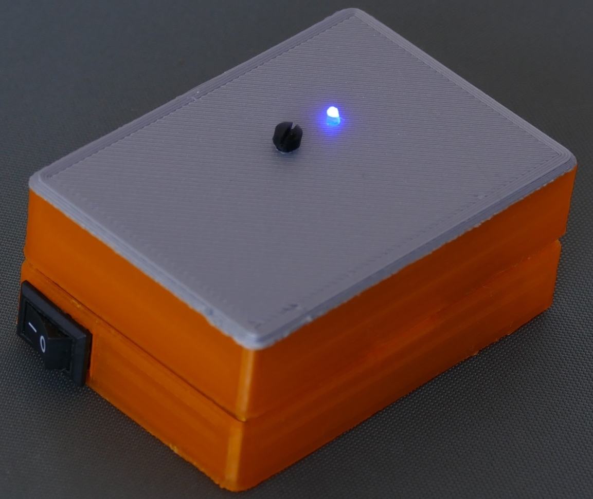
The program scans for BLE peripherals and connects once the target is located. The user switch is debounced. Generally speaking, when a mechanical switch is pressed it doesn’t just change from open to closed. The metal contacts oscillate for a few milliseconds. This can trick a microcontroller into reading multiple presses. The debouncer suppresses these erroneous readings. When the switch is pressed a button packet is sent to the server to activate the solenoid. Next the code monitors the UART buffer for color packets and uses FancyLED to generate smooth LED color fading for the corresponding color palette. The remote control fades green/aqua if the server is on. Otherwise, it fades red/orange.
The remote control works great outside the closet and has excellent range even with the closet door closed.
Downloads:
CircuitPython Client & Server Code (09/03/2022) LATEST VERSION
CircuitPython Client & Server Code (09/24/2019) DEPRECATED
Eagle Schematics & PCB Board
SketchUp Case & Bracket Files
 Note: Adafruit reached out to me and told me they liked my tutorial. They offered to pay me a small fee to publish it on their website.
2 Trackbacks