
This tutorial demonstrates repairing a PC that was bricked by a failed BIOS upgrade. An open source utility called FlashRom running on a Raspberry Pi is used to program the new firmware directly onto the motherboard’s serial flash chip.
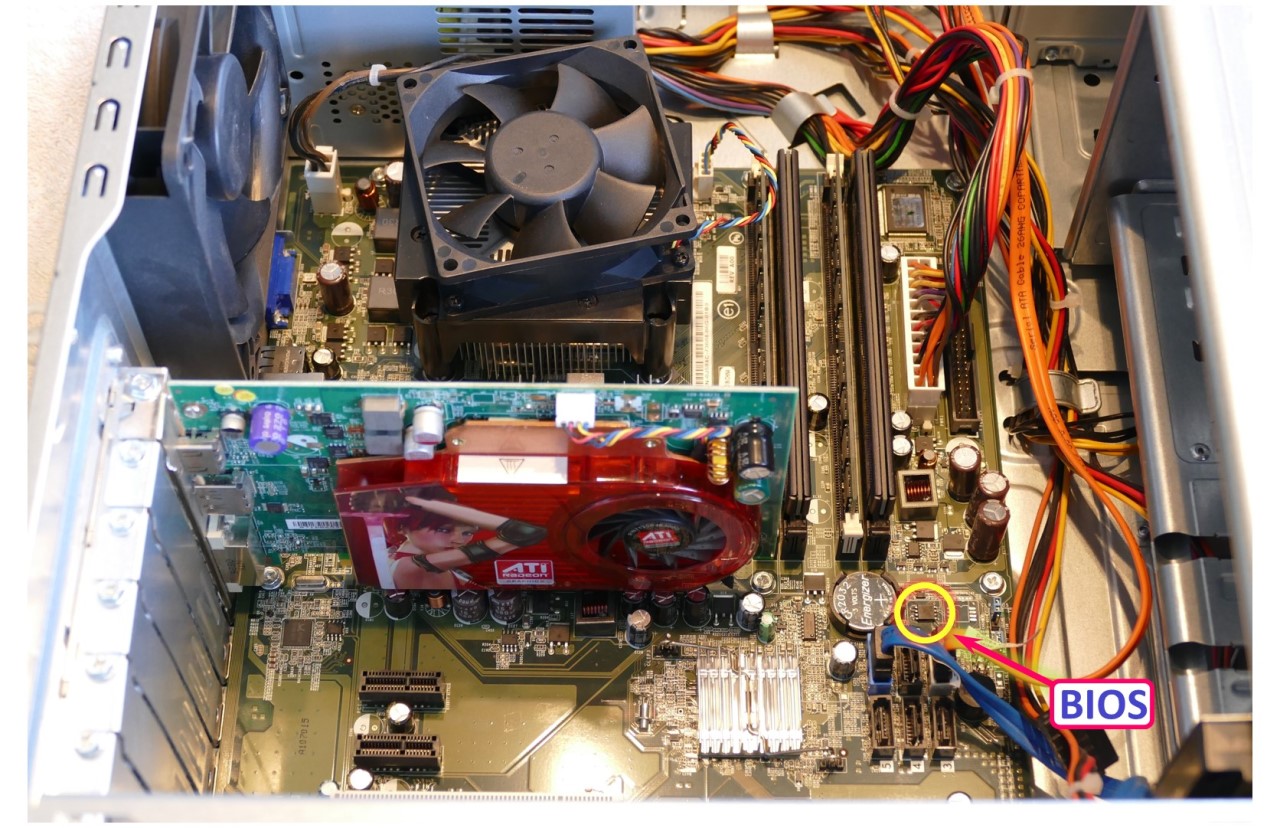
I wanted to upgrade the RAM on a Dell Vostro 410. The upgrade was only supported by the latest firmware. So I downloaded the BIOS update utility from Dell’s support page. I closed all open apps, disabled the AV software and ran the update. It promptly crashed and bricked the computer. Nothing but a black screen on boot with fans running full blast. Below is the Dell Vostro 410 motherboard circa 2008. The location of the BIOS chip is circled. They are often located near the CMOS battery. By the way, the techniques used in this tutorial are applicable to other motherboards and are not limited to Dell or even to computers. Routers, TV’s, oscilloscopes, washing machines, any electronic device that supports upgrades can have re-programmable firmware.
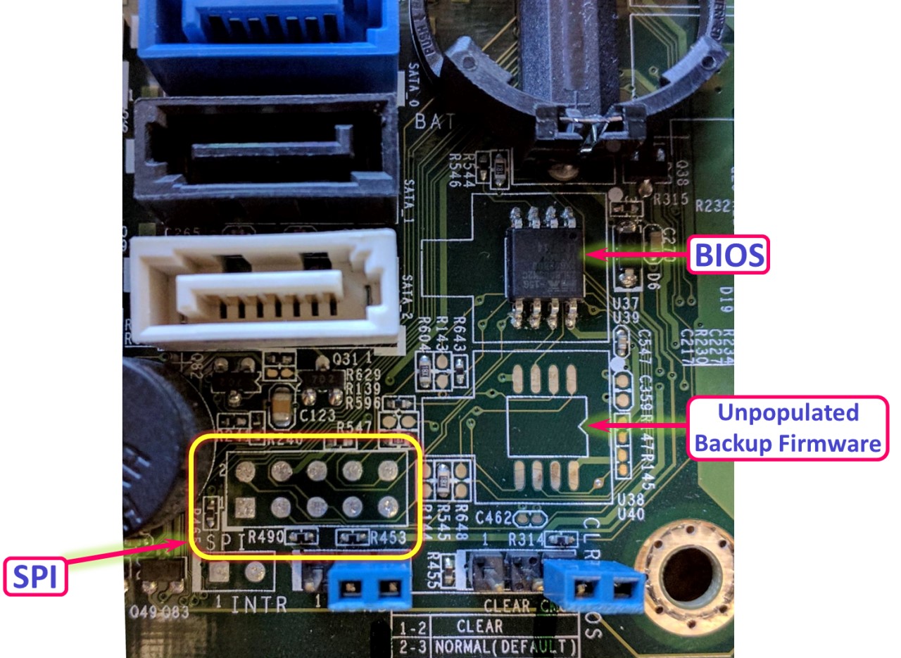
Below is a close up of the BIOS EEPROM chip that stores the firmware. EEPROM stands for Electrically Erasable Programmable Read-Only Memory. EEPROM’s have non-volatile memory which means their data is preserved even when the power is turned off. They’re referred to as read only but it is possible to write to them using an EEPROM programmer. For the record, the one below is a flash memory chip which is a type of EEPROM, or it might be more accurate to say flash was developed from EEPROM. I believe the unpopulated SOP pads underneath the flash chip is where a recovery firmware chip would go. Looks like Dell didn’t opt for this feature. However, to the left is an unpopulated 10 pin header labelled SPI which stands for serial peripheral interface.
SPI is a very common communication protocol that I have featured in several of my past tutorials such as:
Raspberry Pi AVR Programmer & SPI Tutorial
Raspberry Pi Graphics LCD Display Tutorial
Raspberry Pi Analog Water Sensor Tutorial
Raspberry Pi ESP32 MicroPython OLED Tutorial
The BIOS chip is a Macronix MX25L8005. It’s an 8 megabit CMOS SERIAL FLASH chip. It supports reading and writing via SPI protocol. Since the Raspberry Pi has a SPI port and the motherboard has a SPI port, in theory, it should be relatively easy to reprogram the corrupt chip. If your motherboard doesn’t have a SPI port, it may still be possible to program the chip by using IC Test Clips to connect the Pi directly to the chip.

I soldered a 10 position dual row male 2.54mm pin header to the unpopulated SPI port.
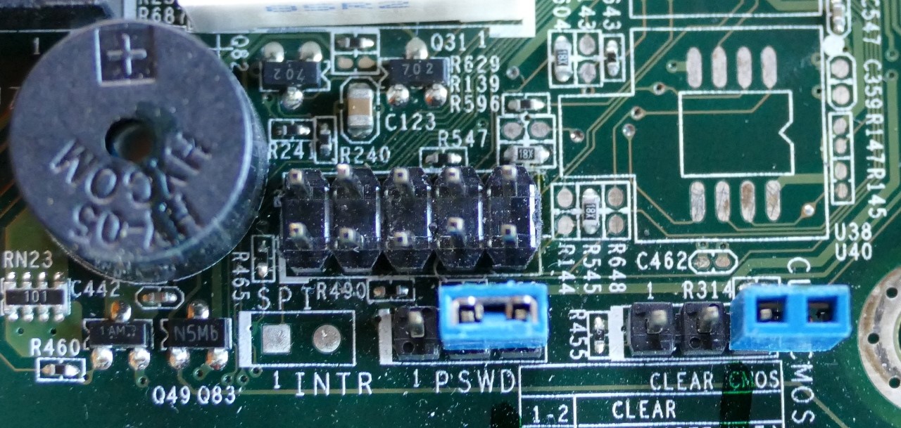
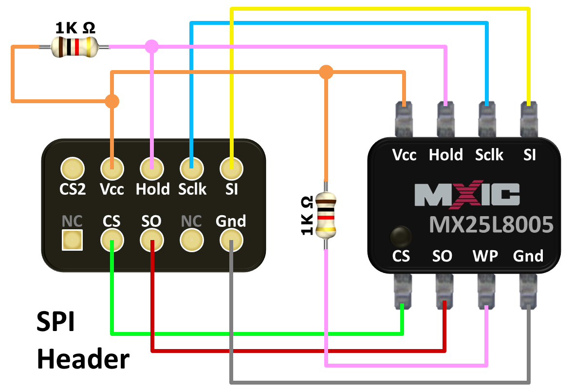
A multimeter continuity test can be used to tone out the SPI header. The pinout on the Vostro motherboard adheres to a standard called the SPI Universal Pin Header. The necessary SPI pins: chips select (CS), serial clock (Sclk), slave in (SI), slave out (SO), Vcc and ground are all connected from the chip to the header. Additionally, the hold and write protect pins are already pulled up with 1k Ω resistors to Vcc which is required for programming.
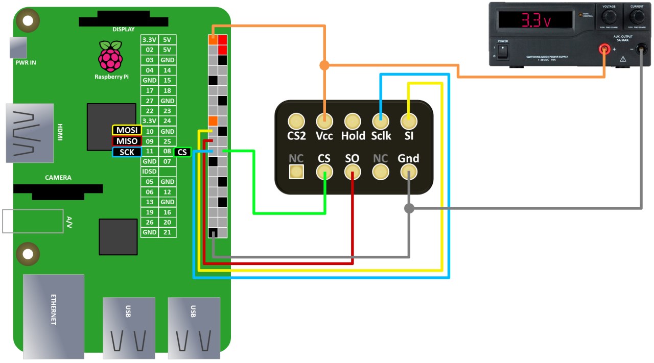
The Raspberry Pi SPI bus is comprised of chip select (CS) on GPIO 8, Master In Slave Out (MISO) on GPIO 9, Master Out Slave In (MOSI) on GPIO 10 and serial clock on GPIO 11. A ground from the Pi is connected to the ground on the header. The CS pins are connected together. MOSI is connected to SI. MISO is connected to SO. The serial clock pins are connected. A 3.3 V pin on the Pi is connected to the header Vcc pin. I recommend you make all connections with the power off. An ESD mat and an anti-static wrist strap would also be prudent. CMOS IC’s are sensitive to static electricity especially when out of circuit.
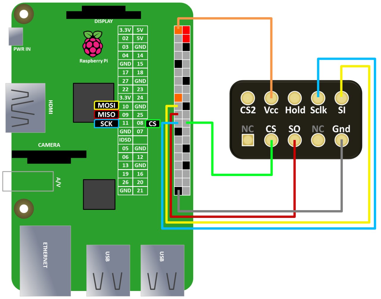
Depending on the current draw of the motherboard it might be necessary to use an external power supply to provide 3.3 V, especially on older first generation Pi’s because their 3.3 V rails can’t source much current. I’m not sure if it is necessary but it’s recommended to remove the motherboard CMOS battery and CMOS clear jumper prior to programming. I also recommend you keep the wires under 30 cm (12 inches) because shorter wires are more reliable.
 WARNING: Some flash chips operate at 1.8 V and can be damaged if connected directly to the Pi. In this case, you could theoretically use a BSS138 based logic level shifter and lower the SPI speed to around 1 MHz. Adafruit sells an inexpensive shifter.
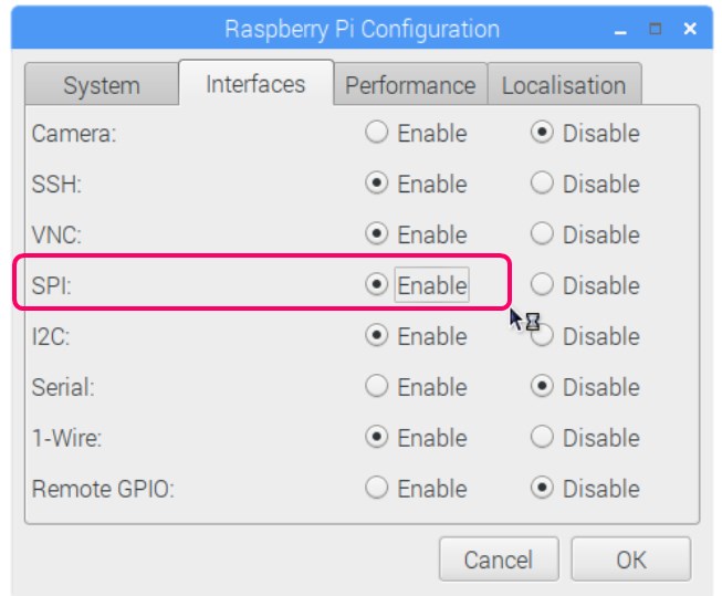
The Pi’s SPI interface is usually disabled by default. From the Pi’s main menu, click Preferences, click Raspberry Pi Configuration. Select the Interfaces tab. Click SPI enable. Then click OK to save the changes.
 FlashRom is a utility for identifying, reading, writing, verifying and erasing flash chips. Currently the supported hardware includes over 500 chips. I recommend you use a Raspberry Pi with the latest updated version of Raspbian. FlashRom is easy to install using sudo apt-get install flashrom.
sudo apt-get install flashrom
Tack p species the programmer which for the Pi is linux_spi. The device is spidev0.0 and 2000 KHz seems to be a reliable speed. The following command will identify the chip and test to ensure everything is working (Tack V enables verbose output).
flashrom -p linux_spi:dev=/dev/spidev0.0,spispeed=2000 -V
Unfortunately, the identification command failed on the Vostro 410 motherboard with No EEPROM/flash device found!
![]()
I made several attempts to remedy the failure. I tried swapping MISO and MOSI. I bypassed the header and clipped directly onto the chip. I played around with the SPI speed. I hooked up a bench power supply to provide the 3.3 V and experimented with higher voltages. I also tried all the jumper configurations. Existing circuit loading is a common pitfall when trying to program a chip in circuit. Another IC or component on the motherboard is probably interfering with the logic levels. Despite the failure with this motherboard, the SPI headers on other motherboards often work quite well so I recommend you still try the SPI port first. The obvious solution if SPI fails is to remove the chip from the board. Unfortunately the chip is not socketed so it will be necessary to desolder it. Ideally you would use a hot air rework station. If you don’t have one ChipQuik is a great solution.
ChipQuik is a lower melting point solder designed to remove surface mount chips with a minimal amount of heat. After applying flux you melt ChipQuik across all the pins. Unlike regular solder the ChipQuik stays molten for several seconds so you can heat the pins on 1 side and they will stay molten while you heat the pins on the other side. Once all the pins are heated the chip can easily be removed with a pair of ESD tweezers or a vacuum pick up.

 WARNING: soldering can be dangerous and you could destroy your motherboard. Please exercise caution.
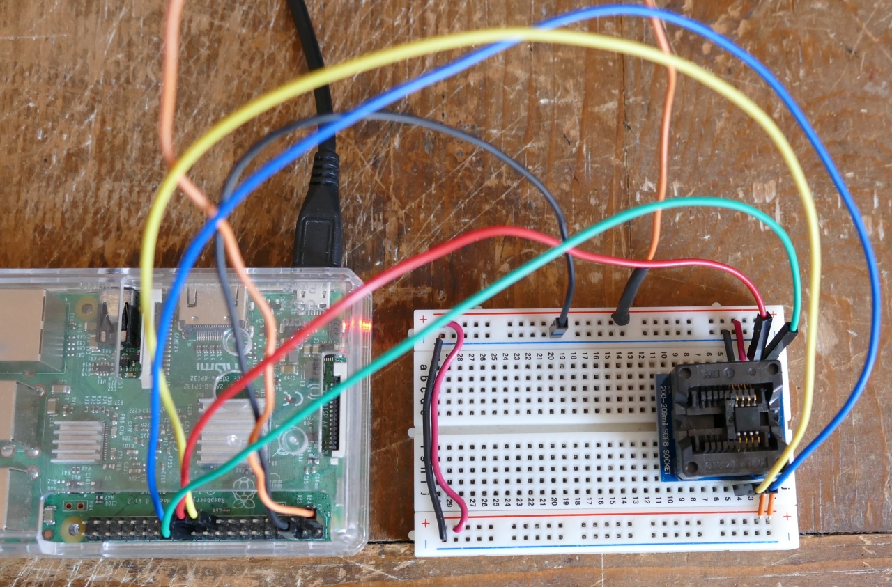
An 8 pin dip adapter for 200 mil SOP chips can be used to facilitate the hook up. It is breadboard compatible with room for 1 row on each side.

Press down on the adapter to open the jaws. Carefully drop the chip in. Pay attention to the orientation. The chip’s pin 1 is designated by a small circle recessed into the top of the chip. Releasing the jaws clamps the chip in place. Wiring the flash chip directly to the Pi is very similar to the SPI header hook up. VCC goes to 3.3 V, the grounds are connected, the clocks are connected, the chip selects are connected, MOSI goes to SI and MISO goes to SO. It’s also necessary to connect Hold and Write Protect to 3.3 V. Again I recommend making all connections with the power off.

On a breadboard, the SOP adapter contains the BIOS chip and is wired to the Raspberry Pi.
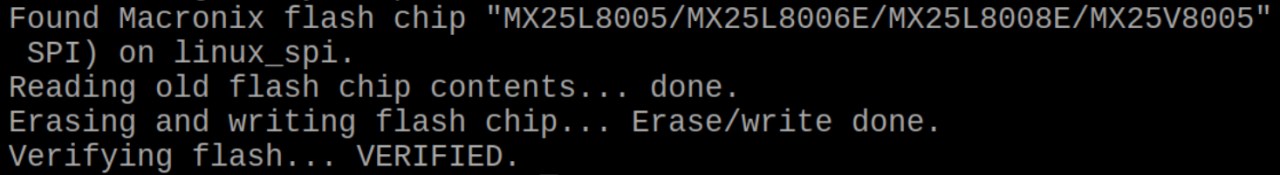
Run the FlashRom command again and this time you should receive a message indicating the chip was found such as “Found Macronix flash chip…” After a successful identification I recommend you read the corrupt firmware to disk using FlashRom tack r.
flashrom -p linux_spi:dev=/dev/spidev0.0,spispeed=2000 -r bricked.bin
Even though this firmware is corrupt it’s a good idea to save it because if something goes wrong when writing it could be helpful to compare the old with the new. Also some motherboard vendors embed ID’s in free space on the chip that could be required for certain applications.
Next download the latest BIOS firmware from you manufacturer’s website. I downloaded the Vostro 410 BIOS from the Dell support site. Unfortunately, it’s wrapped up in a Windows executable. I tried uncompression software but it couldn’t unpack the binaries. Therefore a working Windows PC is required. The following primarily applies to Dell firmware. It might apply to other brands too. Open PowerShell and browse to the temp directory.
cd $env:temp
Use the ls command to list the directory contents. Now would be a good time to clean out your temp folder to make it easier to manage. Switch back to the desktop and run the executable. Stop at this point and do not proceed. The program will either throw an error because the BIOS isn’t compatible with your computer or it will prompt you to proceed. Either way do not proceed or close the message prompt. Instead switch back to PowerShell. Running ls again should show a new temporary folder. Next, cd into the new folder. List the contents using ls and look for binary file. It should have a bin extension. For the Vostro 410 firmware the file is named 7B1D1P19.bin. Copy the firmware to the desktop.
cp 7b1d1P19.bin $env:userprofile\desktop
You need to copy it out because this temporary folder will be deleted as soon as you close the prior message prompt. After the copy completes, the prompt can be closed and BIOS utility can be cancelled. Next transfer the binary file to the Pi using FTP or a USB flash drive.
Flashrom is run again. Append tack w for write and specify the binary filename .
flashrom -p linux_spi:dev=/dev/spidev0.0,spispeed=2000 -w 7B1D1p19.BIN
If all goes correctly you should receive the message indicating a VERIFIED flash.
Remove the chip from the adapter and solder it back onto the motherboard. A hoof tip works will for soldering surface mount parts. Please make sure you use regular solder (not ChipQuik) and always use flux. Then replace the CMOS battery and restore the CMOS clear jumper. Turn your computer on and if all goes well, you will hear a beep followed by the BIOS POST (power on self test) screen.