
This MicroPython tutorial will demonstrate how to connect and drive a color SSD1351 OLED display using an ESP32. It will also touch on using the ADC pins to read analog signals and FTP for file transfers.
This is the 4th video in my MicroPython ESP32 series.
- Part 1 demonstrates loading the ESP32 firmware, file manipulation with Rshell and NeoPixel LED’s.
- Part 2 uses MQTT to wirelessly transmit data from temperature/humidity sensors.
- Part 3 sets up a web server on the ESP32 that provides lighting control and sensor feedback.
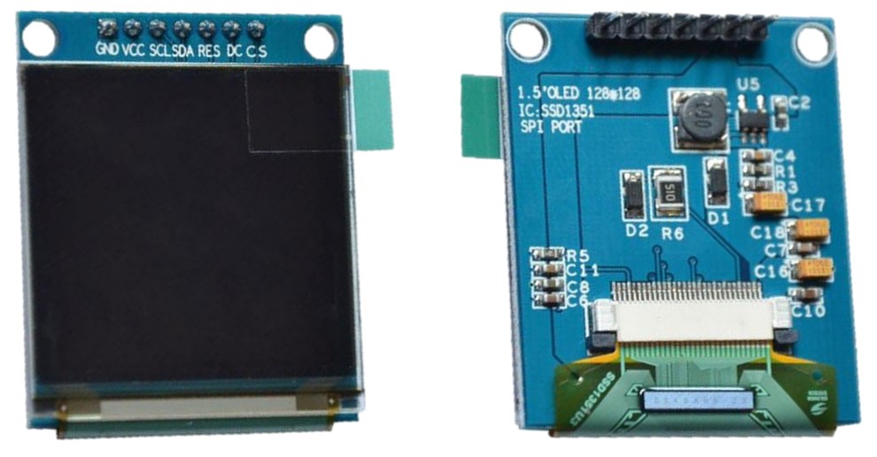
The SSD1351 color 1.5″ 128×128 OLED breakout module is a very high quality display. I recommend you get the display with the integrated breakout board because it is much easier to interface.
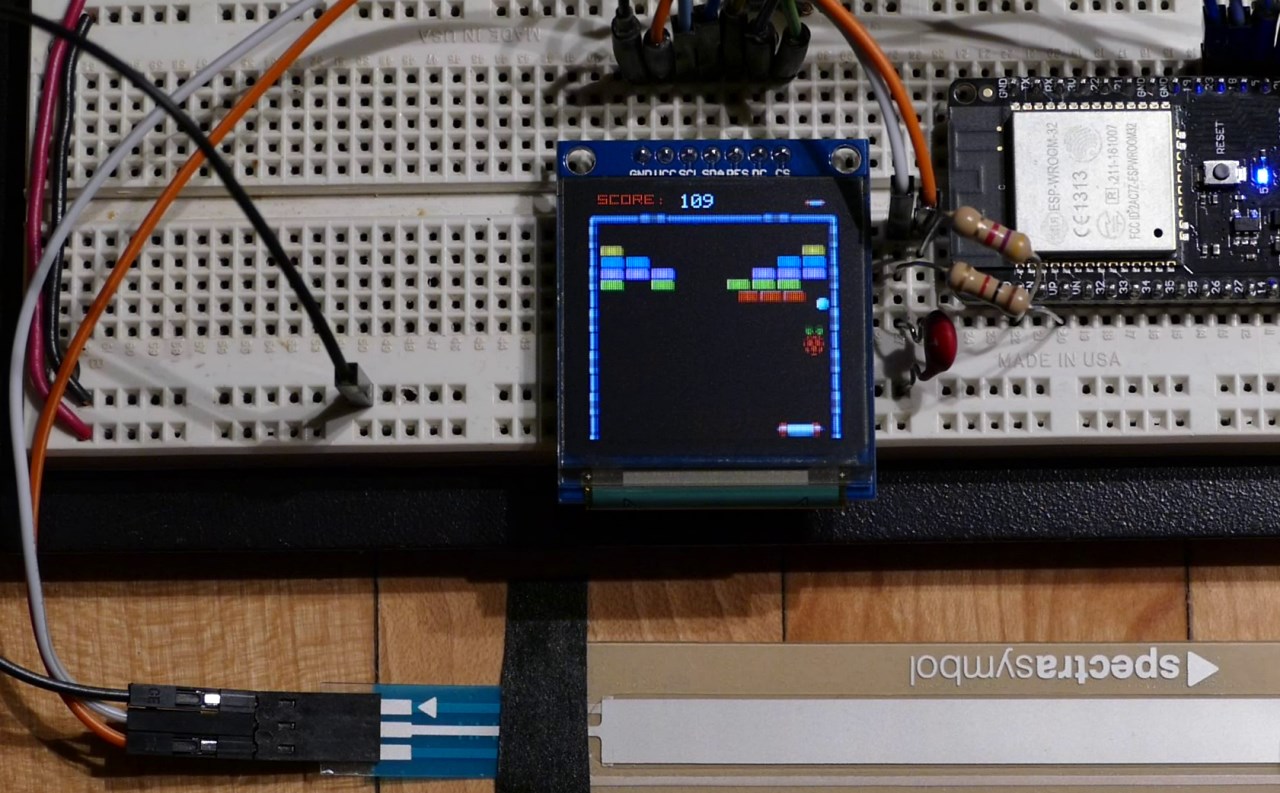
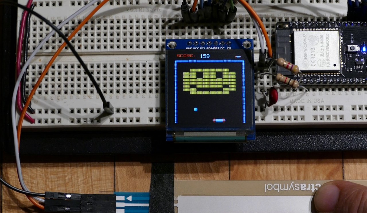
I wrote a simple brick game similar to the arcade classic Arkanoid and I’m using a touch sensitive linear potentiometer connected to an ADC pin to control the paddle. I wrote the game and the display drivers completely in MicroPython. The SSD1351 drivers, demos and game code can be downloaded from my GitHub repo.
OLED displays have many advantages:
- True blacks and better contrast (Each pixel produces its own light as opposed to being back or edge lit.)
- Very sharp and vibrant colors (OLED displays are used in iPhone X, Galaxy S8 and Apple watch.)
- Thin and light weight.
- Excellent viewing angle.
- Hardware acceleration.
- Operates to -40C.
- Prices have been dropping.
- Lower power consumption (Although current draw is proportional to the lit pixel count so YMMV. At the default contrast of 10, the brick game averages about 45mA with a range between 28 to 72mA. Displaying the demo MicroPython128x128.raw image draws about 47mA. However, the demo image Tabby128x128.raw which is very bright draws over 190mA.)
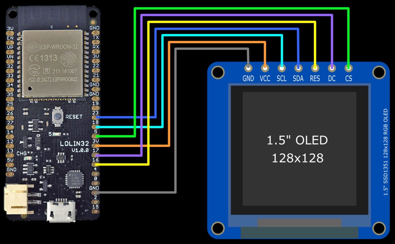
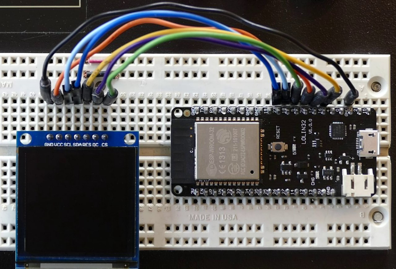
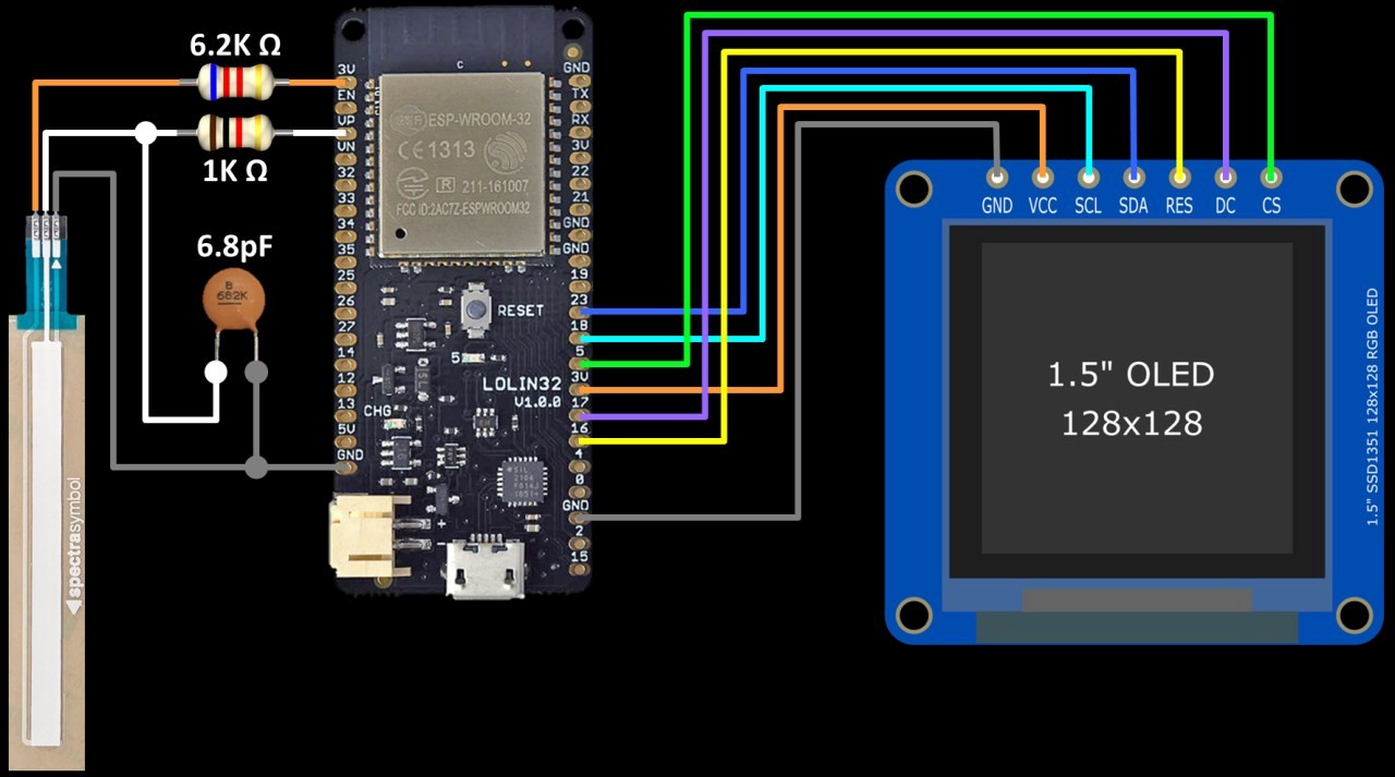
The SSD1351 module uses a SPI interface which I recommend over I2C because it’s faster. The board requires 5 GPIO pins to communicate with the ESP32 in addition to VCC and ground. The SSD1351 ground pin is connected to a ground on the ESP32. The VCC pin is connected to a 3.3V pin. The SCL pin is connected to GPIO18 which is the clock pin for the hardware VSPI bus. SDA is connected GPIO23 which is the MOSI pin for the same VSPI bus. RES (reset) is connected to GPIO16. DC (data/command) is connected to GPIO 17. CS (chip select) goes to GPIO5.
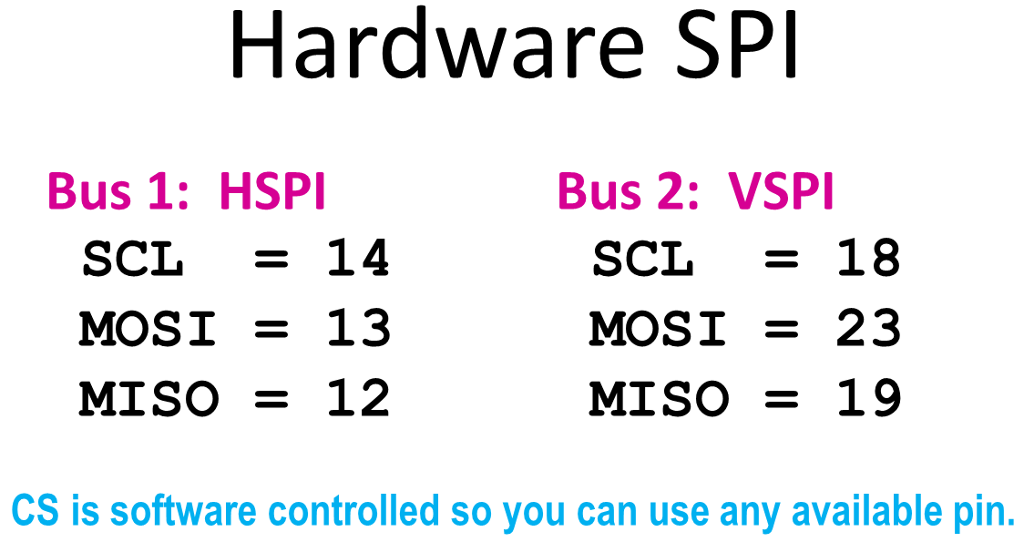
There are currently 2 available hardware SPI hosts on the ESP32, HSPI and VSPI. VSPI use pin 18 for clock, pin 23 for MOSI (master output slave input) and pin 19 for MISO (Master input slave output). Since this display is write only MISO is not needed. HSPI uses 14, 13 and 12 for clock, MOSI and MISO respectively. There are 2 other SPI buses but they are currently reserved for the core system. Also, VSPI can be reserved if you are using psRAM. The above may change in the future. The CS pins are controlled by software in MicroPython. Therefore, you don’t get any benefit from using the designated CS hardware pins. You don’t have to use the hardware pins for clock, MOSI and MISO. However, if you use alternative pins I believe this limits your baud rate to 20MHz.
Here’s the SSD1351 on a breadboard hooked up to a Wemos Lolin32.
I’m using a Raspberry Pi running the latest version of Raspbian to communicate with the Lolin32 which has the latest firmware build of MicroPython installed. Please see Part 1 in this series to learn how to load the ESP32 firmware and install Rshell.
Use git clone to download my MicroPython SSD1351 library. SSD1351.py is the main OLED library. I’ve included several examples that demonstrate how to use the library. The game above is also included along with several fonts, images, game levels and utilities.
git clone https://github.com/rdagger/micropython-ssd1351.git
A couple of viewers complained about Rshell’s slow transfer speed. Therefore, I’ll demonstrate a much quicker solution for managing files on the ESP32 using FTP. Robert-HH created a very handy light-weight FTP library that is compatible with the ESP32. You can download it using git clone.
git clone https://github.com/robert-hh/ESP8266-FTP-Server
The ftp.py file can be copied to the ESP32 using Rshell (on Windows and Mac you can use Adafruit’s Ampy utility.)
rshell --buffer-size=30 -p /dev/ttyUSB0 -a
cd ESP8266-FTP-Server
cp ftp.py /pyboard
To start the ftp server, use can use Rshell to enter the REPL and import it (on Windows you can use PuTTY and on a Mac you can use the built-in screen program.)
repl
import ftp
Once the FTP server is running you can use any FTP client to transfer and manage files on the ESP32. A basic FTP client can be installed on the Raspberry Pi.
sudo apt-get install ftp
To copy all the python files from the SSD1351 library to the ESP32 you can use mput. The prompt command disables input prompts.
ftp <The IP address of your ESP32>
prompt
mput *.py
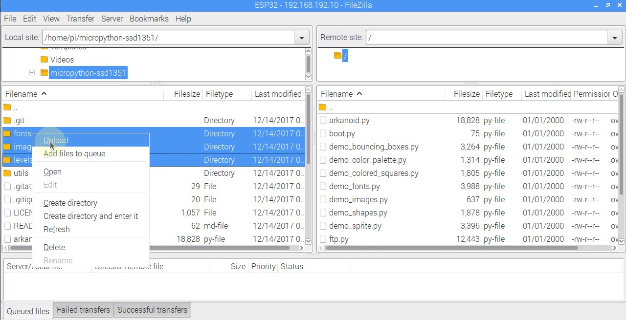
You can use ls to list files on the ESP32. !ls lists files on your local directory. You can change remote directors with cd and local directories with lcd. I find it tedious to copy sub-folders with the basic FTP client. I prefer FileZilla which is a free cross platform FTP client with a very user-friendly GUI. When you add your ESP32 to the FileZilla site manager please make sure you select passive transfer mode and check the box to limit the number of connections to one. Once connected just ctrl-click the 3 folders (fonts, images and levels) in the local directory on the Pi and right-click to upload them to the remote directory on the ESP32. Now the software will be ready to use.
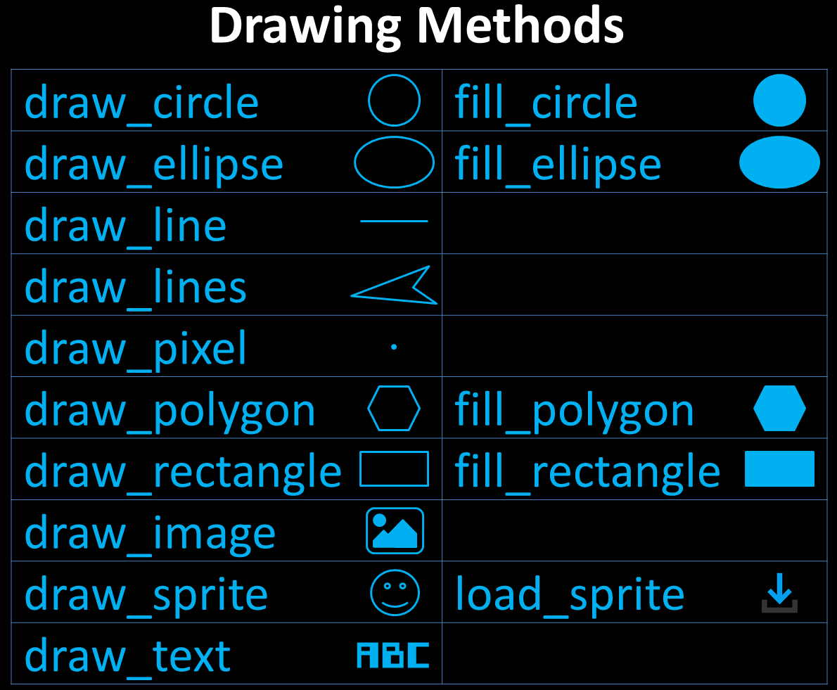
I’ve documented my SSD1351 OLED library thoroughly in addition to providing several demos. The library has support for most common geometric primitives such as circles, ellipses, lines, points, polygons and rectangles. Draw is for an outlined shape and fill is for a solid object.
Here’s an example of how to draw a radius 50 filled heptagon at coordinates 63, 63.
from time import sleep
from ssd1351 import Display, color565
from machine import Pin, SPI

spi = SPI(2, baudrate=14500000, sck=Pin(18), mosi=Pin(23))
display = Display(spi, dc=Pin(17), cs=Pin(5), rst=Pin(16))
display.fill_polygon(7, 63, 63, 50, color565(0, 255, 0))

sleep(5)
display.cleanup()
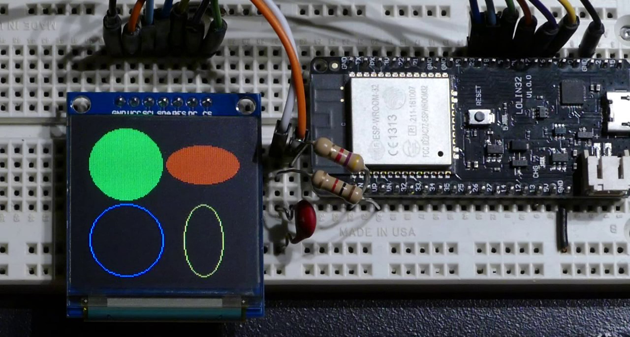
The demo files provide examples of most of library’s functionality. From the REPL run the first demo by typing import demo_shapes.
import demo_shapes
The screen should display several drawing examples.
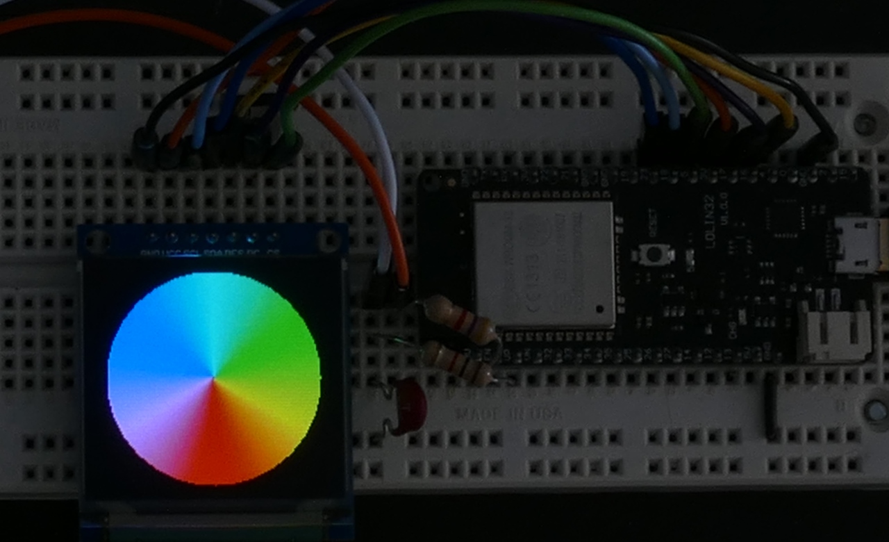
My library supports up to 65,535 different colors which is referred to as RGB565 color space. There are several demos regarding the color space (demo_color_palette.py, demo_color_wheel.py and demo_colored_squares.py.)
There are demos for animating sprites and loading images.
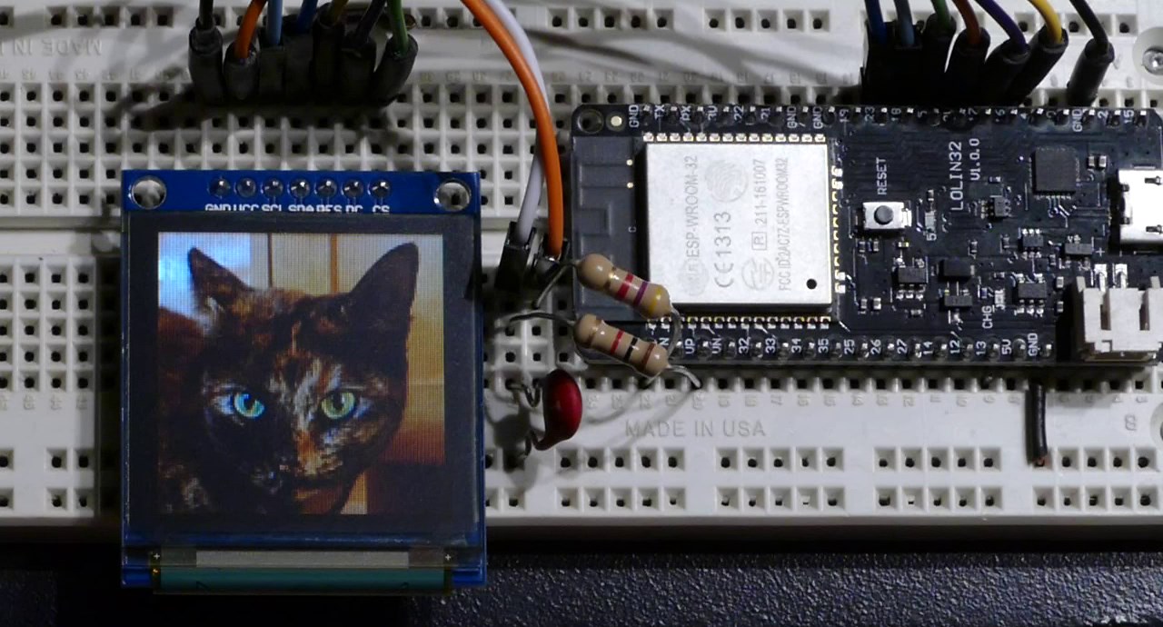
Sprites and images must be in RGB565 raw format. In my repo’s utils folder there is a command line python utility called img2rgb565.py which can convert standard images such as JPEG and PNG to the RGB565 raw format. The image dimensions must be less or equal to the display’s dimensions. Sprites are currently limited to 4096 bytes (Each pixel uses 2 bytes.) The img2rgb565 utility is Python only (not MicroPython.) It requires the Pillow library which can be installed using pip.
pip3 install Pillow
My SSD1351 library also has a module called xglcd_font that allows drawing colored text to the screen in portrait and landscape mode. Several fonts are included with my library.
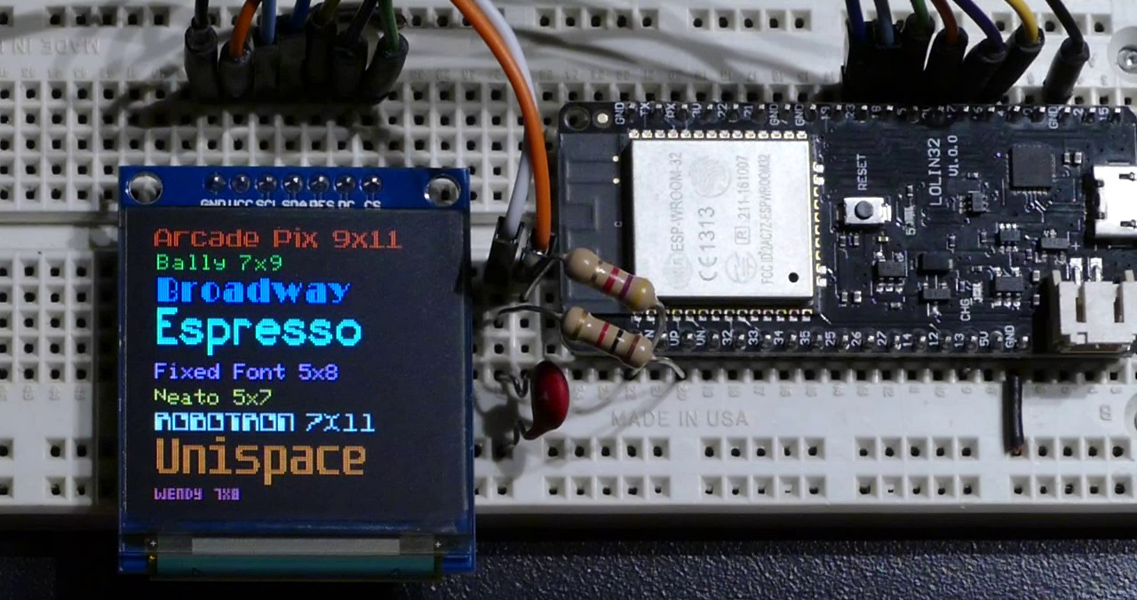
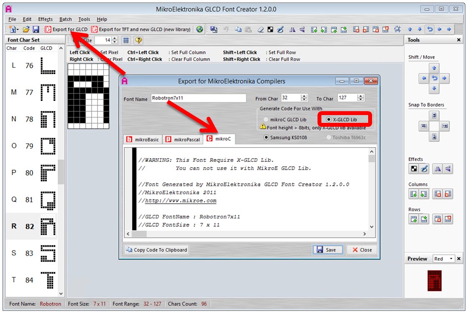
You can convert most TrueType fonts to X-GLCD format using the free edition of MikroElektronika GLCD Font Creator. Click Import an Existing System Font to load any TrueType font on your system.
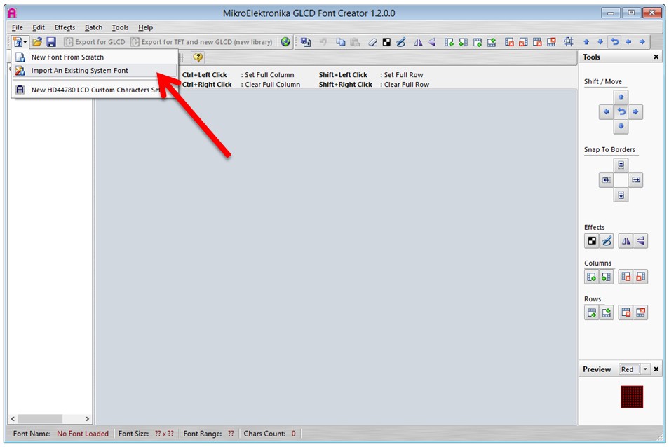
The default options should be OK. You might want to change the font size. Once loaded there is a rich set of features to edit the font characters. Click Export to GLCD to start the conversion. Make sure you select the mikroC tab and X-GLCD lib format. Then click save. I like to include the font pixel width and height in the name because you’ll need it later to load the font.
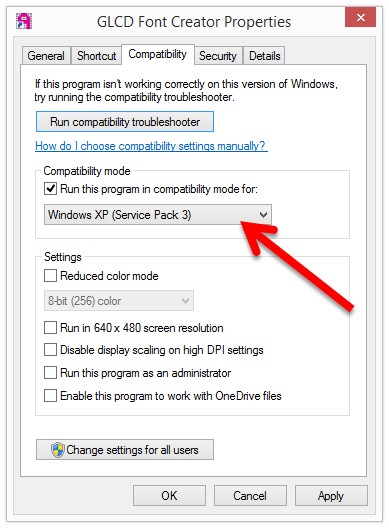
Unfortunately, this program is Windows only. Also if you are using a version higher than XP, you’ll need to run GLCD Font Creator in XP compatibility mode or else the save button will not work. Right click on the program shortcut and click properties. Select the compatibility tab and choose Run this program in compatibility mode for: Windows XP (Service Pack 3):
The following code draws text. The measure_text method is used to set X for centered text.
from time import sleep
from ssd1351 import Display, color565
from machine import Pin, SPI
from xglcd_font import XglcdFont

spi = SPI(2, baudrate=14500000, sck=Pin(18), mosi=Pin(23))
display = Display(spi, dc=Pin(17), cs=Pin(5), rst=Pin(16))

bally = XglcdFont('fonts/Bally7x9.c', 7, 9)
x = 63 - (bally.measure_text('Bally 7x9') // 2)  # Set x for centered text
display.draw_text(x, 12, 'Bally 7x9', bally, color565(0, 255, 0))

sleep(5)
display.cleanup()
For the brick game, I’m using a Spectra Symbol linear 10KΩ SoftPot. It functions similarly to a standard potentiometer. Pressing down along the pad changes the resistance. If you don’t have a SoftPot you can substitute a regular potentiometer. It could be hooked up exactly the same. One of the pot’s terminals is connected to ground. The other is connected to 3.3 volts in series with a 6200Ω resistor. By the default the ESP32 ADC pins can only read up to around 1 volt. I use the ADC atten method to set the attenuation to 6db which increases the range to 2.2 volts.
| Attenuation | Voltage Range |
|---|---|
| 0 dB | 0 - 1.1 V |
| 2.5 dB | 0 - 1.5 V |
| 6 dB | 0 - 2.2 V |
| 11 dB | 0 - 3.9 V |
A potentiometer is a variable voltage divider when the terminal ends are connected to a power supply. Moving the wiper varies the voltage on the middle pin. Without the resistor on the 3.3V terminal this would be zero to 3.3 volts. Since the ADC can only read about 2 volts, this would lose over a third of the pot’s range. The 6200Ω resistor offsets the pots range from zero to about 2 volts. This takes advantage of the pot’s range. For the video I used a 4700Ω resistor because it was the closest I could find in my parts bin. This puts the range around 0 – 2.25 volts which only sacrifices a little bit of range. The wiper is connected to GPIO 36 which is labelled VP. An optional resistor is placed in series. A 6.8 pF cap is placed between the wiper and ground to help smooth out some of the noise.
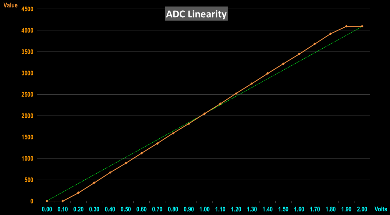
The ESP32 ADC is not very good. It’s very noisy and there are issues with linearity. I plotted the ADC values at 6db attenuation between 0 and 2 volts. The green indicates the ideal line. The orange is the actual values. There’s significant distortion towards both ends. However, most of the path is relatively straight. It’s linear enough for a game paddle. There’s just a little roughness when the paddle is close to the walls. If you were trying to read a sensor, you could use a polynomial equation to smooth out the readings. You could also increase the VCC terminal resistor and add one to the ground terminal. This could crop the voltage to the linear portion of the chart. Another alternative would be to use an external ADC chips such as the ADS1115 or the MCP3002. I have a Raspberry Pi tutorial on using external ADC chips.
The following code illustrates how to instantiate an ADC, set the attenuation and read a potentiometer hooked up to pin 36. For the game paddle I scale the returned ADC value 0 -4095 to my allowable paddle X-axis range of 6 – 98.
"""Code to read ADC."""
from machine import ADC, Pin
# Initialize ADC on VP pin 36.
adc = ADC(Pin(36))
# Set attenuation 0-2V (Will use 6.2K ohm resistor to limit pot to 2V).
adc.atten(ADC.ATTN_6DB)
# Set paddle position to pot ADC and scale 6 - 98.
x = adc.read() // 44 + 5
I’ve created 9 levels for the brick game. The binary level files are comprised of 3 bytes (x, y and color) for each brick. I placed the code (generate_levels.py) I used to generate them in the repo’s utils folder in case anyone wants to create more levels.
Part 5 of this tutorial demonstrates the ESP32 capacitive touch sensors, a UART controlled MP3 module and pulse width modulation.